Hydrometers Operation and Maintenance Manual - Baseline Systems
Hydrometers Operation and Maintenance Manual - Baseline Systems
Hydrometers Operation and Maintenance Manual - Baseline Systems

You also want an ePaper? Increase the reach of your titles
YUMPU automatically turns print PDFs into web optimized ePapers that Google loves.
<strong>Maintenance</strong> 6” Models, Cont.<br />
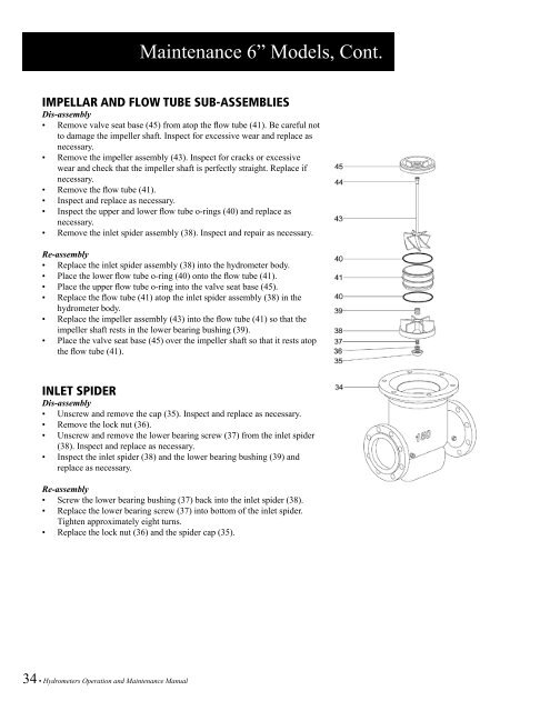
IMPELLAR AND FLOW TUBE SUB-ASSEMBLIES<br />
Dis-assembly<br />
• Remove valve seat base (45) from atop the flow tube (41). Be careful not<br />
to damage the impeller shaft. Inspect for excessive wear <strong>and</strong> replace as<br />
necessary.<br />
• Remove the impeller assembly (43). Inspect for cracks or excessive<br />
wear <strong>and</strong> check that the impeller shaft is perfectly straight. Replace if<br />
necessary.<br />
• Remove the flow tube (41).<br />
• Inspect <strong>and</strong> replace as necessary.<br />
• Inspect the upper <strong>and</strong> lower flow tube o-rings (40) <strong>and</strong> replace as<br />
necessary.<br />
• Remove the inlet spider assembly (38). Inspect <strong>and</strong> repair as necessary.<br />
Re-assembly<br />
• Replace the inlet spider assembly (38) into the hydrometer body.<br />
• Place the lower flow tube o-ring (40) onto the flow tube (41).<br />
• Place the upper flow tube o-ring into the valve seat base (45).<br />
• Replace the flow tube (41) atop the inlet spider assembly (38) in the<br />
hydrometer body.<br />
• Replace the impeller assembly (43) into the flow tube (41) so that the<br />
impeller shaft rests in the lower bearing bushing (39).<br />
• Place the valve seat base (45) over the impeller shaft so that it rests atop<br />
the flow tube (41).<br />
INLET SPIDER<br />
Dis-assembly<br />
• Unscrew <strong>and</strong> remove the cap (35). Inspect <strong>and</strong> replace as necessary.<br />
• Remove the lock nut (36).<br />
• Unscrew <strong>and</strong> remove the lower bearing screw (37) from the inlet spider<br />
(38). Inspect <strong>and</strong> replace as necessary.<br />
• Inspect the inlet spider (38) <strong>and</strong> the lower bearing bushing (39) <strong>and</strong><br />
replace as necessary.<br />
Re-assembly<br />
• Screw the lower bearing bushing (37) back into the inlet spider (38).<br />
• Replace the lower bearing screw (37) into bottom of the inlet spider.<br />
Tighten approximately eight turns.<br />
• Replace the lock nut (36) <strong>and</strong> the spider cap (35).<br />
34 • <strong>Hydrometers</strong> <strong>Operation</strong> <strong>and</strong> <strong>Maintenance</strong> <strong>Manual</strong>