Hydrometers Operation and Maintenance Manual - Baseline Systems
Hydrometers Operation and Maintenance Manual - Baseline Systems
Hydrometers Operation and Maintenance Manual - Baseline Systems

You also want an ePaper? Increase the reach of your titles
YUMPU automatically turns print PDFs into web optimized ePapers that Google loves.
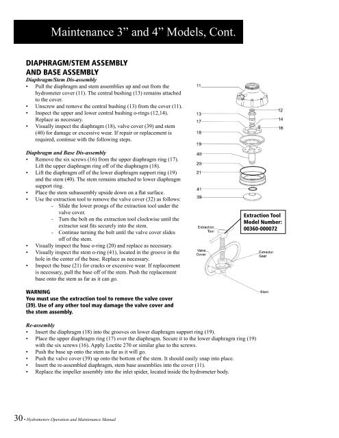
<strong>Maintenance</strong> 3” <strong>and</strong> 4” Models, Cont.<br />
DIAPHRAGM/STEM ASSEMBLY<br />
AND BASE ASSEMBLY<br />
Diaphragm/Stem Dis-assembly<br />
• Pull the diaphragm <strong>and</strong> stem assemblies up <strong>and</strong> out from the<br />
hydrometer cover (11). The central bushing (13) remains attached<br />
to the cover.<br />
• Unscrew <strong>and</strong> remove the central bushing (13) from the cover (11).<br />
• Inspect the upper <strong>and</strong> lower central bushing o-rings (12,14).<br />
Replace as necessary.<br />
• Visually inspect the diaphragm (18), valve cover (39) <strong>and</strong> stem<br />
(40) for damage or excessive wear. If repair or replacement is<br />
required, continue with the following steps.<br />
Diaphragm <strong>and</strong> Base Dis-assembly<br />
• Remove the six screws (16) from the upper diaphragm ring (17).<br />
Lift the upper diaphragm ring off of the diaphragm (18).<br />
• Lift the diaphragm off of the lower diaphragm support ring (19)<br />
<strong>and</strong> the stem (40). The stem remains attached to lower diaphragm<br />
support ring.<br />
• Place the stem subassembly upside down on a flat surface.<br />
• Use the extraction tool to remove the valve cover (32) as follows:<br />
- Slide the lower prongs of the extraction tool under the<br />
valve cover.<br />
- Turn the bolt on the extraction tool clockwise until the<br />
extractor seat fits securely into the stem.<br />
- Continue turning the bolt until the valve cover slides<br />
off of the stem.<br />
• Visually inspect the base o-ring (20) <strong>and</strong> replace as necessary.<br />
• Visually inspect the stem o-ring (41), located in the groove in the<br />
hole in the center of the base. Replace as necessary.<br />
• Inspect the base (21) for cracks or excessive wear. If replacement<br />
is necessary, pull the base off of the stem. Push the replacement<br />
base onto the stem as far as it can go.<br />
Extraction Tool<br />
Model Number:<br />
00360-000072<br />
WARNING<br />
You must use the extraction tool to remove the valve cover<br />
(39). Use of any other tool may damage the valve cover <strong>and</strong><br />
the stem assembly.<br />
Re-assembly<br />
• Insert the diaphragm (18) into the grooves on lower diaphragm support ring (19).<br />
• Place the upper diaphragm ring (17) over the diaphragm. Secure it to the lower diaphragm ring (19)<br />
with the six screws (16). Apply Loctite 270 or similar glue to the screws.<br />
• Push the base up onto the stem as far as it will go.<br />
• Push the valve cover (39) up onto the bottom of the stem. It should easily snap into place.<br />
• Insert the re-assembled diaphragm, stem base assemblies into the cover (11).<br />
• Replace the impeller assembly into the inlet spider, located inside the hydrometer body.<br />
30 • <strong>Hydrometers</strong> <strong>Operation</strong> <strong>and</strong> <strong>Maintenance</strong> <strong>Manual</strong>