Hydrometers Operation and Maintenance Manual - Baseline Systems
Hydrometers Operation and Maintenance Manual - Baseline Systems
Hydrometers Operation and Maintenance Manual - Baseline Systems

You also want an ePaper? Increase the reach of your titles
YUMPU automatically turns print PDFs into web optimized ePapers that Google loves.
<strong>Maintenance</strong> 1½” <strong>and</strong> 2” Models<br />
1½” <strong>and</strong> 2” <strong>Hydrometers</strong><br />
The dis-assembly of the hydrometer is divided into the following assemblies:<br />
• Cover Assembly<br />
• Diaphragm/Stem <strong>and</strong> Base Assemblies<br />
• Inlet Spider/Strainer Assembly<br />
Perform only those procedures necessary to inspect <strong>and</strong> replace parts as directed by the<br />
troubleshooting procedures. It is recommended to replace the various o-rings <strong>and</strong> gaskets<br />
during dis-assembly as well as to inspect certain other parts. All gaskets <strong>and</strong> o-rings must<br />
be covered with grease prior to installation.<br />
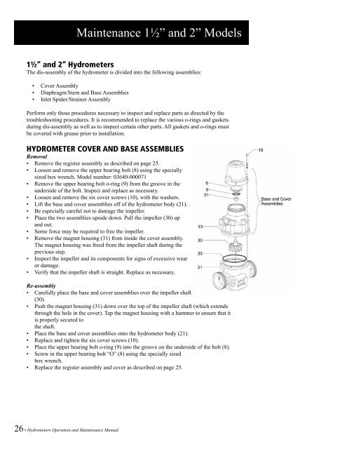
HYDROMETER COVER AND BASE ASSEMBLIES<br />
Removal<br />
• Remove the register assembly as described on page 25.<br />
• Loosen <strong>and</strong> remove the upper bearing bolt (8) using the specially<br />
sized box wrench. Model number: 03640-000071<br />
• Remove the upper bearing bolt o-ring (9) from the groove in the<br />
underside of the bolt. Inspect <strong>and</strong> replace as necessary.<br />
• Loosen <strong>and</strong> remove the six cover screws (10), with the washers.<br />
• Lift the base <strong>and</strong> cover assemblies off of the hydrometer body (21).<br />
• Be especially careful not to damage the impeller.<br />
• Place the two assemblies upside down. Pull the impeller (30) up<br />
<strong>and</strong> out.<br />
• Some force may be required to free the impeller.<br />
• Remove the magnet housing (31) from inside the cover assembly.<br />
The magnet housing was freed from the impeller shaft during the<br />
previous step.<br />
• Inspect the impeller <strong>and</strong> its components for signs of excessive wear<br />
or damage.<br />
• Verify that the impeller shaft is straight. Replace as necessary.<br />
Re-assembly<br />
• Carefully place the base <strong>and</strong> cover assemblies over the impeller shaft<br />
(30).<br />
• Push the magnet housing (31) down over the top of the impeller shaft (which extends<br />
through the hole in the cover). Tap the magnet housing with a hammer to ensure that it<br />
is properly secured to<br />
the shaft.<br />
• Place the base <strong>and</strong> cover assemblies onto the hydrometer body (21).<br />
• Replace <strong>and</strong> tighten the six cover screws (10).<br />
• Place the upper bearing bolt o-ring (9) into the groove on the underside of the bolt (8).<br />
• Screw in the upper bearing bolt “O” (8) using the specially sized<br />
box wrench.<br />
• Replace the register assembly <strong>and</strong> cover as described on page 25.<br />
26 • <strong>Hydrometers</strong> <strong>Operation</strong> <strong>and</strong> <strong>Maintenance</strong> <strong>Manual</strong>