Toilet Call System - Protec Fire Detection
Toilet Call System - Protec Fire Detection
Toilet Call System - Protec Fire Detection

You also want an ePaper? Increase the reach of your titles
YUMPU automatically turns print PDFs into web optimized ePapers that Google loves.
<strong>Protec</strong><br />
<strong>Protec</strong> <strong>Fire</strong> <strong>Detection</strong> plc<br />
• Easy to Install and Expand<br />
• Brushed Stainless Steel Kit (Optional)<br />
• Output to Interface with Local Refuge<br />
Outstation<br />
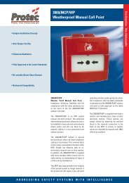
<strong>Protec</strong> <strong>Toilet</strong> <strong>Call</strong> <strong>System</strong><br />
Pull Cord Unit<br />
Overdoor Lamp<br />
Disabled Refuge / <strong>Toilet</strong> <strong>Call</strong> <strong>System</strong><br />
• Integral PSU (13A Spur required)<br />
• Braile on Reset Indicator<br />
• Up to 4 Pull Cords on a <strong>System</strong><br />
• Complies with DDA Requirements<br />
Reset Unit<br />
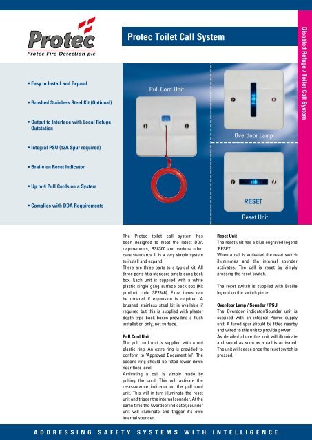
The <strong>Protec</strong> toilet call system has<br />
been designed to meet the latest DDA<br />
requirements, BS8300 and various other<br />
care standards. It is a very simple system<br />
to install and expand.<br />
There are three parts to a typical kit. All<br />
three parts fit a standard single gang back<br />
box. Each unit is supplied with a white<br />
plastic single gang surface back box (Kit<br />
product code SP2846). Extra items can<br />
be ordered if expansion is required. A<br />
brushed stainless steel kit is available if<br />
required but this is supplied with plaster<br />
depth type back boxes providing a flush<br />
installation only, not surface.<br />
Pull Cord Unit<br />
The pull cord unit is supplied with a red<br />
plastic ring. An extra ring is provided to<br />
conform to ‘Approved Document M’. The<br />
second ring should be fitted lower down<br />
near floor level.<br />
Activating a call is simply made by<br />
pulling the cord. This will activate the<br />
re-assurance indicator on the pull cord<br />
unit. This will in turn illuminate the reset<br />
unit and trigger the internal sounder. At the<br />
same time the Overdoor indicator/sounder<br />
unit will illuminate and trigger it’s own<br />
internal sounder.<br />
Reset Unit<br />
The reset unit has a blue engraved legend<br />
‘RESET’.<br />
When a call is activated the reset switch<br />
illuminates and the internal sounder<br />
activates. The call is reset by simply<br />
pressing the reset switch.<br />
The reset switch is supplied with Braille<br />
legend on the switch piece.<br />
Overdoor Lamp / Sounder / PSU<br />
The Overdoor indicator/Sounder unit is<br />
supplied with an integral Power supply<br />
unit. A fused spur should be fitted nearby<br />
and wired to this unit to provide power.<br />
As detailed above this unit will illuminate<br />
and sound as soon as a call is activated.<br />
The unit will cease once the reset switch is<br />
pressed.<br />
ADDRESSING SAFETY SYSTEMS WITH INTELLIGENCE
RED WHEN<br />
ACKNOWLEDGED<br />
Disabled Refuge / <strong>Toilet</strong> <strong>Call</strong> <strong>System</strong><br />
Connection Diagram<br />
230v AC<br />
Technical Information<br />
Disabled Refuge Loop<br />
REFUGE STATION<br />
Interfacing to a Disabled Refuge <strong>Call</strong> system<br />
The <strong>Protec</strong> toilet call system can be interfaced with the <strong>Protec</strong><br />
range of Disabled Refuge <strong>Call</strong> equipment. A CAT5 STP cable<br />
should be wired from the overdoor Lamp/Sounder/PSU unit to<br />
the nearby Disabled Refuge outstation or loop node. The loop<br />
interface card within the outstation or loop node back box is<br />
supplied with terminals for this connection.<br />
This is an extremely cost effective way of reducing cable costs.<br />
The Disabled refuge loop cable is used to bring the toilet call<br />
activation back to the Control Panel. This will be displayed as<br />
text on the LCD display on the Control Panel, and the internal<br />
buzzer will sound.<br />
N<br />
L<br />
E<br />
CALL / ANSWER<br />
OVERDOOR LAMP /<br />
SOUNDER / PSU<br />
0V<br />
12V<br />
Use CAT 5 STP cable for ALL low voltage wiring.<br />
DO NOT USE ‘TWIN & EARTH’ or other rigid cable types<br />
X2<br />
X1<br />
0V<br />
12V<br />
X2<br />
X1<br />
0V<br />
12V<br />
RESET<br />
UNIT<br />
X1<br />
0V<br />
12V<br />
X1<br />
0V<br />
12V<br />
PULL<br />
CORD<br />
UNIT<br />
X1<br />
0V<br />
12V<br />
To next pull cord<br />
Typical Wiring Schematic<br />
Ceiling Pull Cord 3 Core 4 Core Overdoor Lamp/Sounder/PSU<br />
Reset/Sounder<br />
to be 1200mm<br />
max above<br />
floor<br />
Note: CAT 5 STP type cable should be used for the<br />
3 core and 4 core interlink wiring. Twin and Earth or<br />
similar rigid type cables should never be used.<br />
1st Ring to be 100mm from floor<br />
2nd Ring to be between 800/1000mm From floor<br />
Company Policy is one of continuous improvement, we reserve the right to change specification without prior notice<br />
<strong>Protec</strong> <strong>Fire</strong> <strong>Detection</strong> Plc, <strong>Protec</strong> House, Churchill Way, Nelson, Lancashire, BB9 6RT<br />
Tel: 01282 717171 Fax: 01282 717273 Web: www.protec.co.uk Email: sales@protec.co.uk