

X-band Radar System for Detecting Heart and Respiration Rates
X-band Radar System for Detecting Heart and Respiration Rates
X-band Radar System for Detecting Heart and Respiration Rates
- No tags were found...

You also want an ePaper? Increase the reach of your titles
YUMPU automatically turns print PDFs into web optimized ePapers that Google loves.
X-<strong>b<strong>and</strong></strong> <strong>Radar</strong> <strong>System</strong><br />
<strong>for</strong> <strong>Detecting</strong> <strong>Heart</strong> <strong>and</strong> <strong>Respiration</strong> <strong>Rates</strong><br />
Jee-Hoon Lee, Yun-Taek Im, <strong>and</strong> Seong-Ook Park<br />
Korea Advanced Institute of Science <strong>and</strong> Technology, Daejeon, Korea<br />
Abstract—This paper proposes an X-<strong>b<strong>and</strong></strong> Doppler radar system<br />
to detect heart <strong>and</strong> respiration of human far away. Through the<br />
idea of a reverse sense of rotation when the reflecting surface is<br />
perfectly conducting, it is shown that the detecting property of<br />
the system can be effectively improved by using antennas that<br />
have a reverse polarization. This bistatic radar system can be<br />
used in non-invasively sensing bio signals such as respiration <strong>and</strong><br />
heart rates with the periodic movement of skin <strong>and</strong> muscle near<br />
the heart.<br />
Keywords-heart rate; X-<strong>b<strong>and</strong></strong>; array antenna; polarization;<br />
I. INTRODUCTION<br />
Wireless bio-signal detection is the recent tendencies in the<br />
medical industry, <strong>and</strong> research <strong>for</strong> sensing bio-signal continues<br />
to rise. The remote sensing of person using RF system is<br />
profitable in cost aspects compared with expensive medical<br />
instruments. Because the sensing system is easy to h<strong>and</strong>le, even<br />
ordinary person who is not instructed about usage of the<br />
instruments can use it. Until now, bio-detecting system can<br />
measure within short range. We proposed radar system to<br />
detect heart <strong>and</strong> respiration rates of human 10m away from<br />
antenna using a high gain array antenna <strong>and</strong> a frequency<br />
synthesizer which has a low phase-noise characteristic.<br />
power divider, mixer, <strong>and</strong> low noise amplifier (LNA). The<br />
frequency synthesizer output power at an operating frequency<br />
of 10 GHz is 8 dBm. This source signal is divided using a<br />
power divider. One of them is applied to the LO port of the<br />
mixer with about 4.5 dBm, which includes the line loss, <strong>and</strong><br />
the other is entered into the RHP antenna after power amplifier<br />
whose gain 20dB. The received signal is amplified in the<br />
LNA, which has a gain of 9 dB <strong>and</strong> a 3.3 dB noise figure. This<br />
signal is entered into the RF port of the mixer <strong>and</strong> mixed with<br />
the LO signal. Finally, Doppler frequency is entered to<br />
base<strong>b<strong>and</strong></strong> part. We can check the power level at each block<br />
including the transmitted <strong>and</strong> received power at the antennas<br />
varying with the distance between antenna <strong>and</strong> target.<br />
II.<br />
RADAR SYSTEM<br />
A. The Basic Concept of the <strong>System</strong><br />
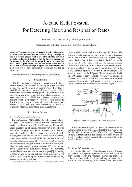
The configuration of X-<strong>b<strong>and</strong></strong> Doppler radar system is shown<br />
in Figure 1. To improve isolation between transmitter <strong>and</strong><br />
receiver, we have separated Tx <strong>and</strong> Rx antenna. For metallic<br />
target, circularly or elliptically polarized waves are reflected<br />
back after changing the polarization sense. In a dielectric<br />
material, circularly polarized waves are reflected back,<br />
changing the axial ratio as well as its sense, which eventually<br />
causes polarization mismatch if Tx <strong>and</strong> Rx antennas have<br />
opposite polarization sense [1]. This is a useful method to<br />
eliminate noise-like targets in the microwave detection system<br />
when the main target is a metallic object. CP waves are not<br />
always required to discriminate targets, but elliptically<br />
polarized waves can also be used to sort targets [2]. According<br />
to these principles, we can achieve better sensitivity of the<br />
radar system using the opposite polarization of transmitting<br />
antenna <strong>and</strong> receiving antenna.<br />
The radar system consists of a frequency synthesizer,<br />
Figure 1. The block diagram of CW Doppler radar system.<br />
In the base<strong>b<strong>and</strong></strong> part, the IF signals are amplified in the<br />
instrumentation amplifier (INA), <strong>and</strong> the HPF then removes the<br />
DC in order to prevent a DC offset. The high frequency<br />
included in the IF signal is then filtered out at the LPF, <strong>and</strong> the<br />
signal is displayed on the computer after converting the digital<br />
signal at the A/D converter.<br />
B. Series-fed Array Antenna<br />
A series-fed elliptically polarized array antenna is designed<br />
<strong>for</strong> X-<strong>b<strong>and</strong></strong> radar system. Symmetrical series feeding at the<br />
array antenna center <strong>and</strong> truncated patches are applied to<br />
reduce side lobe levels (SLL) by modeling the array factor.<br />
Radiation from the feeding line is another source of side lobe
degradation although it has a small effect. Thus, the feed line<br />
should be as short as possible. The feeding point is positioned<br />
at the array antenna center to minimize radiation from it. Figure<br />
2 shows the antenna feeding arrangement <strong>and</strong> the structures.<br />
The design parameters are listed in Table 1. The inter element<br />
spacing (D1 <strong>and</strong> D2) are about 0.7 λ 0 so as to maintain the<br />
same phase condition. The center spacing is λ g /2 to ensure the<br />
same input impedance in the left series <strong>and</strong> right series. Figure<br />
2(a) <strong>and</strong> (b) show the center feed structure with a matching<br />
stub in a two-dimensional series feed array. A truncated patch<br />
element <strong>for</strong> a polarized wave is shown in Figure 2(c).<br />
Figure 3. The fabricated antenna (a) RHP <strong>and</strong> LHP antenna<br />
(b) the center feed point with the matching stub<br />
Figure 2. (a) Proposed array antenna structure<br />
(b) feed point with a matching stub (c) series-fed patch<br />
TABLE I.<br />
DESIGN PARAMETERS (mm)<br />
D1 D2 L1 L2 W1 F1<br />
20.5 21.5 20.375 10.125 1.5 3<br />
F2 F3 F4 F5 P1 P2<br />
2 5 6 3 9.8 1.28<br />
Figure 3 shows the fabricated antennas. It is fabricated<br />
on a substrate with a dielectric constant 2.2 <strong>and</strong> a<br />
thickness of 0.508 mm. The measured gain is 24.8 dBi.<br />
The SLLs are -16 <strong>and</strong> -19 dB in the zx-plane (ф=0°) <strong>and</strong><br />
the yz-plane (ф=90°). The measured axial ratio is shown<br />
in Figure 4(d). The <strong>b<strong>and</strong></strong>width is more than 2% at 10 GHz<br />
as shown in Figure 4 (c).<br />
Figure 4. Simulation <strong>and</strong> measurement<br />
(a) zx-plane (ф=0°) (b) yz-plane (ф=90°) (c) returen loss (d) axail ratio<br />
C. Frequency Synthesizer<br />
Phase noise is the important specification of a Doppler<br />
radar system. Since the motion signal is modulated on the<br />
carrier as a phase modulation, phase noise manifests itself as<br />
amplitude noise on the output. So, a frequency synthesizer<br />
which has a low phase noise characteristic has been proposed.<br />
Figure 5 shows the block diagram of frequency synthesizer.
Human Resource Training Project <strong>for</strong> Regional Innovation.<br />
(No.20080702123415)<br />
Figure 5. The block diagram of frequency synthesizer.<br />
TABLE II.<br />
SPECIFICATION OF FREQUENCY SYNTHESIZER<br />
Output<br />
Frequency<br />
Output Power<br />
10GHz<br />
5.5dBm<br />
Offset<br />
100MH<br />
z<br />
Phase Noise<br />
Typical<br />
-78 dBc/Hz<br />
Harmonic Level -20 dBc 1kHz -93 dBc/Hz<br />
Spurious Level -80 dBc 10kHz -105 dBc/Hz<br />
Operating Power<br />
12V,<br />
450mA<br />
100kHz<br />
-120 dBc/Hz<br />
III. MEASUREMT RESULTS<br />
The male, 30 years in age, sat on a chair with clothing on,<br />
maintaining a straight posture. The antenna was located 10m<br />
away, focusing on the chest. In Figure 6, the top trace is the<br />
respiration signals, the second trace is the heart signals. Unit of<br />
x-axis is time [sec] <strong>and</strong> unit of y-axis is voltage [mV]. We can<br />
obtain the respiration <strong>and</strong> heart signals after filtering the raw<br />
signal within 0.03-0.6 Hz <strong>and</strong> 0.6-3.3 Hz, respectively. By<br />
comparing the heart rates with the ECG signal’ peak position,<br />
we can verify that the period of the ECG’s peak time is<br />
consistent with the heartbeat.<br />
IV. CONCLUSIONS<br />
The wireless bio-signal detection system has many<br />
applications such as remote medical examination, portable vital<br />
sign sensing within cellular phone, decision either life or death<br />
of buried person, detection of invader, etc [4]. In this paper, we<br />
verified the efficiency of the Doppler radar system using<br />
polarization selective series-fed array antennas <strong>and</strong> measured<br />
the respiration <strong>and</strong> heart rates. This system can potentially be<br />
used in ubiquitous home networking including remote medical<br />
examinations <strong>and</strong> treatment.<br />
ACKNOWLEDGMENT<br />
This research was financially supported by the Ministry of<br />
Education, Science Technology (MEST) <strong>and</strong> the Korea<br />
Industrial <strong>for</strong> Advancement of Technology (KIAT) through the<br />
Figure 6. The measured respiration <strong>and</strong> heart rates <strong>for</strong>m body to antenna<br />
(a) 5m distance (b) 7m distance (c) 10m distance (d) ECG signal<br />
REFERENCES<br />
[1] C.A. Balanis, Advanced engineering electromagnetics, Wiley, NY.<br />
[2] A. Hendry <strong>and</strong> G.C. McCormick, Deterioration of circular polarization<br />
clutter cancellation in anisotropic precipitation media, Electron Let 10,<br />
1974, 165-166.<br />
[3] I. S. Jacobs <strong>and</strong> C. P. Bean, “Fine particles, thin films <strong>and</strong> exchange<br />
anisotropy,” in Magnetism, vol. III, G. T. Rado <strong>and</strong> H. Suhl, Eds. New<br />
York: Academic, 1963, pp. 271–350.<br />
[4] Amy D. Droitcour, Olga Boric-Lubecke, Victor M. Lubecke, Jenshan<br />
Lin, “0.25μm CMOS <strong>and</strong> BiCMOS single-chip direct-conversion<br />
Doppler radars <strong>for</strong> remote sensing of vital signs”, Solid-State Circuits<br />
Conference, 2002. Digest of Technical Papers. ISSCC. 2002 IEEE<br />
International, Volume: 1 , 3-7 Feb. 2002, Pages:348 - 349 vol


