D1 H.264 M Series DVR User Manual
D1 H.264 M Series DVR User Manual
D1 H.264 M Series DVR User Manual
- No tags were found...

Create successful ePaper yourself
Turn your PDF publications into a flip-book with our unique Google optimized e-Paper software.
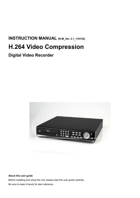
INSTRUCTION MANUAL (N:M_Ver. 2.1_110125)<br />
<strong>H.264</strong> Video Compression<br />
Digital Video Recorder<br />
About this user guide<br />
Before installing and using this unit, please read this user guide carefully.<br />
Be sure to keep it handy for later reference.
Safety Precautions<br />
Explanation of Graphical Symbols<br />
This symbol indicates the presence of important operating and<br />
maintenance (servicing) instructions in the literature accompanying the<br />
product.<br />
This symbol indicates the presence of uninsulated ”dangerous voltage”<br />
within the product’s enclosure that may be of sufficient magnitude to<br />
constitute a risk of electric shock to persons.<br />
WARNING<br />
To reduce a risk of fire or electric shock, do not expose this product to rain or moisture.<br />
CAUTION<br />
Changes or modifications not expressly approved by the manufacturer may void the user’s authority to<br />
operate this equipment.<br />
CAUTION<br />
Danger of explosion if battery is incorrectly replaced.<br />
Replace only with the same or equivalent type recommended by the manufacturer.<br />
Discard used batteries according to the manufacturer’s instructions.<br />
2
These precautions must be followed for safety reasons.<br />
Warning<br />
<br />
<br />
<br />
<br />
<br />
<br />
<br />
<br />
<br />
<br />
<br />
Do not use if the unit emits smoke, strange sounds are heard, or odor is emitted.<br />
Make sure the power cable is not damaged.<br />
Make sure there is no dust accumulation on the power plug or the outlet.<br />
Disassembly prohibited<br />
Do not place any foreign objects inside the unit.<br />
Do not place a container holding water or other liquids above the unit when it is connected to<br />
power.<br />
Do not allow the unit to get wet.<br />
Do not use during thunder/thunder storms.<br />
Do not place in an unstable position.<br />
Do not expose to shock or vibration.<br />
Do not use this unit in areas where it is exposed to the possibility of explosion.<br />
Caution<br />
<br />
<br />
<br />
<br />
<br />
<br />
<br />
<br />
<br />
Do not pull on the power cable when removing the power plug from the outlet.<br />
Do not touch the power plug with wet hands.<br />
Do not sit on.<br />
Make sure the cables are connected properly.<br />
Do not place heavy objects on connected units.<br />
Never move this unit while the power is turned on.<br />
Remove the power plug from the outlet when the unit is going to remain unused for long periods of<br />
time.<br />
Do not block the cooling fans or air ducts.<br />
Do not expose to extreme temperatures or humidity changes.<br />
3
Warning<br />
Installation and servicing should be performed only by qualified and experienced personnel.<br />
Turn off the power of the <strong>DVR</strong> when connecting cameras, audio or sensor cables.<br />
The manufacturer is not responsible for any damage caused by improper use of the product or failure to<br />
follow instructions for the product.<br />
The manufacturer is not responsible for any problems caused by or resulting from the user physically<br />
opening the <strong>DVR</strong> for examination or attempting to fix the unit. The manufacturer may not be held liable for<br />
any issues with the unit if the warranty seal is removed.<br />
4
Product Components<br />
The package contains the main unit and its components as specified below. When you purchase the unit,<br />
Please check to ensure the components specified below are included.<br />
<strong>DVR</strong> Set<br />
DVD-RW (option)<br />
Client Software CD<br />
Remote Control (option)<br />
Battery1.5V (AAA x 2EA) (option)<br />
Quick Guide<br />
HDD data power cable<br />
HDD mounting bracket & Screw<br />
DVD-RW mounting bracket & Screw<br />
HDD & DVD-RW fixing screw<br />
Adaptor (DC12V 5A )<br />
& Power Cable (110V or 220V)<br />
Mouse (Option)<br />
Items<br />
4/8/16CH <strong>DVR</strong><br />
DVD-RW version<br />
Basic version<br />
HDD data power cable 1EA 2EA<br />
HDD mounting bracket 1EA 2EA<br />
HDD Mounting bracket screw 4EA 8EA<br />
DVD-RW mounting bracket<br />
1EA<br />
DVD-RW Mounting bracket screw<br />
4EA<br />
X<br />
HDD/DVD-RW fixing screw 8EA 8EA<br />
5
Basic function of the MOUSE<br />
1 : Left button: SELECT function<br />
2 : Wheel: MOVEMENT function on a drop-down menu<br />
Mounting the DVD-RW<br />
1. Unfasten the cover of the unit. 2. Fix the DVD-RW mounting bracket to the DVD-RW using the<br />
mounting bracket screws and fix the DVD-RW to the unit<br />
using the DVD-RW fixing screws.<br />
3. Connect the DVD-RW cable to the both of DVD-RW and main board.<br />
6
Mounting the HARD DISK<br />
1. Before installing bracket and screws onto<br />
HDD<br />
2. After installing bracket and screws<br />
onto HDD.<br />
3. Installation HDD and Bracket onto base<br />
case (Inside)<br />
4. Installation HDD and Bracket onto base<br />
case (Outside)<br />
5. After connecting power cable and data<br />
cable with HDD<br />
6. Whole picture after installation HDD<br />
and DVD-RW<br />
7
Compatible HDD Models<br />
Seagate ST32000542AS(Barracuda LP) 2 TB 5900 RPM 32 MB<br />
Seagate ST31000340SV(Surveillance) 1 TB 7200 RPM 32 MB<br />
Seagate ST3100528AS(Barracuda) 1 TB 7200 RPM 32 MB<br />
Seagate ST3500830SCE 500 GB 7200 RPM 8 MB<br />
Seagate ST3500418AS(Barracuda) 500 GB 7200 RPM 16 MB<br />
Seagate ST3500410AS(Barracuda) 500 GB 7200 RPM 16 MB<br />
Seagate ST3250410AS(Barracuda) 250 GB 7200 RPM 16 MB<br />
Seagate ST3250310SV(Surveillance) 250 GB 7200 RPM 8 MB<br />
Seagate ST3250318AS(Barracuda) 250 GB 7200 RPM 8 MB<br />
Seagate ST3160815AS(Barracuda) 160 GB 7200 RPM 8 MB<br />
HITACHI HDS722020ALA330 2 TB 7200 RPM 32 MB<br />
HITACHI HDS721010KLA330 1 TB 7200 RPM 32 MB<br />
HITACHI HDT721010SLA360 1 TB 7200 RPM 16 MB<br />
HITACHI HDS721010CLA332 1 TB 7200 RPM 32 MB<br />
HITACHI HDS721050CLA362 500 GB 7200 RPM 16 MB<br />
HITACHI HDP725050GLA360 500 GB 7200 RPM 16 MB<br />
HITACHI HDS721032CLA362 320 GB 7200 RPM 16 MB<br />
HITACHI HDS721025CLA382 250 GB 7200 RPM 8 MB<br />
HITACHI HDT721025SLA380 250 GB 7200 RPM 8 MB<br />
HITACHI HDP725025GLA380 250 GB 7200 RPM 8 MB<br />
Western Digital WD20EADS 2 TB 7200 RPM 32 MB<br />
Western Digital W<strong>D1</strong>0EACS 1 TB 7200 RPM 16 MB<br />
Western Digital WD5000AACS 500 GB 7200 RPM 16 MB<br />
Western Digital WD2500AAKS 250 GB 7200 RPM 16 MB<br />
NOTICE<br />
The brands and models of all HDD should be the same. If the brands and models of each HDD are different<br />
with others, the <strong>DVR</strong> may not recognize HDD.<br />
8
Specifications<br />
Input<br />
Video<br />
Output<br />
Audio<br />
ITEM N-0440M N-0840M N-1640M<br />
Channel, Input Level 4CH, Composite 8CH, Composite 16CH, Composite<br />
Signal Format<br />
NTSC/PAL<br />
Video Loss Check<br />
Yes<br />
XGA Resolution<br />
1 VGA (1024x768), 1 CVBS, Dual Display<br />
XGA Resolution<br />
1 VGA (1024x768), 1 Spot<br />
SXGA Resolution<br />
1 VGA (1280x1024), 2 Spot<br />
Input & Output<br />
4 CH Line input & 1 CH Line output<br />
Audio Codec G.711<br />
Alarm<br />
Sensor Input (NC/NO Selectable)<br />
4ch (NC/NO Selectable)<br />
Alarm Output<br />
1 Alarm out by Sensor, Motion and Video Loss<br />
Compression <strong>H.264</strong><br />
Multi-operation<br />
QUADPLEX (Playback/Record/Network/Backup)<br />
<strong>D1</strong> 120fps 120fps 120fps<br />
NTSC Half <strong>D1</strong> 120fps 240fps 240fps<br />
Resolution<br />
CIF 120fps 240fps 480fps<br />
<strong>D1</strong> 100fps 100fps 100fps<br />
Record<br />
PAL Half <strong>D1</strong> 100fps 200fps 200fps<br />
CIF 100fps 200fps 400fps<br />
Recording quality grade<br />
ECONOMY, STANDARD, HIGH, SUPER, ULTRA<br />
Recording Mode<br />
Continuous / Schedule / Motion/ Sensor/ <strong>Manual</strong><br />
Motion Detection<br />
Motion detection setup by Grid<br />
Recording by channel’s Resolution<br />
Yes<br />
Pre Recording<br />
1 fps for 10 seconds before an event<br />
Post Recording<br />
10 seconds to 3 minutes after an event<br />
Display Frame Rate ( /Sec) NTSC: 30fps/ch, 60 fields / PAL: 25fps/ch, 50 fields<br />
Multi-Decoding 1, 4 1, 4, 8 1, 4, 8, 16<br />
Playback Playback Speed<br />
Single channel × 2, 4, 8, 16<br />
Multi-channels × 2, 4 × 2, 4 × 2<br />
Search Mode<br />
Timeline, Event, Archive, Log<br />
Interface Type<br />
Serial ATA<br />
Capacity of 1<br />
Storage<br />
HDD<br />
HDD<br />
2TB<br />
Internal HDD No.<br />
1 (2: W/O DVD-RW)<br />
File system<br />
NaFS<br />
9
USB Port 2 (Front 1, Rear 1)<br />
<strong>User</strong> I/F<br />
Serial port<br />
Network<br />
Network<br />
Access<br />
Features<br />
USB Flash drive<br />
Built-in DVD-RW<br />
Backup<br />
Huge Backup<br />
Network<br />
Menu Display<br />
Input Method<br />
Console<br />
PTZ control & Keyboard <strong>DVR</strong> control<br />
Termination<br />
Dynamic DNS<br />
Network Interface<br />
Dual Encoding for Network Streaming<br />
Auto Port Forward<br />
Client Software (1:1)<br />
Web viewer (1:1)<br />
Multi-sites Monitoring System (1:n)<br />
DLS (Day Light Saving)<br />
Quick Setup<br />
S.M.A.R.T<br />
Internal Beep<br />
Multi-Language<br />
S/W Upgrade<br />
NTP<br />
3G Mobile<br />
POS / ATM<br />
Video & Still Image<br />
Video & Still Image<br />
Yes (up to 24 hours)<br />
Video & Still Image<br />
New GUI<br />
Front buttons, Remote control, Mouse, Keyboard controller<br />
1 RS-232C (9pin D-SUB connector)<br />
1 RS-485<br />
Yes<br />
Yes (Free DDNS)<br />
10/100/1000 base-T Ethernet (RJ-45)<br />
Yes (CIF 120/100fps)<br />
Yes<br />
Live, Search, Backup, PTZF Camera Control, Remote Setup<br />
Live, Search, Backup, PTZF Camera Control<br />
Live, Search, Backup, PTZF Camera Control, Remote Setup<br />
Yes<br />
Yes<br />
Yes<br />
By Alarm, Motion, Video Loss, HDD error<br />
Yes<br />
USB Flash drive, Remote S/W Upgrade (TBD)<br />
Yes<br />
Yes (Exclusive Viewer)<br />
Yes (TBD)<br />
Power<br />
source<br />
Power Supply Voltage<br />
DC 12V 5A<br />
Allowable operation temperature During operation<br />
5°C - 40°C, During storage: -10°C - +50°C<br />
Allowable operation humidity 0 - 90 %<br />
Weight Unit Weight (Gross weight) 4.1Kgs (6.2Kgs) / 9Lbs(13.6Lbs)<br />
Dimension Unit Dimension (W x H x D) 380mm x 340mm x 72mm / 14.9” x 13.3” x 28”<br />
Please note that specifications and unit exterior design are subject to change without notification<br />
10
Table of Contents<br />
1. Main Features ............................................................................................................ 13<br />
2. Name, Function and Connection ................................................................................ 15<br />
2-1. Front Panel ................................................................................................................................... 15<br />
2-2. Rear Panel ................................................................................................................................... 17<br />
2-3. Remote control ............................................................................................................................. 18<br />
3. Setting up the <strong>DVR</strong> ..................................................................................................... 19<br />
3-1. Setup – Main Screen .................................................................................................................... 19<br />
3-2. Setup – Display Mode .................................................................................................................. 23<br />
3-3. Setup – Recording Mode .............................................................................................................. 24<br />
3-3-1. Recording Schedules ................................................................................................................ 26<br />
3-4. Setup – Device Mode ................................................................................................................... 27<br />
3-4-1. ALARM-OUT ............................................................................................................................. 28<br />
3-4-2 SPOT-OUT setup ....................................................................................................................... 29<br />
3-4-3 PTZ Setup .................................................................................................................................. 29<br />
3-4-4. Motion Zone Setup .................................................................................................................... 31<br />
3-5. Setup – Storage Mode .................................................................................................................. 32<br />
3-6. Setup – System Mode .................................................................................................................. 33<br />
3-7. Setup – SECURITY Mode ............................................................................................................ 37<br />
3-8. Setup – Network Mode ................................................................................................................. 39<br />
3-8-1. Network Types .......................................................................................................................... 41<br />
3-8-1-1. DHCP ..................................................................................................................................... 41<br />
3-8-1-2. ADSL (PPPoE) ....................................................................................................................... 41<br />
3-8-1-3. LAN ........................................................................................................................................ 42<br />
3-8-2. DDNS ........................................................................................................................................ 43<br />
3-8-3. Network Ports ............................................................................................................................ 44<br />
3-8-4. Network Stream ......................................................................................................................... 46<br />
3-9. Setup - CONFIG Mode ................................................................................................................. 46<br />
3-10. Quick Setup ................................................................................................................................ 48<br />
3-11. Saving Setup .............................................................................................................................. 49<br />
4. Live, Search and Playback ......................................................................................... 50<br />
4-1. Live Viewing Screen ..................................................................................................................... 50<br />
4-2. SEARCH Screen .......................................................................................................................... 52<br />
4-2-1. TIME-LINE Search .................................................................................................................... 52<br />
4-2-2. Event Search ............................................................................................................................. 53<br />
4-2-3. Go To First Time ........................................................................................................................ 53<br />
4-2-4. Go To Last Time ........................................................................................................................ 54<br />
11
4-2-5. Go To Specific Time ................................................................................................................... 54<br />
4-2-6. Archive Search .......................................................................................................................... 54<br />
4-2-7. Log Search ................................................................................................................................ 55<br />
4-3. Play mode .................................................................................................................................... 55<br />
5. PTZ Control ................................................................................................................... 56<br />
6. Back up ......................................................................................................................... 58<br />
6-1. Still Image backup onto USB flash memory .................................................................................. 58<br />
6-2. Video backup onto USB flash memory ......................................................................................... 58<br />
6-3. Transferring still images or video from the ARCHIVE list .............................................................. 59<br />
6-4. Playback of Backup Video ............................................................................................................ 60<br />
7. Upgrading Firmware ...................................................................................................... 61<br />
8. Network access using the Exclusive network viewer, UMS single .................................. 62<br />
8-1. PC requirements .......................................................................................................................... 62<br />
8-2. Installing the network viewer ......................................................................................................... 62<br />
8-3. Live monitoring mode and functions. ............................................................................................ 63<br />
8-4. Bi directional audio ....................................................................................................................... 65<br />
8-5. Remote search mode and functions ............................................................................................. 65<br />
8-6. PC System configuration .............................................................................................................. 68<br />
9. Network access using the Exclusive network viewer, UMS multi ................................... 71<br />
9-1. Overview ...................................................................................................................................... 71<br />
9-2. Minimum PC requirements ........................................................................................................... 71<br />
9-3. Installing the program ................................................................................................................... 71<br />
9-4. Live Window ................................................................................................................................. 72<br />
9-4-1. Main user interface ........................................................................................... 73<br />
9-4-2. Control buttons ................................................................................................. 73<br />
9-5. Search and Playback Window ...................................................................................................... 74<br />
9-5-1. Main user interface ........................................................................................... 74<br />
8-5-2. Main control panel ............................................................................................ 75<br />
9-6. Setup of UMS Multi Client............................................................................................................. 77<br />
9-6-1. General ............................................................................................................ 77<br />
9-6-2. Event ................................................................................................................ 78<br />
9-6-3. Record ............................................................................................................. 79<br />
9-6-4. OSD ................................................................................................................. 80<br />
9-6-5. Language ......................................................................................................... 80<br />
9-6-6. About ................................................................................................................ 81<br />
9-7. Remote Setup .............................................................................................................................. 81<br />
9-7-1. Setting the Display ........................................................................................... 81<br />
9-7-2. Record ............................................................................................................. 82<br />
9-7-3. Device .............................................................................................................. 83<br />
9-7-4. Storage ............................................................................................................ 86<br />
9-7-5. System ............................................................................................................. 86<br />
12
9-7-6. Security ............................................................................................................ 90<br />
9-7-7.Network ............................................................................................................. 91<br />
9-8. Operation ..................................................................................................................................... 92<br />
9-8-1. Addition, Delete, and modify of <strong>DVR</strong> sites ........................................................ 92<br />
9-8-2. Connect and Disconnect .................................................................................. 94<br />
9-8-3. Still-image capture during Live ......................................................................... 96<br />
9-8-4. Recording video on local PC during Live .......................................................... 96<br />
9-8-5. Local Playback and Remote Playback ............................................................. 97<br />
9-8-6. AVI Backup during playback ............................................................................. 99<br />
10. Network – By an web-browser viewer ........................................................................ 101<br />
APPENDIX: How to connect network............................................................................... 104<br />
A. How to set IP address of the <strong>DVR</strong> and open TCP port of the router .......................................... 104<br />
B. How to access <strong>DVR</strong> from Remote PC ...................................................................................... 106<br />
C. How to access <strong>DVR</strong> with iPhone ................................................................................................. 109<br />
D. How to access <strong>DVR</strong> with Android ................................................................................................ 110<br />
1. Main Features<br />
<strong>H.264</strong> Video compression<br />
Reliable File system<br />
2 Spots (Live and Event Pop-up)<br />
High quality VGA (1280X1024)<br />
13
4channel audio recording<br />
Individual channel operation<br />
Motion detection<br />
Automatic video input and video loss detection<br />
Covert camera operation provides enhanced security<br />
Built-in PTZF camera control<br />
Easy and simple user interface<br />
Easy scheduler<br />
14
Easy software upgrade<br />
Instant and convenient backup via USB flash drive, network or DVD-RW<br />
Exclusive file format backup<br />
AVI backup<br />
Various ways of network access via Network client software, Web-viewer, CMS, UMS(Multi-site<br />
monitoring software) and Mobile Viewer<br />
2. Name, Function and Connection<br />
2-1. Front Panel<br />
The following information will help you to operate the front panel controls.<br />
Figure 2.1.1. Front panel<br />
15
Table2.1.1. Indication lamps<br />
NO. Name Description<br />
A CH1~16 Indicating that the channel is being recorded.<br />
B HDD Indicating that the system is accessing the hard disk.<br />
C ALARM Indicating that when sensor(s) is/are triggered or motion is detected.<br />
D NETWORK Indicating that when Network client connects through the network.<br />
E BACKUP Indicating that USB or DVD-RW storage device is stored images or<br />
video.<br />
F POWER Indicating that the system is switched on.<br />
Table 2.1.2. Front panel buttons<br />
NO Name Description<br />
1 Channel keys. For channel 10, press the 0 key. For channel 11, press<br />
the +10 and 1 key. For channel 16, press the +10 and 6 key.<br />
2 Press to rewind the footage in playback mode.<br />
3 Press to select audio mode such as SINGLE, MIX and MUTE.<br />
MUTE- All of 4 channels.<br />
SINGLE- Highlighted channel only.<br />
MIX- All of 4 channels.<br />
4 Jump/Step backward. In playback mode, the playback position moves<br />
60 seconds backward.<br />
5 Press to fast forward the footage in playback mode.<br />
6 Press to enable/disable ALARM operation.<br />
7 Jump/Step forward. In playback mode, the playback position moves<br />
60 seconds forward.<br />
8 Press to start or stop manual recording.<br />
9 Press to go to SEARCH menu in live display mode.<br />
10 Press to play/pause the footage in playback mode.<br />
11 Press to enter SETUP menu.<br />
12 Enable/disable the automatic sequence of display of channels in full<br />
screen, quad, 9-split display mode.<br />
16
13 Press to control Pan/Tilt/Zoom operations.<br />
14 Press to capture video in jpeg format in live or playback mode.<br />
15 ◀(LEFT) Press to move left or to change the values in Setup mode.<br />
It is also used as the number 4 when entering password.<br />
16 ▲(UP) Press to move up the menu in Setup mode.<br />
It is also used as the number 1 when entering password.<br />
17 ▶(RIGHT) Press to move right or to change the values in Setup mode.<br />
It is also used as the number 2 when entering password.<br />
18 ▼(DOWN) Press to move down the menu in Setup mode.<br />
It is also used as the number 3 when entering password.<br />
19 Press to select desired menu item or to store the setup value.<br />
20 Press for temporary storage of the changed value or to return to the<br />
previous menu screen.<br />
21 USB Port To archive still-image or video into a USB memory or upgrade<br />
firmware with USB memory stick, connect a USB memory to the USB<br />
terminal.<br />
22 OPEN To open and close the insert tray, press the button.<br />
/CLOSE<br />
23 DVD drive To save video, insert a CD-R/DVD-R<br />
2-2. Rear Panel<br />
N-0440M<br />
N-0840M<br />
17
N-1640M<br />
Table 2.2.1. Rear panel connections<br />
NO Connection Purpose<br />
1 VIDEO IN 16 connectors for video input. (NTSC/PAL)<br />
2 CVBS Spot out 1: Split screens with live images.<br />
Spot out 2: One channel screen with an event image.<br />
3 AUDIO IN 4 connectors for audio input.<br />
4 AUDIO OUT 1 connector for audio output.<br />
5 VGA Connector for VGA monitor.<br />
6 RS-232 For engineering use only.<br />
7 ETHERNET RJ-45 connector for LAN connection.<br />
8 SENSOR IN 4 connectors for sensor device connection.<br />
9 ALARM OUT 1 connector for alarm device connection.<br />
Provides simple On/Off switching by using relay. 0.5A/125V,<br />
1A/30V<br />
10 RS-485 RS-485 control terminal<br />
11 POWER SOCKET Connect DC12V 5A Adaptor<br />
12 USB Port To archive still-image or video into a USB memory or<br />
upgrade firmware with USB memory stick, connect a USB<br />
memory to the USB terminal.<br />
13 e-SATA Port 1 connector for External SATA<br />
14 COOLING FAN<br />
2-3. Remote control<br />
1 ID: When a remote control ID number is set in <strong>DVR</strong>, press it before number.<br />
2 REC: To start and stop manual recording.<br />
18
3 Number: To select channel (1, 2, 3, & 4) or to enter <strong>DVR</strong> ID number.<br />
4 F/REW: During playback - To move the playback position 60 seconds backward.<br />
During pause - To move the playback position 1 frame backward.<br />
5 F/ADV: During playback - To move the playback position 60 seconds forward.<br />
During pause - To move the playback position moves 1 frame forward.<br />
6 REW: To rewind the footage at 1x, 2x, 4x, and 8x speed during playback.<br />
7 PLAY/PAUSE: To play or to pause the footage in playback mode.<br />
8 FF: To fast forward the footage at 1x, 2x, 4x, and 8x speeds during playback.<br />
9 Control button: Press to move the menu items or select channel.<br />
10 SETUP: To launch SETUP menu.<br />
11 SEARCH: To go to the search menu.<br />
12 ESC: During setting - To return to previous menu screen.<br />
During playback - To exit from playback<br />
<br />
<br />
System Lock – to lock a system when pressing ESC button for 5 seconds.<br />
System Unlock – to unlock a system when pressing ESC button for 5 seconds.<br />
13 BACKUP: To start operations of backup in live or playback mode. (The same function button as<br />
CAPTURE on the front panel of <strong>DVR</strong>)<br />
14 SEQ: To start auto sequencing of the screen in full screen mode. (Toggle)<br />
3. Setting up the <strong>DVR</strong><br />
The following sections detail the initial setup of a <strong>DVR</strong>.<br />
3-1. Setup – Main Screen<br />
When booting a system at first, the following messages display. After initializing, select a language and set<br />
the time.<br />
To enter the setup menu, select a right button of the mouse or press the SETUP button on the remote<br />
control.<br />
19
Table 3.1.1. Setup menu tree<br />
Then password input screen will be displayed. <strong>User</strong> can select a password by pressing a small square box<br />
next to a password input box. The factory default password is 1111. It is highly recommended to assign a<br />
new password to protect the system. <strong>User</strong> can assign a new password in SECURITY setup menu.<br />
<br />
<br />
DISPLAY<br />
– OSD<br />
– OSD CONTRAST<br />
– SEQUENCE<br />
– SEQUENCE DWELL TIME<br />
– CHANNEL<br />
- NAME<br />
- COVERT<br />
- BRIGHTNESS<br />
- CONTRAST<br />
- HUE<br />
- SATURATION<br />
RECORD<br />
– CHANNEL<br />
- RESOLUTION<br />
- FRAME RATE<br />
20
- QUALITY<br />
- RECORDING<br />
- SENSOR RECORDING<br />
- PRE RECORD<br />
- POST EVENT RECORD<br />
- AUDIO<br />
- SCHEDULE<br />
DEVICE<br />
– VIDEO OUTPUT<br />
– ALARM OUT<br />
- SENSOR IN<br />
- MOTION ON<br />
- VIDEO LOSS ON<br />
- ALARM DURATION<br />
- ERROR ALARM<br />
– PTZ<br />
- CHANNEL<br />
- NAME<br />
- SPEED<br />
- ID<br />
– SPOT OUT<br />
- SPOT OUT 1<br />
- SPOT OUT 2<br />
– CHANNEL<br />
- MOTION ZONE<br />
- MOTION SENSITIVITY<br />
– KEY TONE<br />
– REMOTE CONTROLLER ID<br />
– SENSOR<br />
- TYPE<br />
STORAGE<br />
– OVERWRITE<br />
– DISK FORMAT<br />
– DISK INFO<br />
– RECORDING LIMIT<br />
- RECORDING LIMIT DAYS<br />
– S.M.A.R.T<br />
SYSTEM<br />
– <strong>DVR</strong>-ID<br />
21
– DESCRIPTION<br />
– LANGUAGE<br />
– DATE FORMAT<br />
– SET DATE & TIME<br />
- DAYLIGHT SAVING<br />
- SET DATE & TIME<br />
– CLIENT ACCESS<br />
– BANDWIDTH SAVING<br />
– SEND EMAIL<br />
– NTP<br />
SECURITY<br />
– USER AUTHENTICATION (ADMIN, NETWORK, USER1, USER2, USER3)<br />
– USER PASSOWRD<br />
NETWORK<br />
– NETWORK TYPE (DHCP, ADSL, LAN)<br />
– DDNS<br />
- DDNS SERVER 1<br />
- DDNS SERVER 2<br />
– NETWORK PORT<br />
- PORT<br />
- WEB PORT<br />
- AUTO PORT FORWARD<br />
– NETWORK STREAM<br />
- FRAME RATE<br />
- BITRATE<br />
CONFIG<br />
– SAVE SETUP TO A USB<br />
– LOAD SETUP FROM A USB<br />
– LOAD DEFAULT<br />
– LOAD FACTORY DEFAULT<br />
QUICK SETUP<br />
– USE QUICK SETUP<br />
- INPUT DESIRED DAYS<br />
– CUSTOMER SETTINGS<br />
- RESOLUTION<br />
- FRAME RATE<br />
- QUALITY<br />
- RECORDING<br />
- DAYS TO RECORD<br />
– DUAL STREAM<br />
- DUAL RESOLUTION<br />
22
- DUAL FRAME RATE<br />
- DUAL QUALITY<br />
3-2. Setup – Display Mode<br />
Press the SETUP button and select DISPLAY. Then, the DISPLAY menu displays as picture below.<br />
Navigate through the menu items using the mouse or the control button (◀ ▲ ▶ ▼) on the remote control<br />
and change the value of the menu item.<br />
Figure 3.2.1. Display mode setup screen<br />
Item<br />
OSD<br />
OSD CONTRAST<br />
SEQUENCE<br />
SEQ-DWELL TIME<br />
CHANNEL<br />
Table 3.2.1. Menu items in DISPLAY mode setup<br />
Description<br />
Enable/disable on-screen-display.<br />
Set the visibility level of the On Screen Display (OSD).(0~100)<br />
Enable/disable sequential display of video in full screen mode.<br />
Set the dwell time of each, quad or 9 channels display in sequential<br />
display mode.(3-60seconds)<br />
Select a channel for applying the following settings using the mouse or<br />
control button (◀ ▲ ▶ ▼) on the remote control. Press the right<br />
square button to change the setting value of all channels at once.<br />
Press SEL button to change the setting value of all channels at once.<br />
Press a right button of the mouse control just one time if you want to<br />
select an item and please do a double-click if you want to change the<br />
value. Once you select an item, then press OK to set value for all<br />
channels.<br />
(COVERT, BRIGHTNESS,CONTRAST,HUE,SATURATION)<br />
23
NAME Set the channel name. Press the right square button and set the<br />
channel name and select OK using the mouse or the control button (◀<br />
▲ ▶ ▼) on the remote control. The name can be made by 10<br />
characters at most.<br />
COVERT Enable/disable display of the specified video channel in live display<br />
mode.<br />
BRIGHTNESS Change the brightness value of the specified channel. (0~100)<br />
CONTRAST Change the contrast value of the specified channel. (0~100)<br />
HUE Change the hue value of the specified channel. (0~100)<br />
SATURATION Change the saturation value of the specified channel. (0~100)<br />
3-3. Setup – Recording Mode<br />
Press the SETUP button and select RECORD icon. Then, the RECORD menu is displayed as picture below.<br />
Navigate through the menu items using the mouse or the control button (◀ ▲ ▶ ▼) on the remote control<br />
and change the value of the menu item.<br />
24
Figure 3.3.1. Recording mode setup screen<br />
CHANNEL<br />
Menu item<br />
Table 3.3.1. Menu items in Recording mode setup<br />
Description<br />
Select a channel for applying the following settings using the mouse<br />
or the control button (◀ ▲ ▶ ▼) on the remote control. Press the<br />
right square button to change the setting value of all channels at<br />
once. Once you select an item, then press OK to set value for all<br />
channels.<br />
(RESOLUTION, FRAME RATE, QUALITY, RECORDING, PRE<br />
RECORD and POST EVENT RECORD)<br />
RESOLUTION Select one type among CIF, Half <strong>D1</strong> and <strong>D1</strong> using the mouse or the<br />
control button(◀ ▲ ▶ ▼) on the remote control.<br />
FRAME RATE Set the frame rate for the specified channel. The sum of the frame<br />
rate values from each channel cannot exceed the maximum frame<br />
rates for a specific recording resolution.<br />
Typical values of the maximum frame rate for video are as<br />
follows.<br />
CIF Half <strong>D1</strong> <strong>D1</strong><br />
N-0440M 120/100fps 120/100fps 120/100fps<br />
N-0840M 240/200fps 240/200fps 120/100fps<br />
N-1640M 480/400fps 240/200fps 120/100fps<br />
25
QUALITY Select the recording quality for the specified channel. Options are:<br />
Network, Standard, High, Super and Ultra.<br />
RECORDING Assign the recording mode for each channel. Options are:<br />
Continuous, By Motion, By Sensor, By Schedule or Disable.<br />
PRE RECORD Enable/disable pre-event recording. Pre-event recording time is 5<br />
seconds and only intra-frames are recorded for pre-event recording.<br />
POST EVENT Set the post event recording time duration for the specified channel.<br />
RECORD (10~30 seconds)<br />
SENSOR<br />
Enable setting up to 4 sensors for the specified channel using the<br />
RECORDING<br />
mouse or the control button (◀ ▲ ▶ ▼) of the remote control.<br />
AUDIO<br />
Enable/disable audio recording for the specified channel.<br />
Fixed-available on only from channel 1 to channel 4.<br />
SCHEDULE<br />
Set the recording schedule. Press SEL to go to schedule setup<br />
screen.<br />
3-3-1. Recording Schedules<br />
To setup a recording schedule, select SCHEDULE in the RECORD menu. Navigate through the menu<br />
items using the mouse or the control button (◀ ▲ ▶ ▼) on the remote control.<br />
[Channel]: Select the specific channel.<br />
[Setup]: Set up using the left button of the mouse to section under the specific day and time. It can set the<br />
all section under the specific day or time at a time when pressing the specific day or time. It is also<br />
possible to set up recording modes of various type using a Continue(green color), Motion(yellow<br />
color) and Sensor button(red color). It can set easy using a drag-and-drop function of a mouse<br />
control.<br />
[COPY Schedule]: Set the channel 1 schedule and select the square button of CH2 in COPY SCHEDULE<br />
section using the mouse. And, press the COPY button. Then the CH1 schedule is copied to CH2. To<br />
remove the setting value, press the CLEAR button.<br />
26
Figure 3.3.2. Schedule recording setup screen<br />
3-4. Setup – Device Mode<br />
Press the SETUP button and enter the password. Select DEVICE icon and press SEL button to enter the<br />
setup menu item. Then, the device menu is displayed as picture below. Navigate through the menu items<br />
using the mouse or the control button (◀ ▲ ▶ ▼) on the remote control and change the value of the<br />
menu item.<br />
Figure 3.4.1. Device mode setup screen<br />
Item<br />
VIDEO OUTPUT<br />
Table 3.4.1. Menu items in Device Setup screen<br />
Description<br />
Set the VGA resolution 1024x768, 1280x1024 or CVBS output.<br />
The default values are 1024x768 and CVBS on.<br />
27
When it changes the VGA resolution and saves the value, the<br />
system will reboot.<br />
When it changes the VGA resolution to 1280x1024, the CVBS<br />
is set to Off.<br />
ALARM OUT<br />
Set the sensor, motion, and video loss for each alarm.<br />
PTZ<br />
Set the PTZ camera speed, number, type and ID.<br />
SPOT-OUT<br />
Set the all details for spot monitoring. It supports 2 spot-outs.<br />
CHANNEL<br />
Select specified channel for motion zone setup.<br />
MOTION ZONE Select either Full Zone or Partial Zone for motion sensing.<br />
MOTION SENSITIVITY Set the motion sensitivity for the specified channel.<br />
Control the motion sensitivity from 1 to 9.<br />
KEY TONE<br />
Enable/disable key tone.<br />
REMOTE CONTROL ID Select an ID of remote control.<br />
1. Select ID.<br />
2. Press the same number as ID set in <strong>DVR</strong> on a remote<br />
control.<br />
3. Then icon will be displayed on Live screen of <strong>DVR</strong> that<br />
respond to the remote control.<br />
The options are from 0 to 99<br />
SENSOR Select sensor NO from 1 to 4<br />
TYPE Set the type of sensor for the specified channel. Options are:<br />
OFF, N/O (normal open), and N/C (normal closed).<br />
3-4-1. ALARM-OUT<br />
Figure 3.4.2. ALARM-OUT setup screen<br />
Table 3.4.2. Menu item in ALARM-OUT Setup screen<br />
28
Item<br />
Description<br />
ALARM OUT Available NO is just one (1).<br />
SENSOR IN Enable setting up to 1 camera of 4 cameras for each alarm.<br />
MOTION ON Enable setting up to 1 camera of 4 cameras for each alarm.<br />
VIDEO LOSS ON Enable setting up to 1 camera of 4 cameras for each alarm.<br />
ALARM DURATION Set the alarm dwell time from 5 to 60 seconds.<br />
ERROR ALARM Set the error type for the alarm activation. The options are<br />
OFF, ALL, HDD ERROR and VIDEO LOSS.<br />
3-4-2 SPOT-OUT setup<br />
Figure 3.4.3. SPOT-OUT setup screen<br />
Table 3.4.3. Menu item in SPOT-OUT Setup screen<br />
N-0441L supports just 1 Spot Out.<br />
Item<br />
Description<br />
SPOT OUT 1 To use the Spot out function, it has to change CVBS to OFF in a Video<br />
Output menu.<br />
SPOT TYPE Spot out 1 supports FULL type. (1 channel only)<br />
SPOT ON EVENT Enable/Disable display of the channel when an event is active.<br />
SPOT EVENT Set the dwell time for the display of the event activated channel.<br />
DWELL TIME (1-10sec)<br />
SEQUENCE Enable/disable sequential display of spot channel in full screen.<br />
If select ON, spot channel selection screen is displayed.<br />
SEQ-DWEL TIME Set the dwell time for the spot channel display.(1-10sec)<br />
SPOT CHANNEL Select a channel for spot monitoring using the mouse or the control<br />
button (◀ ▲ ▶ ▼) on the remote control and press OK button.<br />
29
N-0840L and N-1640L support up to 2 Spot Outs.<br />
Item<br />
Description<br />
SPOT OUT 1 If the Video Output is set to CVBS On, the Spot Out 1 works as CVBS.<br />
If the Video Output is set to CVBS Off, the Spot Out 1 supports as<br />
Spot Out function and it supports All channel live mode only.<br />
SPOT OUT 2 Regardless the Video Output setting, N-0840L and N-1640L support<br />
Spot Out 2.<br />
SPOT TYPE Spot out 2 supports FULL type. (1 channel only)<br />
SPOT ON EVENT Enable/Disable display of the channel when an event is active.<br />
SPOT EVENT Set the dwell time for the display of the event activated channel.<br />
DWELL TIME (1-10sec)<br />
SEQUENCE Enable/disable sequential display of spot channel in full screen.<br />
If select ON, spot channel selection screen is displayed.<br />
SEQ-DWEL TIME Set the dwell time for the spot channel display.(1-10sec)<br />
SPOT CHANNEL Select a channel for spot monitoring using the mouse or the control<br />
button (◀ ▲ ▶ ▼) on the remote control and press OK button.<br />
3-4-3 PTZ Setup<br />
To control the PTZ functions of the camera, connect a controller to the RS-485 port.<br />
1 Connect the RS-485 cables of PTZ camera to the RS-485 port on the rear panel.<br />
2 Press the PTZ menu button. Then PTZ menu screen is displayed.<br />
30
Figure 3.4.4. PTZ Control Setup Screen<br />
Note: For speed dome cameras that support RS-485, connect them directly to the RS-485 port. If the<br />
camera is controlled with RS-232C, use an RS-485 to RS-232C signal converter.<br />
On the PTZ control setup screen, you can select or set the protocol type of the camera that is the same as<br />
the one installed on the site. If the camera has a specific camera ID, select the camera ID using the mouse<br />
or the control button (◀ ▲ ▶ ▼) of the remote control.<br />
The following options are available on the PTZ setup screen.<br />
CHANNEL (channel number that the PTZ is connected to)<br />
NAME (protocol type)<br />
SPEED (19200, 14400, 9600, 4800, 2400)<br />
ID (0-63)<br />
3-4-4. Motion Zone Setup<br />
Select MOTION ZONE using the mouse or the control button (◀ ▲ ▶ ▼) on the remote control and<br />
select either PARTIAL ZONE or FULL ZONE using the mouse control. The default value is FULL ZONE.<br />
If FULL ZONE is selected, the motion setting screen is not displayed. Only set the level of sensitivity for<br />
MOTION SENSITIVITY.<br />
FULL ZONE: The motion sensor is active on the whole screen.<br />
PARTIAL ZONE: The motion sensor is active in the set detection frame.<br />
Select the sensor detection position using the mouse or the control button (◀ ▲ ▶ ▼) on the remote<br />
control. Then the color of the position which is selected will be changed. And the press the right button of<br />
the mouse or SEL button of the remote control. Press OK button of the SETUP menu to save the setting<br />
value.<br />
31
Figure 3.4.5. Motion Zone selection screen<br />
3-5. Setup – Storage Mode<br />
Press the SETUP button and select STORAGE icon. Then, the STORAGE menu is displayed as picture<br />
below. Navigate through the menu items using the mouse or the control button (◀ ▲ ▶ ▼) on the remote<br />
control and change the value of the menu item.<br />
Figure 3.5.1. STORAGE setup screen<br />
OVERWRITE<br />
Item<br />
DISK FORMAT<br />
Table 3.5.1. Menu items in STORAGE Setup screen<br />
Description<br />
When enabled, the <strong>DVR</strong> will continue recording and<br />
overwrite the oldest existing recorded data once the hard<br />
drive is full. When disabled, recording will stop once the hard<br />
drive is full.<br />
You will have an option YES or NO for the hard drive format.<br />
Caution:<br />
32
We recommend that you archive any data that you may<br />
need in the future before you format the hard drive.<br />
DISK INFO<br />
Hard drive information<br />
RECORDING LIMIT<br />
Enable/disable recording limit.<br />
RECORDING LIMIT DAYS Set the recording limit days.(1- 90 days)<br />
When setting to 1 day, the data will remove by the hour.<br />
S.M.A.R.T<br />
Set the alarm and beep by setting HDD temperature limit.<br />
3-6. Setup – System Mode<br />
Press the SETUP button and select SYSTEM icon. Then, the SYSTEM menu is displayed as picture below.<br />
Navigate through the menu items using the mouse or the control button (◀ ▲ ▶ ▼) on the remote control<br />
and change the value of the menu item.<br />
Figure 3.6.1. SYSTEM Setup Screen<br />
Item<br />
<strong>DVR</strong> ID<br />
Table 3.6.1. Menu items in SYSTEM Setup screen<br />
Description<br />
Set <strong>DVR</strong> ID using the mouse or the control button (◀ ▲ ▶ ▼) on the<br />
remote control. Press OK to apply the set <strong>DVR</strong> ID.<br />
33
DESCRIPTION<br />
SPACE / Caps Lock(Select either Capital or Lower letter)<br />
BS(Back space: Erase previous character) / Clear(Erase all characters)<br />
The <strong>DVR</strong> ID can be made by 10 characters at most.<br />
Press the button to view the system information.<br />
(Hardware version, Software version, Storage size, IP address, MAC<br />
address and DDNS status and Port Forward Status.)<br />
LANGUAGE Select the display language using the mouse or the control button (◀ ▲<br />
▶ ▼) on the remote control. Once a language is selected, the display<br />
language changes.<br />
(English, Korean, Japanese, SP Chinese, TR Chinese, Czech, Finnish,<br />
French, Greek, Italian, Dutch, Norse, Russian, Spanish, Turkish, Polish,<br />
Danish, Persian, Croatian, German, Portuguese, Portuguese (Brazil),<br />
Arabic)<br />
DATE FORMAT Select the date display format using the mouse or the control button (◀<br />
▲ ▶ ▼) on the remote control. Options are:<br />
(YYYY/MM/DD, MM/DD/YYYY, DD/MM/YYYY, YYYY-MM-DD, MM-DD-<br />
YYYY, DD-MM-YYYY)<br />
34
SET DATE&TIME<br />
Select the display date and time using the mouse or the control button<br />
(◀ ▲ ▶ ▼) on the remote control and press OK button to set the<br />
present date and time.<br />
DAY LIGHT SAVING<br />
Select DAYLIGHT SAVING using the mouse and the control button (◀<br />
▲ ▶ ▼) on the remote control and select the appropriate daylight<br />
saving time zone.<br />
If choosing EU or OTHERS, set the applicable conditions.<br />
The options are:<br />
OFF<br />
USA<br />
EU<br />
OTHERS<br />
1. OFF: Daylight saving is not set.<br />
2. USA: Applies the USA daylight saving time.<br />
3. EU: Applies the EU daylight saving time.<br />
- Select the GMT AREA using the control button (◀ ▲ ▶ ▼).<br />
- Set the time difference with the standard time using the control<br />
button (◀ ▲ ▶ ▼).<br />
4. OTHERS: If the time zone is neither USA nor E, set the start and<br />
end date of the daylight saving period.<br />
- Select BEGIN or END using the control button (◀ ▲ ▶ ▼)<br />
and press the SEL button.<br />
- Select the item using the control button (◀ ▲ ▶ ▼), select<br />
the setting value using the control button (◀ ▲ ▶ ▼) and<br />
press the ESC button to return to SET DATE & TIME setup<br />
menu.<br />
CAUTION:<br />
35
CLIENT ACCESS<br />
BANDWIDTH<br />
SAVING<br />
SEND EMAIL<br />
- Do not set the start time to 23:00 for DLS.<br />
- DLS can’t be applied if the date of BEGIN and END is the same.<br />
Enable/Disable remote access through network client software.<br />
Enable/Disable only key frame transmission. “ON” mode is favorable for<br />
use of low network bandwidth. Mostly, set “OFF” for normal use.<br />
Enable/disable the send e-mail function.(ON/OFF)<br />
NTP<br />
TRANSMISSION MODE: Sending an image only of the channel that<br />
triggered the alarm when an alarm event is triggered.<br />
IP NOTIFICATION: Enable/disable sending e-mail when the IP address<br />
of your <strong>DVR</strong> is changed.<br />
EVENT ALARM: Enable/disable sending e-mail reports on the channel<br />
that triggered the alarm when an alarm event is triggered.<br />
MAIL TO: Enter the appropriate email address to enable sending e-mail<br />
reports using a virtual keyboard.<br />
MAIL SERVER: Enter the appropriate mail server information to enable<br />
sending daily e-mail reports using a virtual keyboard.<br />
ID: To set the connection user ID for the mail server using a virtual<br />
keyboard. (ex.ID@nadatel.com)<br />
PASSWORD: To set the connection password for the mail server using a<br />
virtual keyboard.<br />
MAIL FROM: To set the mail address sent to the destination host using a<br />
virtual keyboard.<br />
NTP is an abbreviation for Network Time Protocol, which is for<br />
synchronizing the clocks of computer systems over variable-latency data<br />
networks.<br />
36
PRIMARY SNTP SERVER: Input the address of the primary NTP time<br />
server.<br />
SECONDARY SNTP SERVER: Input the address of the secondary<br />
NTP time server.<br />
TIME ZONE: Greenwich Mean Time(GMT) is a term originally referring to<br />
mean solar time at the Royal Observatory, Greenwichin<br />
London. Because NTP synchronizes with Greenwich Mean<br />
Time(GMT) regardless of geography, users must set their<br />
own time difference. (Ex.KOREA GMT+09:00)<br />
CONNECTON MODE: Select NTP time server connection mode.<br />
INTERVAL: Synchronize the clock by hours which is set on the<br />
connection period menu.<br />
TIME: Synchronize the clock at the time daily which is set on the<br />
connection period menu.<br />
CONNECTION PERIOD: 1~24<br />
3-7. Setup – SECURITY Mode<br />
Press the SETUP button and select SECURITY icon. Then, the SECURITY menu is displayed as picture<br />
below. Navigate through the menu items using the mouse or the control button (◀ ▲ ▶ ▼) on the remote<br />
control and change the value of the menu item.<br />
37
Figure 3.7.1. SICURITY setup screen<br />
Table 3.7.1. Menu Items in PASSWRORD Setup Screen<br />
Item<br />
Description<br />
USER<br />
Admin only can access to the menu.<br />
AUTHENTICATION PASSWORD CHECK:<br />
Select either V or nothing for the functions such as<br />
Setup, Playback(PB), PTZ, Record OFF(R/OFF), and Network<br />
V check: Ask for a password when the given function is selected<br />
for all users.<br />
nothing: Does not ask for a password when the given function is<br />
selected for all users.<br />
The default value is that there is the password check.<br />
38
USER PASSWORD<br />
ADMIN, NETOWRK, USER1, USER2, USER3:<br />
V check: It means the user can access to the function.<br />
nothing: It means the user cannot access to the function.<br />
Options are ADMIN, NETWORK, USER1, USER2 and USER3.<br />
Select USER PASSWORD using the mouse or the control button<br />
(◀ ▲ ▶ ▼) on the remote control and press SEL button. Select<br />
user type and enter the current password. And, enter a new<br />
password, enter the same password again to confirm and select<br />
OK. Then the message “PASSWORD CHANGED” is displayed.<br />
The factory default password is 1111.<br />
When user set this function, they can see a user login window. Then, user can select one of user types<br />
(ADMIN, USER1, USER2, USER3) using the mouse or the control button (◀ ▲ ▶ ▼) on the remote<br />
control. Then password input screen will be displayed. <strong>User</strong> can select a password using the mouse or the<br />
control button (◀ ▲ ▶ ▼) on the remote control. The factory default password is 1111. It is highly<br />
recommended to assign a new password to protect the system. <strong>User</strong> can assign a new password in the<br />
SECURITY setup menu.<br />
3-8. Setup – Network Mode<br />
Press the SETUP button and select NETWORK icon. Then, the network menu is displayed as picture below.<br />
Navigate through the menu items using the mouse or the control button (◀ ▲ ▶ ▼) on the remote control<br />
and change the value of the menu item.<br />
39
Figure 3.8.1. NETWORK setup screen<br />
Table 3.8.1. Menu items in Network Setup screen<br />
Item<br />
Description<br />
NETWORK TYPE Select a type of network connection. Options are:<br />
DHCP, ADSL, LAN<br />
Note. Other parts of the network setup screen change depending<br />
on what network type you select.<br />
DHCP <strong>DVR</strong> automatically get IP varying from time to time from network<br />
and does not therefore need to be set.<br />
ADSL (PPPoE) ID: Registered ID is necessary for ADSL connection.<br />
Password: Registered password is necessary for ADSL<br />
connection.<br />
LAN IP: Register IP address that is assigned for <strong>DVR</strong>.<br />
Gateway: Register Gateway that is assigned for <strong>DVR</strong>.<br />
Subnet Mask: Register Subnet Mask that is assigned for <strong>DVR</strong>.<br />
DDNS<br />
Enable/disable using domain name address through DDNS<br />
server.<br />
“ON” mode, DDNS server name appears for domain registration.<br />
DDNS 1: Select one type among the following three DDNS server.<br />
www.ddnscenter.com<br />
www.okddns.com<br />
www.bestddns.com<br />
DDNS 2: Select this type when wants to use other generalpurpose<br />
DDNS Server.<br />
DDNS INTERVAL: Set the connection interval (5-60minutes)<br />
40
NETWORK PORT Set a proper port number for connecting to network.<br />
PORT Port number (Default: 5445)<br />
WEB PORT Web Sever Port number (Default: 80)<br />
AUTO PORT FORWARD Set the port forwarding for connecting to network.<br />
NETWORK STREAM Set the value for network streaming.<br />
3-8-1. Network Types<br />
3-8-1-1. DHCP<br />
An IP address is automatically assigned by the DHCP server, which automatically assigns IP address and<br />
other parameters to new devices.<br />
When ADSL or other network being used adopts variable IP method, not fixed IP. This option is used as a<br />
way to automatically get IP address.<br />
Figure 3.8.1. Network setup screen – DHCP<br />
3-8-1-2. ADSL (PPPoE)<br />
To use this ADSL (PPPoE) function when the network type connected <strong>DVR</strong> is using PPPoE method.<br />
If ADSL type is not using inputting IP and Password like VDSL or if <strong>DVR</strong> is installed in IP sharer, a user can<br />
not select this function. In this case, a user should select DHCP or LAN.<br />
41
Figure 3.8.2. Network setup screen – ADSL<br />
Item<br />
ID<br />
PASSWORD<br />
Table 3.8.1. ADSL<br />
Description<br />
The user ID for the ADSL connection<br />
The password for the ADSL connection<br />
3-8-1-3. LAN<br />
1. For the use of fixed IP.<br />
(See your network administrator if you do not have this information)<br />
2. When <strong>DVR</strong> is installed in IP sharer that is connected with ADSL, a user can assign fixed IP to <strong>DVR</strong><br />
from IP sharer itself using “DMZ” function out of such sharer.<br />
Input IP set in DMZ on “IP” field and Gateway of ADSL modem on “Gateway” field. Similarly, for Subnet<br />
Mask, DNS address, input relevant values in IP sharer.<br />
Figure 3.8.3. Network setup screen – LAN<br />
42
Table 3.8.2. LAN<br />
Item<br />
Description<br />
IP<br />
The fixed IP address of the <strong>DVR</strong> unit.<br />
SUBNET MASK The subnet mask for the LAN<br />
GATEWAY<br />
The IP address of the Gateway<br />
1 st DNS The address for the DNS server<br />
2 nd DNS The address for the DNS server<br />
3-8-2. DDNS<br />
<strong>User</strong> can use the function to connect to a network with a domain name. When it selects a Sever 1, user can<br />
select one type among three DDNS Servers which be supporting for free. (okddns.com for Korea,<br />
ddnscenter.com for USA and bestddns.com for other area including EU) The DDNS interval can be set from<br />
5 to 60 minutes. To connect to a network with a domain name, user also has to register a MAC address and<br />
create a unique domain name to http://www.bestddns.com, http://www.okddns.com or<br />
http://www.ddnscenter.com. Please refer to Appendix: How to connect network section for the detail of the<br />
registration.<br />
Figure 3.8.4. Network setup screen – DDNS Server 1<br />
If user wants to use other general-purpose DDNS Server, select a Sever 2. Then, user has to input the<br />
server name, ID and password using a virtual keyboard.<br />
43
Figure 3.8.5. Network setup screen – DDNS Server 2<br />
3-8-3. Network Ports<br />
When you connect one or more <strong>DVR</strong>s to a network through an IP sharing device, each device must have a<br />
unique TCP port number for access to each unit from outside the LAN. Also, the IP sharing device must be<br />
configured for port forwarding so when each port is accessed on the IP sharing device, it will forward to the<br />
appropriate <strong>DVR</strong>.<br />
Note: This port number is listed next to the Port menu option in the Network Setup screen. If you plan to<br />
access the <strong>DVR</strong> units only from within the same LAN, the TCP port does not have to be changed.<br />
Note: Port Forward function will be supported to the next version.<br />
44
Figure 3.8.6. Network setup screen – Network Port<br />
Network access beyond a router<br />
In order to access the <strong>DVR</strong> remotely beyond a router (firewall), the user must open TCP port for<br />
command level, live channels and storage channels. <strong>User</strong> need to open 2ports numbers on the router;<br />
the <strong>DVR</strong> port number 5445 and the WEB port number 80.<br />
If this port is not opened properly, user can not access <strong>DVR</strong> beyond a router.<br />
Auto Port Forward<br />
To use an Auto Port Forward function, user’s router has to be supported UPNP function surely.<br />
Auto Port Forward function is very useful because user doesn’t want to change a setting value of their<br />
router and can set or change the port to the <strong>DVR</strong> system itself. However, please note that user has<br />
to set again the port when the router is rebooted.<br />
The default values are 5445 for port and 80 for web port. First of all, press a Show List button after<br />
changing Auto Port Forward to OFF. Then, full list on the network will display. A Local IP and External<br />
IP will display also. Check if there is the default value of 5445 and 80. If no, press an OK button after<br />
changing Auto Port Forward to ON. If there is the default value of 5445 and 80 on the list, change the<br />
default port numbers and press OK button after changing Auto Port Forward to ON. At that time, user<br />
has to come out the SETUP menu after saving the value. Then, user can check to the System<br />
Information menu in Live mode if the setting is success or not.<br />
45
3-8-4. Network Stream<br />
<strong>User</strong> can set the frame rate and the bit rate for a network stream classified by channel. Total frame rate is<br />
CIF 120fps/100fps (NTSC/PAL). The bit rate can be set one out of 128, 256, 384, 512 and 768.<br />
The network streaming is possible to set up to the recording frame rate of the channel.<br />
Figure 3.8.7. Network setup screen – Network Stream<br />
3-9. Setup - CONFIG Mode<br />
Press the SETUP button and select CONFIG icon. Then, the config menu is displayed as picture below.<br />
Navigate through the menu items using the mouse or the control button (◀ ▲ ▶ ▼) on the remote control<br />
and change the value of the menu item.<br />
Figure 3.9.1. Config setup screen<br />
46
Item<br />
SAVE SETUP<br />
TO A USB<br />
Table 3.9.1. Config setup<br />
Description<br />
<strong>User</strong> can save the current configuration (Setting values) of <strong>DVR</strong> to the USB<br />
memory stick. Put the USB stick on the front panel and press the button to<br />
start the saving process.<br />
LOAD SETUP<br />
FROM A USB<br />
<strong>User</strong> can upload the configuration of <strong>DVR</strong> to another <strong>DVR</strong> using the USB<br />
Memory stick. Put the USB stick on the front panel and press the button to<br />
start the loading process.<br />
LOAD<br />
DEFAULT<br />
Press the button to reset the system to the default settings.<br />
47
(The follow settings such as Language, <strong>DVR</strong> ID, Security <strong>User</strong><br />
Authentication, Security <strong>User</strong> P/W, Date format, DLS settings, Network<br />
LOAD<br />
FACTORY<br />
DEFAULT<br />
settings, HDD overwrite, Limit recording, HDD serial number, and HDD<br />
ERROR time will not be included.)<br />
Press the button to reset the system to the factory default settings.<br />
3-10. Quick Setup<br />
Press the SETUP button and select QUICK SETUP icon. Then, the QUICK SETUP menu is displayed as<br />
picture below. Navigate through the menu items using the mouse or the control button (◀ ▲ ▶ ▼) on the<br />
remote control and change the value of the menu item.<br />
The QUICK SETUP has high priority than other setting values on RECORDING and NETWORK menu. The<br />
QUICK SETUP also cannot set to classified according to channel.<br />
48
Figure 3.10.1. Quick Setup screen<br />
Item<br />
USE QUICK<br />
SETUP<br />
CUSTOMER<br />
SETTINGS<br />
DUAL<br />
STREAM<br />
Table 3.10.1. Quick Setup<br />
Description<br />
Tick in a box to use the Quick Setup.<br />
When user inputs period which they want to record, the system displays a<br />
recommended resolution, frame rate, quality and recording type after<br />
calculating the capacity of the mounted HDD. At that time, the priority is<br />
followed by the order of the items; resolution, frame rate, quality and<br />
recording type.<br />
<strong>User</strong> can change the setting value such as resolution, frame rate, quality and<br />
recording type. By the setting value, the days to record will change.<br />
<strong>User</strong> can set the dual stream. This dual stream setting takes precedence<br />
over the network stream setting of Network menu.<br />
3-11. Saving Setup<br />
To preserve the setup values that you have changed, select YES.<br />
49
Figure 3.11.1. SAVE SETUP screen<br />
4. Live, Search and Playback<br />
4-1. Live Viewing Screen<br />
In the Live screen, video inputs from the cameras are displayed as they are configured in the Display Setup<br />
screen. Various on-screen display (OSD) symbols, which indicate the status of the <strong>DVR</strong>, are described in<br />
Table 4.1.1.<br />
Figure 4.1.1. Live Viewing Screen<br />
The following status bar hides automatically and appears again when putting a mouse pointer to the bar.<br />
Icon<br />
Table 4.1.1. Status Indicator Icons in Live Viewing Screen<br />
Power On/Off button.<br />
Description<br />
Lock/Unlock Setup button.<br />
Setup button. Click this button to go to a setup menu.<br />
50
Audio button. Click this button to set an audio reception type; Audio Mute,<br />
just 1 channel or 4 channels. To set just 1 channel, select a specific channel<br />
on the live screen at first.<br />
Search button. Click this button to go to a search menu.<br />
Backup button. Click this button to do a back-up.<br />
PTZ button. A PTZ control window displays when it clicks this button.<br />
Sequence button. Click this button to use a sequence function.<br />
<strong>Manual</strong> Record button. Click this button to record at once.<br />
Alarm-out function On/Off button. An alarm is stopped and an alarm setup<br />
lamp is right out when it clicks this button during the alarm is in progress.<br />
Click the split screen icon to change the current split screen mode using the<br />
mouse or SEL button.<br />
Displays the current date and time.<br />
Remote control ID display. If a remote ID is not set, the message “A(all)” is<br />
displayed.<br />
Displays the amount of recording on the hard disk from 0-99%.<br />
Indicates that HDD is recycled.<br />
Continuous recording in progress.<br />
<strong>Manual</strong> recording in progress. To set the <strong>Manual</strong> recording mode, press the<br />
Record button on the front panel.<br />
Motion alarm recording in progress.<br />
Sensor recording in progress.<br />
Indicates that the lock is set. To<br />
Audio mute. To set audio mute, press the Audio button on the front panel.<br />
Single audio display. To set audio single for highlighted channel only, press<br />
the Audio button on the front panel.<br />
To mix audio display, press the Audio button on the left side.<br />
51
Indicates that alarm is set. To set the alarm function, press the Alarm button<br />
on the front panel.<br />
Indicates that alarm output is activated.<br />
Event indicator. When there is an event (motion recording, video loss, HDD<br />
fail, S.M.A.R.T), this icon will be highlighted bright.<br />
Indicates that a network client is connected to the <strong>DVR</strong>.<br />
Indicates that sequencing mode is enabled.<br />
4-2. SEARCH Screen<br />
To enter the search screen, select SEARCH menu on the screen using the mouse or press SEARCH icon<br />
on live screen.<br />
Figure 4.2.1. Search Screen<br />
There are 7 ways of search menu such as TIMELINE, EVENT, GO TO FIRST TIME, GO TO LAST TIME,<br />
GO TO SPECIFIC TIME, ARCHIVE and LOG on the screen.<br />
4-2-1. TIME-LINE Search<br />
The TIME-LINE search window is used to find the stored video by using the time line bar.<br />
52
When it clicks a Timeline menu, user can see a calendar which has recording data. Select a specific date<br />
and time. Use a drag-and-drop function of the mouse control. <strong>User</strong> can select a specific minutes using a<br />
button in the above red box. Press a PLAY button after setting a specific time. Press the PREV to return to<br />
the SEARCH window.<br />
4-2-2. Event Search<br />
The Event Search window is used to find stored video.<br />
Figure 4.2.2. Event Search screen<br />
When it clicks an Event menu, user can see a calendar which has recording data. Select a specific date<br />
and then user can see all data. Press a PLAY button to playback the data or a SAVE button to save the<br />
data at once after selecting a specific data. <strong>User</strong> can find a data of the specific channel and event using a<br />
button in the above red box. Press the PREV to return to the SEARCH window.<br />
4-2-3. Go To First Time<br />
You can access from the oldest recorded data on the <strong>DVR</strong> hard drive by selecting GO TO FIRST TIME<br />
on the SEARCH window. Press the PREV to return to the SEARCH window.<br />
53
4-2-4. Go To Last Time<br />
You can access from the last minute recorded data on the <strong>DVR</strong> hard drive by selecting GO TO LAST<br />
TME on the SEARCH window. Press the PREV to return to the SEARCH window.<br />
4-2-5. Go To Specific Time<br />
Figure 4.2.3. Go To Specific Time<br />
<strong>User</strong> can search for video data from a specific instance by setting the date and time in the Go To<br />
Specific Time menu. Use the mouse or the control button (◀ ▲ ▶ ▼) on the remote control to change<br />
the date and time value and press the PLAY button after setting. If there are not video data in the set<br />
date and time, No Data Exist message displays.<br />
4-2-6. Archive Search<br />
The ARCHIVE Search window is used to find previously stored video or images.<br />
Figure 4.2.4. Archive Search Screen<br />
54
When it clicks an Archive menu, user can see a calendar which has recording data. Select a specific date<br />
and then user can see all data. When it presses a Display button, the still image or the first frame of the<br />
selected video is opened and user can save the data.<br />
4-2-7. Log Search<br />
You can access the LOG list search screen by selecting LOG on the SEARCH window.<br />
Figure 4.2.5. Log Search Screen<br />
When it clicks a Log menu, user can see a calendar which has recording data. Select a specific date and<br />
press NEXT button. Then user can see all log data. Press SAVE button to save the data and then the data<br />
is saved to text file format.<br />
4-3. Play mode<br />
During playback of a recorded event, the mode changes from SEARCH to PLAY. While in PLAY mode, you<br />
may return to the SEARCH screen by pressing the X button on the status bar or the ESC button of a<br />
remote control.<br />
Figure 4.3.1. PLAY Mode Screen<br />
55
The following status bar hides automatically and appears again when putting a mouse pointer to the bar.<br />
Table 4.3.1. Button functions in PLAY Mode<br />
Button<br />
Description<br />
Return to the previous menu screen, search window, or exit from the<br />
Menu<br />
Press to rewind the footage at 1x, 2x and 4x speeds. Reverse playback<br />
◀◀ speed is shown as -1x(normal), -2x (2 times normal) and -4x (4 times<br />
normal) at the bottom right of the screen.<br />
Jump/Step backward.<br />
--◀<br />
The playback position moves 60 seconds backward.<br />
▶/ II Press to play or pause recorded video.<br />
▶-- Jump/Step forward. Playback position moves 60 seconds forward.<br />
Press to fast forward the footage at 1x, 2x and 4x speeds. Playback<br />
▶▶ speed is indicated as +1x, +2x and +4x for normal, twice and 4 times of<br />
the regular speed at the bottom right of the screen.<br />
Press to backup the video.<br />
5. PTZ Control<br />
To control the PTZ functions of the camera, select PTZ menu on the screen using the mouse. Select the<br />
item you wish to control the PTZ camera and control them using the mouse or the control button (◀ ▲<br />
▶ ▼) on the remote control. Please refer to the table 5.1. for the control.<br />
Table 5.1. Button Functions in PTZ Control<br />
Item<br />
INITIALIZE<br />
PAN / TILT<br />
ZOOM /<br />
FOCUS<br />
Description<br />
Initialize the PTZ settings of the selected camera.<br />
Select PAN/TILT using the mouse or the control button<br />
(◀ ▲ ▶ ▼) and press SEL button on the remote<br />
control.<br />
Adjust the tilt(UP/DOWN) / pan(LEFT/RIGHT) position<br />
using the mouse or the control button (◀ ▲ ▶ ▼) on<br />
the remote control.<br />
Select ZOOM/FOCUS using the mouse or the control<br />
button (◀ ▲ ▶ ▼) and press SEL button on the<br />
remote control.<br />
56
Figure 5.1. PTZ<br />
Control Screen<br />
OSD<br />
AUTOSCAN<br />
PRESET<br />
TOUR<br />
NUMBER<br />
Adjust the zoom(Mouse Wheel Down or Up/Down button<br />
of the remote control)/focus(Mouse Wheel Up or<br />
Left/Right button of the remote control)position.<br />
Select the OSD to enter the menu. Control keys are<br />
Right, Left, UP, Down, Select, Far (REW KEY), and Near<br />
(FF KEY). Press the ESC button to return to the main<br />
menu. Press the PTZ button to escape from the OSD<br />
menu.<br />
Press the right key (▶) on the control button to start<br />
auto scan<br />
Press the left key (◀) on the control button to stop auto<br />
scan.<br />
Select the PRESET and press the left key (◀) on the<br />
control button. Then, number input window will appear.<br />
Set the number (3 digits) using the number key and<br />
press the SEL to set the preset number for the current<br />
position.<br />
Press the right key (▶) on the control button and set the<br />
number (3 digits) to go to the preset number.<br />
Select the TOUR and press the right key (▶) on the<br />
control button. Then, number input window will appear.<br />
Set the number (1 digit) using the number key and press<br />
SEL to make the group number work.<br />
Press the left key (◀) on the control button to stop tour.<br />
<strong>User</strong> can set the preset number in the tour group of the<br />
OSD menu.<br />
Available only on the TOUR and PRESET menu.<br />
Press the ESC button to return to the main menu.<br />
57
Preset/ Tour/ OSD/ Autoscan function are available on the specific model AP8777 and<br />
PMA-200. (Select it in the NAME of PTZ setup menu)<br />
Table 5.2. Description of RS-485 port<br />
Data +<br />
Data -<br />
6. Back up<br />
6-1. Still Image backup onto USB flash memory<br />
Still images can be captured and archived onto the USB stick or hard drive in live mode or while playing<br />
back recorded video. In live mode, press the BACKUP button to launch the archive function or select BACK<br />
UP menu on the screen using the mouse.<br />
1. Select a specific channel which wants to backup on live screen.<br />
2. When you press BACKUP button, the archiving screen will display as Figure 6.1.1.<br />
3. Once you press Backup button, the system will start to archive the data to the selected media.<br />
Figure 6.1.1. Still Image Archiving and Backup Screen<br />
NOTICE<br />
For a backup using a USB stick, a format of the USB stick has to be set to FAT32.<br />
6-2. Video backup onto USB flash memory<br />
Video can be captured and archived onto the USB stick or hard drive while playing back recorded video.<br />
In playback mode, press the BACKUP button to launch the archiving function.<br />
1. When you press BACKUP button, the <strong>DVR</strong> will ask whether to archive a Still Image or Video clip.<br />
2. If the user selects VIDEO, the <strong>DVR</strong> will ask for the channel, file format and the setting of the<br />
archiving duration. If a Huge Backup is selected, the duration is from 1 hour to 24 hours. If the user<br />
sets the channel, file format and duration, the <strong>DVR</strong> will ask which media you will take for archiving.<br />
58
3. Once you select the media, the system will start to archive the data to the selected media.<br />
Figure 6.2.1. Video Archiving and Backup Screen<br />
The <strong>DVR</strong> will convert the corresponding portion of the video into an AVI file.<br />
6-3. Transferring still images or video from the ARCHIVE list<br />
The stored data onto hard drive will be found in the ARCHIVE list in SEARCH window.<br />
<strong>User</strong> can back up still images or video into the storage device from the ARCHIVE list.<br />
1. Select the date to begin searching and navigate through the days using the mouse or the control button<br />
(◀ ▲ ▶ ▼) on the remote control.<br />
2. Once you have selected the date, press NEXT button to open the list of stored data.<br />
3. Use the mouse or the control button (◀ ▲ ▶ ▼) on the remote control to scroll through the on-screen<br />
listings.<br />
4. Select a list of stored events that happened previous to or after the current selection.<br />
5. Once the desired event has been selected, press NEXT button to view the still image or the first frame<br />
of the selected video.<br />
6. Press the BACKUP button to launch the archiving function in playback mode.<br />
7. Press CLOSE button to return to the SEARCH window.<br />
59
Figure 6.3.1. Archive Search Screen<br />
6-4. Playback of Backup Video<br />
AVI format: AVI format video can be played back by Window Media Player or other media player<br />
that is compatible with AVI format video. If the video cannot be played with standard video software,<br />
install FFDShow (Codec)from the supplied CD-ROM.<br />
<strong>H.264</strong> format: <strong>H.264</strong> format video can be played back by the player (the HD player) that the <strong>DVR</strong><br />
copies on USB thumb drive with video. This format will be supported only when user selects a huge<br />
backup.<br />
Three files are copied on USB thumb drive<br />
- <strong>H.264</strong> file: <strong>H.264</strong> format video file.<br />
- INDEX file: Title file of date and time.<br />
- HD PLAYER: Exclusive video viewer.<br />
60
7. Upgrading Firmware<br />
In order to upgrade, the firmware upgrade file must first be downloaded and copied into the USB memory<br />
stick. Create a new folder in the USB memory stick and name it “upgrade”. Copy the firmware upgrade file<br />
“apph_xxxxxx.bin” into the “upgrade” folder.<br />
NOTICE<br />
The folder on the USB memory stick must be named “upgrade”.<br />
After the firmware upgrade file is copied into the USB memory stick, connect the USB memory<br />
stick to the USB port on the front panel and do the followings:<br />
1. Press the SETUP button.<br />
2. Go to SECURITY setup menu and USER PASSWORD. Please select ADMIN using the mouse or<br />
the control button (◀ ▲ ▶ ▼) on the remote control.<br />
3. Enter the password as “12341234”, and press the OK button.<br />
4. The TEST MODE screen “Diagnostics Vx.xx” will appear.<br />
5. Select USB Upgrade. Then the upgrading will start automatically.<br />
6. After the upgrade is completed, select Boot Application to reboot <strong>DVR</strong>.<br />
Figure 7.1. Engineering mode screen<br />
61
8. Network access using the Exclusive network viewer, UMS single<br />
The <strong>DVR</strong> provides a live remote monitoring feature. Remote monitoring requires installation of the network<br />
viewer on your PC.<br />
NOTICE<br />
In a high bandwidth network, a maximum of four users can access one <strong>DVR</strong> simultaneously.<br />
In a low bandwidth network it is recommended that only one user access the <strong>DVR</strong> at a time.<br />
8-1. PC requirements<br />
CPU: Intel Pentium Ⅳ 1.4Ghz or higher<br />
Memory: 512MB (1GB or higher is recommended.)<br />
VGA memory: 16MB (64MB or higher is recommended.)<br />
Resolution: 1024x768<br />
O/S: Windows 2000, XP Professional, XP home<br />
Direct X: DirectX 8.1 or higher<br />
8-2. Installing the network viewer<br />
1. Insert the provided CD in the CD drive and double-click “UMSClient(XXXX).exe”<br />
2. Select a destination folder and click “Next”. 3. Select the type and click “Next”.<br />
4. Select the program folder and click<br />
“Next”.<br />
5. The setup status screen is displayed.<br />
After the installation is completed, “UMS Client”<br />
icon is displayed on the desktop.<br />
62
8-3. Live monitoring mode and functions.<br />
Button Function Description<br />
DATE & TIME<br />
Displays the current date and time.<br />
CONNECT/DISCONNECT Connect/disconnect network connection.<br />
SEARCH<br />
Switches the live mode to search mode.<br />
DISPLAY MODE<br />
Select a channel and screen display<br />
mode.<br />
PAN/TILT/ZOOM/ FOCUS Control the PAN/TILT/ZOOM/FOCUS<br />
features on the remote camera.<br />
CAPTURE<br />
Capture a still image from live screen.<br />
PLAY/PAUSE<br />
Play/pause live video.<br />
ALARM<br />
SETUP<br />
HDD USAGE<br />
NETWORK BANDWIDTH<br />
63<br />
The ON/OFF button of the alarm output<br />
of the <strong>DVR</strong>. When an alarm of the <strong>DVR</strong><br />
is output, this button becomes Red.<br />
Display the setup screen of the network<br />
viewer.<br />
<strong>DVR</strong> HDD storage Indicator.<br />
Shows the transferred frames and
AUDIO<br />
LOG WINDOW<br />
network bandwidth.<br />
Adjust the volume. The audio can be<br />
turned on or off by clicking the audio<br />
icon.<br />
Operations of the display mode of the main screen<br />
Single channel display - Click the one of channel button or double-click the channel screen.<br />
QUAD/-screen display - Click the QUAD button to switch to quad-screen display<br />
Full screen display - Click the maximize button to display only screen and hidden the operation panel.<br />
Image capture of live screen<br />
Still-image of live screen can be captured and saved as BMP or JPEG file.<br />
1. Click the channel to be captured. Then the channel screen is surrounded with a red line.<br />
2. Click the CAPTURE button. Then the IMAGE CAPTURE dialog is displayed.<br />
64
3. Set the conditions and click OK button. Then still-image is saved.<br />
8-4. Bi directional audio<br />
The UMS Client allows for bi directional audio between the client and a dvr unit. On the PC, to use bi<br />
directional audio, you will need a sound card of handling a microphone and speakers. On the dvr side, you<br />
will need to connect a microphone to the audio in connection, and a pair of amplified speakers to the audio<br />
out connection.<br />
8-5. Remote search mode and functions<br />
Button Function Description<br />
DATE & TIME Displays the recording time of the data<br />
selected on the time bar at the bottom of the<br />
main user interface.<br />
DISCONNECT Disconnect network connection..<br />
LIVE<br />
Switches the search mode to live mode.<br />
65
CAPTURE<br />
Capture a still image from live screen.<br />
MARK IN<br />
Set the start time for video backup.<br />
MARK OUT<br />
Set the ending time for video backup.<br />
BACKUP<br />
SEARCH<br />
CALENDAR<br />
Backup the selected recorded video as AVI<br />
format.<br />
The calendar shows dates with recorded<br />
video in a light blue and the selected date in<br />
dark blue.<br />
TIMELINE BAR<br />
PLAYBACK<br />
BUTTON<br />
DISPLAY MODE<br />
The timeline shows recorded data in dark<br />
blue on the bar.<br />
The playback buttons.<br />
Select a channel and screen display mode.<br />
Searching and playing video in the remote <strong>DVR</strong><br />
Video recorded in the remote <strong>DVR</strong> or Video recorded on the PC can be searched and played back.<br />
1. Connect the network to the remote <strong>DVR</strong> and press SEARCH button. Then the mode is changed<br />
from the live mode to the search mode.<br />
<br />
<br />
Searching the video recorded in the remote <strong>DVR</strong>: Connect the network to the <strong>DVR</strong>..<br />
Searching the video recorded in the PC: Do not connect the network to the <strong>DVR</strong>.<br />
2. Select the date to search the video.<br />
3. Drag the slid on the time scale and drop it between 0 to 24.<br />
66
4. Press the PLAY button. Then the video recorded in the remote <strong>DVR</strong> is played back.<br />
Backup of video in the remote <strong>DVR</strong><br />
Video recorded in the remote <strong>DVR</strong> cab be backed up on the PC HDD as AVI format.<br />
1. Connect the network to the remote <strong>DVR</strong> and play the video recorded in the remote <strong>DVR</strong>.<br />
2. Drag the slid on the time scale and drop to the start time for video backup and press the MARK IN<br />
button.<br />
3. Drag the slid on the time scale and drop to the end time for video backup and press the MARK OUT<br />
button. Then the marked time is displayed in dark green.<br />
4. AVI Backup dialog is displayed. Click the OK button. Then the marked video is backed up.<br />
<br />
Start time / Stop time: Backup time can be changed.<br />
67
File path: Shows the folder that the backup file is recorded.<br />
Channel: Shows backup channel.<br />
8-6. PC System configuration<br />
Click the SETUP button. Then the Setup dialog is displayed.<br />
Setting General<br />
Set the Security Option, Save Path, and Miscellaneous.<br />
Security Option: Set a password for security options. When you access any of the selected<br />
functions, you will need to enter the password.<br />
Save Path: Specify the location to record for backup and still image capture.<br />
Automatic reconnection: If a user selects this function, the client S/W will automatically try to<br />
connect to the previously connected IP address if the network connection is lost.<br />
Display network statistics: If a user selects this function, the client S/W will display network status,<br />
Bit rate and Frame rate.<br />
Time Format: Change the mode the Client software displays the time.<br />
Setting Site<br />
The remote <strong>DVR</strong>s can be added, modified, and removed.<br />
68
Setting Event<br />
Set the record path and the size of local disk space for the log files.<br />
<br />
<br />
<br />
LOG – Select to save event log into ‘log file’.<br />
ICON – Select to display the event on live video.<br />
EVENT LIST – Select to show the event in the ‘Event List” window of live mode.<br />
Search and check the recorded log data.<br />
69
Setting Record<br />
Set the recording conditions and select channels to record.<br />
Select the local disk to use and the amount of disk space you want to allow the program to use for<br />
recording.<br />
70
9. Network access using the Exclusive network viewer, UMS multi<br />
9-1. Overview<br />
The UMS Multi-Client is a multiple site monitoring client software with; video, audio, and alarm signals from<br />
the <strong>DVR</strong>s over networks. The UMS Multi-Client does not limit the number of <strong>DVR</strong> units to register.<br />
The program displays to up 256 live videos on one display and even playback videos window on the same<br />
or another display monitor.<br />
On the program, user may control PTZF cameras on the <strong>DVR</strong>s. By attaching a microphone and speaker<br />
system to devices on site, user may make bi-directional audio communication over the network.<br />
9-2. Minimum PC requirements<br />
CPU Intel PentiumⅣ<br />
2Ghz<br />
Memory 512MB or Higher is recommended.<br />
VGA 128MB or Higher is recommended.<br />
Resolution 1024x768<br />
Disk space 1GB<br />
OS<br />
Windows 2000, XP Professional, XP Home, Vista (Some versions of Vista has<br />
problem in installation. Please contact your vendor for more information.)<br />
Network 10/100Base T<br />
Others Direct X 8.1 or Higher<br />
Before installing the program, check the PC specifications. The <strong>DVR</strong> remote software may not perform<br />
correctly if the PC does not meet the minimum requirements.<br />
9-3. Installing the program<br />
1. Insert the provided CD in the CD drive and double-click “UMSMultiClient (XXXX).exe”<br />
2. Select a destination folder and click “Next”.<br />
71
3. Select the program folder and click “Next”.<br />
4. The setup status screen is displayed.<br />
5. After the installation is completed, “UMS Multi Client” icon displays on the desktop screen.<br />
9-4. Live Window<br />
When installation is completed, double click the “UMS Multi Client” icon on your desktop to start the<br />
program.<br />
72
9-4-1. Main user interface<br />
9-4-2. Control buttons<br />
Button<br />
LOCAL PLAYBACK<br />
REMOTE PLAYBACK<br />
SITE MANAGEMENT<br />
CONNECT<br />
DISCONNECT<br />
SETUP<br />
CAPTURE<br />
Description<br />
Click this icon to run a playback window to search and play<br />
videos that are recorded in local PC.<br />
Click this icon to run a playback window to search and play<br />
videos that are recorded in remote <strong>DVR</strong>.<br />
THUMBNAIL REFRESH: Click this icon to refresh and<br />
renew thumbnail image of every connected site.<br />
SITE ADDITION: Click this icon to open ‘Site Addition’<br />
window.<br />
SITE DELETE: Click this icon to delete site from the index<br />
window, after disconnect a site.<br />
NET FINDER: Select the site from the index window and<br />
click this icon to modify the information of specific site.<br />
Click this icon to connect the selected site/sites.<br />
Click this icon to disconnect the selected site/sites.<br />
Click this icon to setup configuration of UMS MULTI CLIENT.<br />
Click this icon to capture a still image<br />
EVENT LIST<br />
73
PAUSE<br />
Click this icon to play/pause live video.<br />
ALARM ON<br />
RECORD ON<br />
Enable or disable recording of live video to local disk which has<br />
set in setup menu.<br />
AUDIO<br />
MIC<br />
Use the volume control bar to set the audio level.<br />
Use the micro phone volume control bar to set the micro phone<br />
level.<br />
<strong>User</strong> can control PAN/TILT & ZOON/FOCUS.<br />
PAN left /right<br />
TILT up/down<br />
ZOOM in/out<br />
FOCUS in/out<br />
CHANNEL SPLIT<br />
<strong>DVR</strong> SITE SPLIT<br />
To select the numbers of display channel/channels (Single,<br />
quad, 9 channels, and 16 channels) of highlighted site.<br />
To select the numbers of <strong>DVR</strong>/<strong>DVR</strong>s (1 <strong>DVR</strong>, 4 <strong>DVR</strong>s, 9 <strong>DVR</strong>s,<br />
16 <strong>DVR</strong>s) on main display screen.<br />
9-5. Search and Playback Window<br />
9-5-1. Main user interface<br />
You can access to search window by clicking the search icon (Local Playback / Remote Playback) on the<br />
upper left of Live Window.<br />
74
8-5-2. Main control panel<br />
Button<br />
LOCAL PLAYBACK<br />
REMOTE PLAYBACK<br />
Description<br />
Click this icon to run a playback window to search and play<br />
videos that are recorded in local PC.<br />
Click this icon to run a playback window to search and play<br />
videos that are recorded in remote <strong>DVR</strong>.<br />
Directory window shows site/sites that are pre-registered.<br />
CONNECT<br />
DISCONNECT<br />
Click this icon to connect the selected site/sites.<br />
Click this icon to disconnect the selected site/sites.<br />
75
SETUP<br />
CAPTURE<br />
Click this icon to setup configuration of UMS MULTI CLIENT.<br />
Click this icon to capture a still image.<br />
EVENT LIST<br />
MARK IN<br />
MARK OUT<br />
BACKUP<br />
Click this icon to set the beginning time for backup of the<br />
recorded video in AVI format.<br />
Click this icon to set the ending time for backup of the recorded<br />
video in AVI format.<br />
Click this icon to backup the recorded video in AVI format.<br />
AUDIO<br />
Use the volume control bar to set the audio level.<br />
<strong>DVR</strong> SITE SPLIT<br />
CHANNEL SPLIT<br />
To select the numbers of <strong>DVR</strong>/<strong>DVR</strong>s (1 <strong>DVR</strong>, 4 <strong>DVR</strong>s, 9 <strong>DVR</strong>s,<br />
16 <strong>DVR</strong>s) on main display screen.<br />
To select the numbers of display channel/channels (Single,<br />
quad, 9 channels, and 16 channels) of highlighted site.<br />
To select the channel to playback.<br />
The calendar shows dates with recorded video in color.<br />
To display the recorded data of selected channel or all<br />
channels on a time line scale.<br />
76
To change a time line scale from 24 hours to 60 minutes or vise<br />
versa.<br />
The timeline shows recorded data in color on the bar. You can<br />
adjust the time line scale and move it to the time you wish to<br />
playback. Then click the play icon to display the recorded<br />
video.<br />
Playback buttons.<br />
9-6. Setup of UMS Multi Client<br />
Click the setup icon<br />
displays.<br />
to setup the configuration of UMS Multi Client software. The Setup window<br />
9-6-1. General<br />
9-6-1-1. Security Option: Set a password for security options.<br />
Select security options and set a password.<br />
Then when you access any of selected functions, you need to enter the password.<br />
You can also set the save path for capturing and backup.<br />
9-6-1-2. Save Path: Specify the location to save captured still image for Capture and Backup data.<br />
9-6-1-3. Miscellaneous<br />
77
Automatic reconnection: If a user selects this function, client S/W will automatically try to connect the<br />
finally connected IP address, after the network is disconnected.<br />
Always On Top: If a user selects this function, client S/W will display continuously at the very front than other software<br />
on the PC.<br />
Time Format: Change the way the Client software displays the time.<br />
9-6-2. Event<br />
Event log can be archived and searched.<br />
9-6-2-1. Archiving Event Log: Specify the location to save event logs and select event to archive.<br />
78
9-6-2-2. Archiving Event Log: Event log can be searched from selected time.<br />
9-6-3. Record<br />
9-6-3-1. Record setup: You can set the recording conditions for Always, Event, or Auto record. And you<br />
can also select target <strong>DVR</strong>/<strong>DVR</strong>s and channel/channels.<br />
When you set the recording condition to event, you can set event for motion or alarm with duration.<br />
9-6-3-2. Record local storage setup: You can select the local disk to use and the amount of disk space<br />
you want to allow the program to use for recording. You can also select the option to overwrite data or stop<br />
79
ecording when the maximum amount of disk space is full.<br />
9-6-4. OSD<br />
You can select the OSD to be display<br />
9-6-5. Language<br />
You can select a language to be display.<br />
80
9-6-6. About<br />
“About” provides network client version information.<br />
9-7. Remote Setup<br />
The menu settings for the <strong>DVR</strong> unit can be set from a PC, via network.<br />
Put the cursor of the mouse on the channel which is connected to the site and press the right. Then the<br />
following window is displayed. Select the Remote Setup.<br />
Then the setup window is displayed. The specified menu screen is displayed on the upper left of the screen.<br />
Setting is basically the same as with the <strong>DVR</strong> menu setting. Refer to the corresponding pages for details on<br />
the setting items.<br />
9-7-1. Setting the Display<br />
Select Display to set the live video display conditions<br />
81
These settings apply to all channels.<br />
OSD: Sets whether to display or not date and time as well as channel number on the screen.<br />
OSD Contrast: Adjust the character contrast on the screen.<br />
Sequence: Setting for automatically switching the displayed video.<br />
Sequence-Dwell Time: Sets the interval for automatically switching the screens.<br />
These settings apply to the specified channel only.<br />
Channel designation<br />
Channel Name: Sets a channel name.<br />
Covert: Sets whether to display or not video from the channel on the monitor.<br />
Video image adjustment: Brightness, Contrast, Hue and Saturation<br />
SUBMIT: Save surely by pressing this button after setting the value.<br />
9-7-2. Record<br />
Select Record to set the recording conditions.<br />
These settings apply to the specified channel only.<br />
Channel designation<br />
82
Resolution: Sets the resolution for the recordings. The set value applies to all channels.<br />
Frame Rate: Sets the recording rate.<br />
Quality: Sets the image quality in 5 levels.<br />
Recording: Sets the recording mode.<br />
Sensor Recording: Sensor recording is performed when an external sensor signal is input to the specified<br />
external sensor input terminal.<br />
Pre Record: Sets whether to perform or not pre recording.<br />
Post Event Record: Sets the duration of the event recording.<br />
Audio: Sets whether to perform or not audio recording.<br />
Schedule: Sets the schedule for schedule recording. None: Gray, Continuous: Green, Motion: Yellow,<br />
Sensor: Red<br />
SUBMIT: Save surely by pressing this button after setting the value.<br />
9-7-3. Device<br />
Select Device to set the motion zone, sensor input/alarm output conditions, PTZ control and spot setting<br />
conditions.<br />
9-7-3-1. Device<br />
Setting the motion zone/Sensitivity: Select the zone where the motion sensor is active. It is necessary to<br />
set a detection frame when PARTIAL ZONE is selected. Select the level of detection sensitivity of the<br />
motion sensor. Sensitivity selections: 1~9(High sensitivity level)<br />
Partial Zone: If selecting Partial Zone, a button is displayed to the right. Click the button and click(or drag)a<br />
grid cell in the desired detection frame.<br />
Key Tone: Sets On or Off of Key Tone.<br />
Remote Controller ID: Sets an ID number on the supplied remote control for its identification.<br />
83
Setting a sensor input terminal: Specify a sensor input terminal number and set the type.<br />
SUBMIT: Save surely by pressing this button after setting the value.<br />
9-7-3-2. Alarm Out<br />
Setting an alarm output terminal: Sets the alarm output conditions.<br />
Alarm out No.: Lite series supports just one alarm output.<br />
Sensor In: Outputs an alarm signal when the specified external sensor input terminal receives an input.<br />
Motion On: Outputs an alarm signal when the specified video input terminal receives a motion detection<br />
signal.<br />
Video Loss On: Outputs an alarm signal when a video loss occurs in the specified video input terminal.<br />
Alarm Duration: Sets the duration of the alarm output signal<br />
Error Alarm: Sets whether to output or not an alarm signal when the error condition occurs.<br />
(Options are OFF, ALL, HDD ERROR and VIDEO LOSS.)<br />
SUBMIT: Save surely by pressing this button after setting the value.<br />
84
9-7-3-3. PTZ<br />
Setting the PTZ Control: Sets the communication environment for remotely operating PTZ dome cameras<br />
connected to RS485 terminals.<br />
Camera channel designation<br />
Name: Sets the protocol type for the specified channel. When connecting multiple cameras, set the same<br />
protocol for all.<br />
Speed: Sets the communication speed. The set value applies to all channels.<br />
ID: Sets the camera ID.<br />
SUBMIT: Save surely by pressing this button after setting the value.<br />
9-7-3-4. Spot Out<br />
Setting the SPOT: Sets the output conditions of the spot video terminal.<br />
Spot Type: Sets the output screen layout of the spot terminal.<br />
Spot On Event: Sets whether to output or not the video of a sensor recording to spot while it is being<br />
85
ecorded.<br />
Spot Event Dwell Time: Sets the output duration of the sensor recording video.<br />
Sequence: Sets whether to automatically switch or not the video output to spot terminal.<br />
Sequence Dwell Time: Sets the video switching interval if Sequence is set to ON.<br />
Spot Channel: Sets the channel that outputs video to the spot terminal.<br />
SUBMIT: Save surely by pressing this button after setting the value.<br />
9-7-4. Storage<br />
Select Storage to configure continued recording settings by overwriting the hard disk and the storage<br />
period for the recording data.<br />
Overwrite: To continue recording by overwriting when the hard disk becomes full, check the checkbox.<br />
Disk Info: <strong>User</strong> can know his/her disk information; HDD size, start time and last time.<br />
Record Limit: Sets whether to limit or not the recording data storage period.<br />
Record Limit Days: Sets a recording data storage period.<br />
SUBMIT: Save surely by pressing this button after setting the value.<br />
9-7-5. System<br />
Select System to set system and time settings.<br />
86
9-7-5-1. System<br />
Setting the System<br />
<strong>DVR</strong> ID: Sets individual designation to <strong>DVR</strong>s.<br />
Language: Sets the display language on the system.<br />
Client Access: To give permission to operate from an external PC by checking the checkbox.<br />
Bandwidth Saving: Sets if the network bandwidth is not large enough when monitoring live videos by<br />
checking the checkbox. Live videos advance frame by frame(At the rate of 1 frame per second)<br />
SUBMIT: Save surely by pressing this button after setting the value.<br />
9-7-5-2. Description<br />
Description: To check information on the <strong>DVR</strong> such as the version information.<br />
SUBMIT: Save surely by pressing this button after setting the value.<br />
87
9-7-5-3. Date / Time<br />
Date Format: Sets the date display format.<br />
D.S.T./SUMMER TIME: Sets whether daylight saving is applicable or not.<br />
Clock Set<br />
OFF: Daylight saving not applicable.<br />
U.S.A.: USA daylight saving time applicable.<br />
EU: EU daylight saving time applicable. Select the GMT Area.(+00:00 to +05:00)<br />
OTHER: Sets the start and end dates of the daylight saving period for time zones other than USA and EU.<br />
(Begin/End)<br />
(Memo: A confirmation dialog is displayed when [Apply] or [ok] is clicked if the date and /or time settings<br />
have been changed. The <strong>DVR</strong> is restarted and the date and time updated when [YES] is clicked on the<br />
confirmation dialog.)<br />
Set Date & Time: Sets the current date and time.<br />
SUBMIT: Save surely by pressing this button after setting the value.<br />
9-7-5-4. Send E-mail<br />
88
Setting the Send E-Mail:<br />
This setting is used to automatically send a notification e-mail to a specified address when an alarm occurs.<br />
(Memo: The <strong>DVR</strong> will be forcibly restarted if a value on this screen is changed.)<br />
Send E-Mail: Sets whether to enable/disable e-mail sending function.<br />
Transmission Mode: Enables sending image of the channel that triggered the alarm when an alarm event<br />
is triggered.<br />
IP Notification: To send a notification e-mail when the <strong>DVR</strong> IP address is changed, check the checkbox.<br />
Event Alarm: Sets whether to enable/disable sending e-mail reports on the channel that triggered the<br />
alarm when an alarm event is triggered.<br />
Mail Address: Input the destination address.<br />
Mail Server Name: Input the SMTP server name as well as the user ID and password.<br />
Return Mail Address: Set the source e-mail address to be notified to the destination.<br />
SUBMIT: Save surely by pressing this button after setting the value.<br />
9-7-5-5. NTP<br />
Setting the NTP: It allows synchronizing the time using an internet of LAN NTP server.<br />
NTP: Sets whether to synchronize the time using NTP server or not.<br />
Primary SNTP Server: Input the NTP primary server address.<br />
Secondary SNTP Server: Input the NTP secondary server address.<br />
Time Zone: Select the time zone.<br />
Connection Mode: Select the connection mode to NTP time server.<br />
Time: Synchronize the time at the time that is set.<br />
Interval: Synchronize the time by hours that is set<br />
Connection Period: Set the connection period.<br />
89
SUBMIT: Save surely by pressing this button after setting the value.<br />
9-7-6. Security<br />
9-7-6-1. <strong>User</strong> Authentication<br />
Select Security to set password check for user authentication for the specific functions such as SETUP,<br />
PLAYBACK, PTZ control, RECORD OFF, PLAYBACK ON/OFF and NETWROK connection.<br />
Checking the checkbox: Ask for a password when the given function is selected for all users<br />
SUBMIT: Save surely by pressing this button after setting the value.<br />
9-7-6-2. <strong>User</strong> Password<br />
Changing the user password: It could change the user password on the system.<br />
SUBMIT: Save surely by pressing this button after setting the value.<br />
90
9-7-7.Network<br />
Select Network to set information about the <strong>DVR</strong> network.<br />
9-7-7-1. Network<br />
Network Type<br />
LAN: The address setting mode is manual. Input IP, Gateway, Subnet Mask, and DNS server IP.<br />
DHCP: The address setting mode is automatic. Addresses and other information do not need to be set.<br />
ADSL: Input the login ID and Password.<br />
DDNS: Set whether to use DDNS service or not.<br />
Network Stream: Set a frame rate and bit rate for a network streaming. (4ch: Total 50/60fps, 8/16ch: Total<br />
100/120fps)<br />
SUBMIT: Save surely by pressing this button after setting the value.<br />
91
9-7-7-2. Network Port<br />
Port: When connecting multiple <strong>DVR</strong>s to the network, set a unique port number to each <strong>DVR</strong>.<br />
Web Port: Set a web server port number.<br />
SUBMIT: Save surely by pressing this button after setting the value.<br />
9-8. Operation<br />
9-8-1. Addition, Delete, and modify of <strong>DVR</strong> sites<br />
9-8-1-1. Addition of sites<br />
1. Click SITE ADDITION button. And then the following window displays.<br />
o<br />
o<br />
o<br />
o<br />
o<br />
Model: <strong>User</strong> has to select surely a suitable type.<br />
S<strong>DVR</strong> series, H series <strong>DVR</strong><br />
N series <strong>DVR</strong>, HD <strong>DVR</strong><br />
IP Camera<br />
Site Name: Input a name that properly describes a site.<br />
IP Address: Input IP address (Public IP address of a router that <strong>DVR</strong> is connected.) or Domain<br />
name that is registered at www.okddns.com (for Korea), www.ddnscenter.com (for USA) or<br />
www.bestddns.com (for other area including EU)<br />
Port No.: Input port number of <strong>DVR</strong>.<br />
ID: Input ID of <strong>DVR</strong>.<br />
92
o<br />
Password: Input network password of <strong>DVR</strong>.<br />
2. Click OK button. And then the registered site is added on the directory window.<br />
9-8-1-2. Delete of sites<br />
1. Select the site/sites to delete from the directory window.<br />
2. Click SITE DELETE button. And then the selected site/sites is/are deleted.<br />
9-8-1-3. Modify of sites<br />
1. Select the site/sites to modify from the directory window.<br />
93
2. Click NET FINDER button. And then the following window displays.<br />
3. Click MODIFY button. And then the modified information is applied.<br />
9-8-2. Connect and Disconnect<br />
9-8-2-1. Connect<br />
1. Select site/sites to connect from the directory window.<br />
94
2. Click CONNECT button, and then site/sites displays/display as connected.<br />
9-8-2-2. Disconnect<br />
1. Select site/sites to disconnect from the directory window.<br />
2. Click DISCONNECT button, and then selected site/sites disconnected.<br />
95
9-8-3. Still-image capture during Live<br />
1. Double-click a channel to capture from the display screen. (Otherwise all channels will be captured.).<br />
2. Click CAPTURE button. And then a Capture window displays.<br />
3. Set Save path, File Name, and File Format. And then click OK button.<br />
4. Still image is saved as set in Capture window.<br />
9-8-4. Recording video on local PC during Live<br />
1. Click SETUP button. And then a setup window display.<br />
2. Select Record and set the values.<br />
96
3. Select Disk and set the values.<br />
4. Click RECORD ON button. And the color of button is changed.<br />
5. Live video data is recorded as set in Record and Disk setup. These video data can be searched and<br />
play-backed with Local Playback.<br />
9-8-5. Local Playback and Remote Playback<br />
9-8-5-1. Playback of recorded video on local PC<br />
1. Click LOCAL PLAYBACK button. And then Playback Window display over Live Window.<br />
97
2. Select site/sites to connect from the directory window.<br />
3. Click CONNECT button. And then Green bar displays on Search calendar and slide window.<br />
4. Move scroll bar on where there is video data and Play button.<br />
5. Video data that is recorded on local PC will be play-backed.<br />
9-8-5-2. Playback of recorded video on remote <strong>DVR</strong><br />
1. Click REMOTE PLAYBACK button. And then Playback Window display over Live Window.<br />
98
2. Select site to connect from the directory window.<br />
3. Click CONNECT button. And then Green bar displays on Search calendar and slide window.<br />
4. Move scroll bar on where there is video data and Play button.<br />
5. Video data that is recorded on a remote <strong>DVR</strong> is play-backed.<br />
9-8-6. AVI Backup during playback<br />
You can back up the recorded videos in AVI format during playback.<br />
99
1. Double-click the target channel to backup.<br />
2. Select the beginning time by using the search calendar and slide bar.<br />
3. Click MARK IN button, when the scale of the timeline is located on the target time as the<br />
beginning time of backup.<br />
4. Set the ending time on the blue timeline by dragging the scale on the target time as the ending time of<br />
backup and clicking<br />
and ending time will be changed into dark Green.<br />
MARK OUT button. Then, color of the timeline between the beginning time<br />
5. Click BACKUP. And then the window appears as below.<br />
6. You can also set the beginning time and ending time on this window. After selecting a channel for backup,<br />
click the OK button. The backup will begin.<br />
7. AVI video data is recorded as set in AVI Backup window. AVI format video can be played back by Window<br />
Media Player or other media player that is compatible with AVI format video.<br />
100
Notice<br />
When it does a backup with NSF format, user can do a playback using the <strong>DVR</strong> player. The<br />
<strong>DVR</strong> player is installed with the S/W in user’s PC.<br />
10. Network – By an web-browser viewer<br />
The <strong>DVR</strong> provides a live remote monitoring feature by web-browser viewer.<br />
1. Check the IP address of the <strong>DVR</strong> from SETUP>SYSTEM>DESCRIPTION>IP ADDRESS.<br />
2. Input the IP address or Domain name address that you pre-registered on www.bestddns.com on the<br />
address field and press “Go”. Please pre-register on www.okddns.com in Korea and on<br />
www.ddnscenter.com in USA.<br />
101
3. Click this bar. Then the dialog box is displayed.<br />
4. Click “Install” to download ActiveX control.<br />
5. Web Browser Viewer is displayed as bellow.<br />
6. Click CONNECT button on the Left upper corner of web-viewer. Then “Connect” dialog is displayed.<br />
Enter IP address (or Domain name address that you pre-registered on www.bestddns.com,<br />
www.okddns.com or www.ddnscenter.com, Port number and Password and click “Connect”<br />
102
Server address: Input IP address of the <strong>DVR</strong> from SETUP>SYSTEM>DESCRIPTION>IP<br />
ADDRESS or Domain name address that you pre-registered on www.bestddns.com,<br />
www.okddns.com or www.ddnscenter.com,<br />
Port: Input Port number (The number is set on SETUP>NETWORK>PORT.)<br />
ID: Input ID of <strong>DVR</strong>.<br />
Password: Input network password of <strong>DVR</strong>.<br />
(The number is set on SETUP>SYSTEM>NETWORK PASSWORD.)<br />
7. Then the cameras connected to the <strong>DVR</strong> are displayed on the screen.<br />
8. SETUP: The menu settings for the <strong>DVR</strong> unit can be set from a PC, via network. Refer to the detail of<br />
Remote Setup description of UMS Multi Client.<br />
103
APPENDIX: How to connect network<br />
A. How to set IP address of the <strong>DVR</strong> and open TCP port of the router<br />
The port forwarding is dependent on the brand and model of the router. The port forwarding is required to<br />
allow access to the <strong>DVR</strong> beyond a router.<br />
Connect network cable between <strong>DVR</strong> and Router or ADSL modem.<br />
1. Default network setting on <strong>DVR</strong> are<br />
- Port: 5445<br />
- WEB Port : 80<br />
- Network : DHCP<br />
2. From PC connected in the same Router, find IP address, Gateway, and Subnet mask by<br />
IPCONFIG command in command prompt.<br />
3. But if IP is something else like 192.168.x.xxx., you should change IP address, Subnet, Gateway on<br />
the <strong>DVR</strong>. Go to SETUP>NETWORK>LAN of the <strong>DVR</strong> and change the IP settings to be like IP:<br />
192.168.XXX.XXX and Gateway: 192.168.XXX.XXX. (Refer to the user’s manual of Router.)<br />
104
Open your web browser. Enter the router IP address in the address bar (The router IP address are different<br />
with the brand and model.), click GO.<br />
4. Enter the user name and password (admin is default) and press the OK button.<br />
5. Select the Port Range Forwarding tab.<br />
6. Enter the each field.<br />
i. Application: Enter a description of the <strong>DVR</strong> (Example: store1)<br />
ii. Start: Enter the first number of the port you need to port forward (Example: 5445)<br />
iii. End: Enter the last number of the port you need to port forward (Example: 5445)<br />
iv. Protocol: Select Both.<br />
v. IP address: Enter the IP address of the <strong>DVR</strong> on SETUP>NETWORK>LAN>IP ADDRESS.<br />
vi. Enable: Check the enable box.<br />
7. Select the Save settings button located on the bottom of the window. Then Port forwarding is<br />
finished.<br />
Network access beyond a router<br />
In order to access the <strong>DVR</strong> remotely beyond a router (firewall), the user must open TCP port for<br />
command level, live channels and storage channels. <strong>User</strong> need to open 2ports numbers on the router;<br />
the <strong>DVR</strong> port number 5445 and the WEB port number 80.<br />
If this port is not opened properly, user can not access <strong>DVR</strong> beyond a router.<br />
105
You can learn how to port forward many kinds of Routers from the bellow site.<br />
http://www.portforward.com/english/routers/port_forwarding/routerindex.htm<br />
B. How to access <strong>DVR</strong> from Remote PC<br />
LAN Connection – Using a switching hub<br />
Connect to the system, using a hub (Switching hub) and an Ethernet cable (10BASE-T/100BASE-TX CAT 5<br />
LAN cable)<br />
1. Run the pre-install the network client software on the supplied CD. (Refer to Chapter 6. Network<br />
access using the Exclusive network viewer)<br />
2. Check the IP address from SETUP>SYSTEM>DESCRIPTION of <strong>DVR</strong>.<br />
3. Run network client software and click button.<br />
4. Input Site Name, Site Address(IP address), Port No., and Password on the connect window. And<br />
click OK. Then, press<br />
button after checking the left check box.<br />
106
Internet (ADSL) Connection using DDNS<br />
Connect to the system, using an Router or ADSL modem and an Ethernet cable (10BASE-T/100BASE-TX<br />
CAT 5 LAN cable)<br />
1. Go to SETUP>NETWORK. Set NETWORK TYPE as DHCP and DDNS SERVER as ON. And<br />
select one type among bestddns.com, okddns.com and ddnscenter.com after setting to DDNS1.<br />
2. Go to Setup menu of Router and open TCP port 5445 and 80 using Port Forwarding. (Refer to A.<br />
How to set IP address of the <strong>DVR</strong> and open TCP port of the router)<br />
3. Confirm the Mac address and Serial No. from the label of the rear panel of the <strong>DVR</strong>.<br />
4. Open the web browser and log on http://www.bestddns.com. Please log on http://www.okddns.com<br />
in Korea and http://www.ddnscenter.com in USA.<br />
MAC Address: Input the Mac address (EX. 0002690XXXXX) without any space.<br />
Serial Number: Input the Serial No. (EX. 43000700XXX.) without any space.<br />
5. Domain Name: Input Domain Name for your <strong>DVR</strong> system<br />
6. Click the DUPLICATION CHECK button to see if the domain name is available.<br />
7. If you see the screen “You can use the Domain name you entered” then click RETURN and click<br />
REGISTER button to complete the registration.<br />
8. Run the pre-install the network client software on the supplied CD. (Refer to Chapter 8. Network<br />
access using the Exclusive network viewer)<br />
9. Click button and add the <strong>DVR</strong> as necessary.<br />
107
Model: Select one type surely among S<strong>DVR</strong> series, H <strong>DVR</strong> series <strong>DVR</strong> / N series <strong>DVR</strong>, HD<br />
<strong>DVR</strong> / IP Camera.<br />
Site Name: Input the name of the <strong>DVR</strong>.<br />
Site Address: Input the Domain Name that is registered on http://www.bestddns.com. Please<br />
log on http://www.okddns.com in Korea and http://www.ddnscenter.com in USA.<br />
(EX. XXXXX.bestddns.com)<br />
Port Number: Input the <strong>DVR</strong> port number.<br />
Password: Input the network password.<br />
10. Press button after checking the left check box of the site that you will access.<br />
108
C. How to access <strong>DVR</strong> with iPhone<br />
1. Connect to App Store in iPhone and search “iUMS” to the search menu. Then, download the iUMS<br />
application.<br />
2. Register your <strong>DVR</strong> and input the IP address or domain name, ID and password. Then, press the specific<br />
channel. More functions such as PTZ, split screen, playback and etc will be supported to the next version.<br />
109
D. How to access <strong>DVR</strong> with Android<br />
1. Connect to Market in Android and search “iUMS” to the search menu. Then, download the iUMS<br />
application.<br />
2. Register your <strong>DVR</strong> and input the IP address or domain name, ID and password. Then, press the specific<br />
channel. More functions such as PTZ, split screen, playback and etc will be supported to the next version.<br />
110