nBn based infrared detectors using type-II InAs/(In,Ga)Sb superlattices
nBn based infrared detectors using type-II InAs/(In,Ga)Sb superlattices
nBn based infrared detectors using type-II InAs/(In,Ga)Sb superlattices

You also want an ePaper? Increase the reach of your titles
YUMPU automatically turns print PDFs into web optimized ePapers that Google loves.
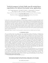
SL (n) 100 nm<br />
Contact<br />
Al 0.2 <strong>Ga</strong><strong>Sb</strong> 100 nm<br />
Barrier<br />
SL nid 2.4 µm<br />
Absorber<br />
SL (n) 360 nm<br />
Contact<br />
Al 0.2 <strong>Ga</strong><strong>Sb</strong> 100 nm<br />
Etch stop layer<br />
<strong>Ga</strong><strong>Sb</strong>:Te 2”<br />
Substrate<br />
Figure 3. Heterostructure schematic of <strong><strong>In</strong>As</strong>/<strong>Ga</strong><strong>Sb</strong> SLs MWIR detector<br />
Each processed FPA die consists of 320 x 256 pixels with a 30 µm pitch. Processing was initiated by defining<br />
24 µm x 24 µm squares with standard UV photolithography and a shallow wet chemical etch <strong>using</strong> phosphoric acid was<br />
performed. It is to be noted that the depth of the shallow etch was equal to 0.15 nm, which corresponds to the middle of<br />
the barrier layer. Thus the active absorber layer underneath is untouched. Then an inductively coupled plasma (ICP) dry<br />
etch to the middle of the bottom contact layer on the three outermost rows and columns of the FPA was undertaken. A<br />
scanning electron microscope (SEM) image of a part of a fully processed FPA is shown in Figure 4 and illustrates the<br />
two steps of the etching process. Top and bottom contacts were then deposited <strong>using</strong> an electron beam metal evaporation<br />
system. We used Ti\Pt\Au (500Å\500Å\3000Å) as contact metals for both top and bottom ohmic contact metallization.<br />
Finally, to enable well defined <strong>In</strong>dium bumps, an under bump metal (UBM) deposition was conducted <strong>using</strong> Ti\Ni\Au<br />
(300Å\1500Å\500Å). <strong>In</strong>dium bumps with a thickness ~3 µm were thermally evaporated on the UBM metal pads.<br />
Following this, the FPAs were hybridized to ISC0209 read-out integrated circuits (ROICs) made by <strong>In</strong>digo.<br />
To reduce the free carrier absorption in the substrate and to minimize the thermal stress between the FPA and<br />
the ROIC under cool-down conditions, the backside of the FPAs were thinned by a combination of mechanical polishing<br />
and wet chemical etching. Hybridization and characterization of the FPAs were undertaken at QmagiQ, LLC. Hybrid<br />
FPAs were tested with a CamIRa <strong>infrared</strong> FPA evaluation system made by SE-IR Corp. with a Ge window for the<br />
imaging performance tests. For the tests, the background was a 300K scene under f/4 illumination. The applied bias was<br />
equal to 0.7V and is defined as a positive voltage applied to the bottom contact of the FPA.<br />
The noise equivalent temperature difference (NETD) was measured by acquiring a sequence of 25 image scans<br />
with the focal plane exposed to a uniform blackbody target at 30°C and extracting the temporal noise for each pixel. A<br />
histogram of the NETD distribution is shown in Figure 5 (a) for an integration time of 16.3 ms. Good spatial uniformity<br />
is obtained over the array, resulting in a median NETD value of 23.8 mK with a standard deviation of 10 mK at a FPA<br />
temperature of 77K. Pixel operability was equal to 79% with predominant single pixel faults without large clusters.<br />
Pixel outages probably originated from the weak connection between the ROIC and FPA since the thickness of indium<br />
bumps was equal only 3 µm and no reflow process was utilized.<br />
Proc. of SPIE Vol. 6940 69400E-4