W1683 Manual - Grizzly Industrial Inc.
W1683 Manual - Grizzly Industrial Inc.
W1683 Manual - Grizzly Industrial Inc.

You also want an ePaper? Increase the reach of your titles
YUMPU automatically turns print PDFs into web optimized ePapers that Google loves.
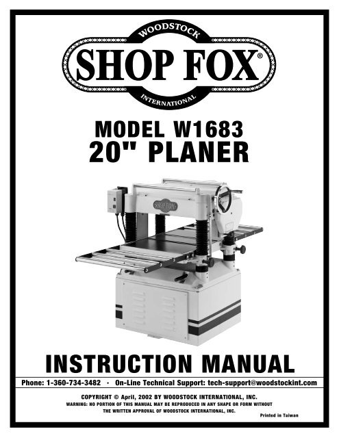
MODEL <strong>W1683</strong><br />
20" PLANER<br />
INSTRUCTION MANUAL<br />
Phone: 1-360-734-3482 • On-Line Technical Support: tech-support@woodstockint.com<br />
COPYRIGHT © April, 2002 BY WOODSTOCK INTERNATIONAL, INC.<br />
WARNING: NO PORTION OF THIS MANUAL MAY BE REPRODUCED IN ANY SHAPE OR FORM WITHOUT<br />
THE WRITTEN APPROVAL OF WOODSTOCK INTERNATIONAL, INC.<br />
Printed in Taiwan
WARNING<br />
Some dust created by power sanding, sawing,<br />
grinding, drilling, and other construction activities<br />
contains chemicals known to the State of California<br />
to cause cancer, birth defects or other reproductive<br />
harm. Some examples of these chemicals are:<br />
• Lead from lead-based paints.<br />
• Crystalline silica from bricks, cement, and<br />
other masonry products.<br />
• Arsenic and chromium from chemically<br />
treated lumber.<br />
Your risk from these exposures varies, depending on<br />
how often you do this type of work. To reduce your<br />
exposure to these chemicals: work in a well<br />
ventilated area, and work with approved safety<br />
equipment, such as those dust masks that are<br />
specially designed to filter out microscopic<br />
particles.
Table Of Contents<br />
PAGE<br />
1. INTRODUCTION ........................................................................................................2<br />
ABOUT YOUR NEW PLANER ....................................................................................2<br />
WOODSTOCK SERVICE AND SUPPORT ........................................................................2<br />
WARRANTY AND RETURNS ......................................................................................3<br />
PLANER MACHINE SPECIFICATIONS............................................................................3<br />
2. SAFETY FIRST! ..........................................................................................................4<br />
SAFETY INSTRUCTIONS........................................................................................4-5<br />
ADDITIONAL SAFETY INSTRUCTIONS FOR PLANERS........................................................6<br />
ELECTRICAL REQUIREMENTS....................................................................................7<br />
220V OPERATION ................................................................................................7<br />
EXTENSION CORDS................................................................................................7<br />
GROUNDING ........................................................................................................7<br />
3. ASSEMBLY................................................................................................................8<br />
BOX CONTENTS....................................................................................................8<br />
OVERVIEW ..........................................................................................................8<br />
SHOP PREPARATION..............................................................................................9<br />
CLEANING MACHINE ..............................................................................................9<br />
EXTENSION ROLLERS ..........................................................................................10<br />
HANDWHEEL ....................................................................................................11<br />
DUST HOOD ......................................................................................................11<br />
SWITCH............................................................................................................12<br />
KNIFE SETTING JIG..............................................................................................12<br />
4. ADJUSTMENTS ........................................................................................................13<br />
LOCATION OF CONTROLS......................................................................................13<br />
MOVING BED ROLLERS..........................................................................................14<br />
TABLE ........................................................................................................14-16<br />
CHECKING KNIVES ..............................................................................................17<br />
KNIFE ADJUSTMENT ........................................................................................18-19<br />
FEED ROLLERS, CHIPBREAKER & PRESSURE BAR ....................................................20-21<br />
CHIP DEFLECTOR ................................................................................................22<br />
ANTI-KICKBACK PAWLS ........................................................................................22<br />
CHAIN TENSIONER ..............................................................................................23<br />
SPRING TENSION ................................................................................................23<br />
TABLE ROLLERS ................................................................................................24<br />
5. OPERATIONS ..........................................................................................................25<br />
TEST RUN ........................................................................................................25<br />
FEED RATE........................................................................................................25<br />
OPERATIONAL TIPS ............................................................................................26<br />
TROUBLESHOOTING PLANING RESULTS ....................................................................27<br />
AFTERMARKET SETUP ACCESSORIES ........................................................................28<br />
6. MAINTENANCE ........................................................................................................29<br />
GENERAL ..........................................................................................................29<br />
CLEANING ........................................................................................................29<br />
TABLE AND BASE ................................................................................................29<br />
LUBRICATION ....................................................................................................30<br />
BELT TENSION ..................................................................................................31<br />
PULLEY ALIGNMENT ............................................................................................31<br />
WIRING DIAGRAM ....................................................................................................32<br />
TROUBLESHOOTING ..................................................................................................33<br />
7. CLOSURE ..............................................................................................................34<br />
DIAGRAMS AND PARTS LISTS..............................................................................35-42<br />
WARRANTY AND REPLACEMENT..............................................................................43<br />
INTRODUCTION<br />
USE THE QUICK GUIDE PAGE LABELS TO SEARCH OUT INFORMATION FAST!
INTRODUCTION<br />
INTRODUCTION<br />
ABOUT YOUR NEW PLANER<br />
This new Shop Fox ® 20" Planer has been specially designed to provide many years of trouble free service.<br />
Close attention to detail, ruggedly built parts and a rigid quality control program assure safe and reliable<br />
operation.<br />
Woodstock International, <strong>Inc</strong>. is committed to customer satisfaction in providing this manual. It is our<br />
intent to make sure all the information necessary for safety, ease of assembly, practical use and<br />
durability of this product be included.<br />
If you should have any comments regarding this manual, please contact us at:<br />
Woodstock International, <strong>Inc</strong>.<br />
P.O. Box 2309<br />
Bellingham, WA 98227<br />
WOODSTOCK SERVICE AND SUPPORT<br />
We stand behind our machines! In the event that a defect is found, parts are missing or questions arise<br />
about your machine, please contact Woodstock International Service and Support at 1-360-734-3482 or<br />
tech-support@woodstockint.com. Our knowledgeable staff will help you troubleshoot problems, send out<br />
parts or arrange warranty repair or returns.<br />
2
WARRANTY AND RETURNS<br />
Woodstock International, <strong>Inc</strong>. warrants all SHOP FOX ® machinery to be free of defects from workmanship<br />
and materials for a period of 2 years from the date of original purchase by the original owner. This<br />
warranty does not apply to defects due directly or indirectly to misuse, abuse, negligence or accidents,<br />
lack of maintenance, or to repair or alterations made or specifically authorized by anyone other than<br />
Woodstock International, <strong>Inc</strong>.<br />
INTRODUCTION<br />
Woodstock International, <strong>Inc</strong>. will repair or replace, at its expense and at its option, the SHOP FOX ®<br />
machine or machine part which in normal use has proven to be defective, provided that the original<br />
owner returns the product prepaid to the SHOP FOX ® factory service center or authorized repair facility<br />
designated by our Bellingham, WA office, with proof of their purchase of the product within 2 years, and<br />
provides Woodstock International, <strong>Inc</strong>. reasonable opportunity to verify the alleged defect through<br />
inspection. If it is determined there is no defect, or that the defect resulted from causes not within the<br />
scope of Woodstock International <strong>Inc</strong>.'s warranty, then the original owner must bear the cost of storing<br />
and returning the product.<br />
This is Woodstock International, <strong>Inc</strong>.'s sole written warranty and any and all warranties that may be<br />
implied by law, including any merchantability or fitness, for any particular purpose, are hereby limited<br />
to the duration of this written warranty. We do not warrant that SHOP FOX ® machinery complies with<br />
the provisions of any law or acts. In no event shall Woodstock International, <strong>Inc</strong>.'s liability under this<br />
warranty exceed the purchase price paid for the product, and any legal actions brought against<br />
Woodstock International, <strong>Inc</strong>. shall be tried in the State of Washington, County of Whatcom. We shall in<br />
no event be liable for death, injuries to persons or property or for incidental, contingent, special or<br />
consequential damages arising from the use of our products.<br />
Every effort has been made to ensure that all SHOP FOX ® machinery meets high quality and durability<br />
standards. We reserve the right to change specifications at any time because of our commitment to<br />
continuously improve the quality of our products.<br />
Planer Machine Specifications<br />
Motor ..................................................................5 H.P., 220V, Single-Phase<br />
Amps ................................................................................................28<br />
Cutting Width ....................................................................................20"<br />
Cutting Height ....................................................................................8"<br />
Minimum Stock Thickness ...................................................................... 1 ⁄4"<br />
Minimum Stock Length ............................................................................7"<br />
Maximum Depth of Cut .......................................................................... 1 ⁄8"<br />
Cutterhead Diameter ..........................................................................3 3 ⁄16"<br />
Cutterhead Speed ....................................................................5500 R.P.M.<br />
Table Size ..............................................................................25 3 ⁄4" x 20"<br />
Knives ........................................................................................4 H.S.S.<br />
Feed Rates ..........................................................................18 & 23 F.P.M.<br />
3
SAFETY FIRST!<br />
SAFETY<br />
READ MANUAL BEFORE OPERATING MACHINE<br />
FAILURE TO FOLLOW INSTRUCTIONS BELOW WILL<br />
RESULT IN PERSONAL INJURY<br />
Indicates an imminently hazardous situation which, if not avoided, WILL<br />
result in death or serious injury.<br />
Indicates a potentially hazardous situation which, if not avoided, COULD<br />
result in death or serious injury.<br />
Indicates a potentially hazardous situation which, if not avoided, MAY<br />
result in minor or moderate injury. It may also be used to alert against<br />
unsafe practices.<br />
NOTICE<br />
This symbol is used to alert the user to useful information about proper<br />
operation of the equipment.<br />
1. Thoroughly read the instruction manual before operating your machine. Learn the applications,<br />
limitations and potential hazards of this machine. Keep manual in a safe, convenient place for future<br />
reference.<br />
2. Keep work area clean and well lighted. Clutter and inadequate lighting invite potential hazards.<br />
3. Ground all tools. If a machine is equipped with a three-prong plug, it must be plugged into a threehole<br />
electrical outlet or grounded extension cord. If using an adapter to aid in accommodating a twohole<br />
receptacle, ground using a screw to a known ground.<br />
4. Wear eye protection at all times. Use safety glasses with side shields or safety goggles (that meet<br />
the national safety standards) while operating this machine.<br />
5. Avoid dangerous environments. Do not operate this machine in wet or open flame environments.<br />
Airborne dust particles could cause an explosion and severe fire hazard.<br />
6. Ensure all guards are securely in place and in working condition.<br />
7. Make sure switch is in the “OFF” position before connecting power to machine.<br />
8. Keep work area clean and free of clutter, grease, etc.<br />
9. Keep children and visitors away. All visitors should be kept a safe distance away while operating<br />
unit.<br />
10. Childproof workshop with padlocks, master switches or by removing switch keys.<br />
11. Disconnect machine when cleaning, adjusting or servicing.<br />
12. Do not force tool. The machine will do a safer and better job at the rate for which it was designed.<br />
4
13. Use correct tool. Do not force machine or attachment to do a job for which it was not designed.<br />
14. Wear proper apparel. Do not wear loose clothing, neck ties, gloves, jewelry, etc.<br />
15. Remove adjusting keys and wrenches before turning the machine on. Make this a habit!<br />
16. Use proper extension cord. When using an extension cord, make sure it is in good condition. Use<br />
extension cords 100' or less in length that are rated Hard Service (grade S) or better, and that have<br />
a conductor size of 16 A.W.G. A drop in line voltage, loss of power and overheating can result when<br />
using an undersized cord. The extension cord must have a ground wire and ground plug pin, as well.<br />
17. Keep proper footing and balance at all times.<br />
SAFETY<br />
18. Do not leave machine unattended—wait until it comes to a complete stop before leaving the area.<br />
19. Perform machine maintenance and care. Follow lubrication and accessory attachment instructions<br />
in the manual.<br />
20. Keep machine away from open flame. Operating machines near pilot lights and/or open flames<br />
creates a high risk if dust is dispersed in the area. Dust particles and an ignition source may cause<br />
an explosion. Do not operate the machine in high risk areas, including but not limited to, those<br />
mentioned above.<br />
21. Do not use machine under the influence of drugs or alcohol or if you are excessively tired.<br />
22. Do not let untrained people use the machine if they are not supervised by an experienced<br />
operator.<br />
23. If at any time you are experiencing difficulties performing the intended operation, stop using the<br />
machine! Then contact our service department or ask a qualified expert how the operation should<br />
be performed.<br />
24. Mag switches can be accidentally turned on when they are bumped. Always be aware of the mag<br />
switch location when moving items around the shop.<br />
Operating this equipment has the potential<br />
for flying debris to cause eye injury. Always<br />
wear safety glasses or goggles when<br />
operating equipment. Everyday glasses or<br />
reading glasses only have impact resistant<br />
lenses, they are not safety glasses. Be<br />
certain the safety glasses you wear meet<br />
the appropriate standards of the American<br />
National Standards Institute (ANSI).<br />
5
ADDITIONAL SAFETY INSTRUCTIONS FOR PLANERS<br />
1. Always make sure the planer is on firm ground and is stable before operating. Immediately fix or<br />
shim the planer if it rocks or wobbles.<br />
SAFETY<br />
2. Always inspect the workpiece before running it through the planer. Stock with loose knots, nails,<br />
staples, dirt or other foreign objects should be rejected from use or corrected by eliminating the<br />
condition that makes it questionable.<br />
3. Always make sure that all components of the planer are adjusted to their proper specifications<br />
before planing stock.<br />
4. Always use the help of another person or some type of support fixture when planing long stock.<br />
5. Never stand behind the workpiece when you are feeding it into the planer; the workpiece could<br />
possibly kick back and be thrown in the direction from which it came.<br />
6. Never operate the planer if knives are dull or damaged. Sharp knives are safer and produce better<br />
final results.<br />
7. Never process any material through the planer other than wood. This planer is designed for wood<br />
only!<br />
8. Always take multiple light cuts rather than excessively deep cuts.<br />
9. Never attempt to free a stalled workpiece while the planer is powered on and plugged in.<br />
10. Absolutely never reach inside the planer or open the top cover while the planer is powered on<br />
and/or plugged in.<br />
11. Never plane wood that is less than 7" long or less than 1 ⁄4" thick.<br />
12. Always wear hearing protection when operating the planer.<br />
Read the manual<br />
completely before<br />
assembly and operation.<br />
Become familiar with the<br />
machine and its operation<br />
before beginning any<br />
work. Serious personal<br />
injury may result if safety<br />
or operational information<br />
is not understood or<br />
followed.<br />
No list of safety guidelines can be<br />
complete. Every shop environment is<br />
different. Always consider safety first, as it<br />
applies to your individual working<br />
conditions. Use this and other machinery<br />
with caution and respect. Failure to do so<br />
could result in serious personal injury,<br />
damage to equipment or poor work results.<br />
6
ELECTRICAL REQUIREMENTS<br />
NOTICE<br />
NEVER replace the circuit breaker with one<br />
rated at a higher amperage or damage to the<br />
circuit may occur.<br />
This equipment must be<br />
grounded. Verify that any<br />
existing electrical outlet and<br />
circuit you intend to plug<br />
into is actually grounded.<br />
Under no circumstances<br />
should the grounding pin<br />
from any three-pronged plug<br />
be removed. Serious injury<br />
may occur.<br />
Figure 1. Typical 220V 3-prong plug and outlet.<br />
220V Operation<br />
The motor supplied with your new planer is<br />
rated at 5 H.P. and will draw approximately 28<br />
amps during 220 volt operation. When choosing<br />
an outlet for this machine, we recommend<br />
using a NEMA L6-30A with a 30 amp circuit<br />
breaker or fuse. Keep in mind that a circuit<br />
being used by other machines or tools at the<br />
same time will add to the total load being<br />
applied to the circuit. Add up the load ratings<br />
of all machines on the circuit. If this number<br />
exceeds the rating of the circuit breaker, fuse<br />
or wires, use a different circuit.<br />
Extension Cords<br />
We do not recommend using an extension cord<br />
for 220V equipment. Instead, arrange the<br />
placement of your machinery and installed<br />
wiring to eliminate the need for extension<br />
cords. If you must use an extension cord, make<br />
sure it is rated Hard Service (grade S) and<br />
capable of handling a 28 amp load. The<br />
extension cord must always contain a ground<br />
wire and plug pin. Be sure to ask an expert<br />
about the correct gauge to use with your<br />
desired cord length. Always repair or replace<br />
extension cords when they become worn or<br />
damaged.<br />
Grounding<br />
This machine must be grounded! See Figure 1.<br />
The electrical cord supplied with the Model<br />
<strong>W1683</strong> does not come with a 220 volt plug. Use<br />
a plug with a ground pin. If your outlet does not<br />
accommodate a ground pin, have it replaced by<br />
a qualified electrician or have an appropriate<br />
adapter installed and grounded properly. An<br />
adapter with a grounding wire does not<br />
guarantee the machine will be grounded. A<br />
ground source must be verified.<br />
SAFETY<br />
7
ASSEMBLY<br />
ASSEMBLY<br />
The following is a description of the components<br />
shipped with the Shop Fox ® <strong>W1683</strong> 20" Planer.<br />
Should any parts be missing, examine the<br />
packaging carefully to be sure parts are not<br />
among the packing materials. If any key parts<br />
are missing, contact Woodstock International,<br />
<strong>Inc</strong>. at 360-734-3482 or by e-mail at:<br />
tech-support@woodstockint.com.<br />
Box Contents<br />
1. Planer Unit<br />
2. Dust Hood<br />
3. Starter Switch<br />
4. Rollers (2)<br />
5. Handwheel<br />
6. Hardware Bag:<br />
(6) M6-1.0 x 12 Hex Bolts<br />
(6) 6mm Flat Washers<br />
(8) 1 ⁄2" Flat Washers<br />
(8) M10-1.5 x 25 Hex Bolts<br />
(1) Knife Setting Rod<br />
(2) Knife Setting Gauge<br />
(4) 9mm E-Clip Ring<br />
(1) Handle<br />
(1) 3mm Allen Wrench<br />
(1) 4mm Allen Wrench<br />
(1) 5mm Allen Wrench<br />
(1) 6mm Allen Wrench<br />
(1) 8mm & 10mm Combo Wrench<br />
(1) 12mm & 14mm Combo Wrench<br />
(1) 17mm & 19mm Combo Wrench<br />
Overview<br />
We have assembled most of your new planer for<br />
you at the factory; however, the parts shown in<br />
Figure 2 still need to be assembled after<br />
delivery. Please take your time and try to be as<br />
accurate as possible when following each step.<br />
This care will provide you with better results<br />
when you are finished.<br />
Additional Tools Required: Besides the tools<br />
that were included with the planer, you will also<br />
need a Phillips ® screwdriver, a flat-head<br />
screwdriver and a good straightedge. A set of<br />
feeler gauges and a dial indicator will also be<br />
necessary for the Adjustments section.<br />
Figure 2. Parts that need to be assembled.<br />
Do not connect the<br />
machine to power at this<br />
time. The machine must<br />
remain unplugged<br />
throughout the entire<br />
assembly process. Failure<br />
to do this may result in<br />
serious personal injury.<br />
8
Shop Preparation<br />
• Floor Load: Your Model <strong>W1683</strong> represents a<br />
large weight load in a small footprint. Most<br />
commercial floors are suitable for the<br />
planer. Some residential floors may require<br />
additional bracing to support both machine<br />
and operator.<br />
• Working Clearances: Consider existing and<br />
anticipated needs, size of material to be<br />
processed through each machine, and space<br />
for auxiliary stands, work tables or other<br />
machinery when establishing a location for<br />
your planer.<br />
• Lighting and Outlets: Lighting should be<br />
bright enough to eliminate shadow and<br />
prevent eye strain. Electrical circuits should<br />
be dedicated or large enough to handle<br />
amperage requirements. Outlets should be<br />
located near each machine so power or<br />
extension cords are clear of high-traffic<br />
areas. Observe local electrical codes for<br />
proper installation of new lighting, outlets,<br />
or circuits.<br />
Cleaning Machine<br />
The table and other unpainted parts of the<br />
Model <strong>W1683</strong> are coated with a waxy grease that<br />
protects them from corrosion during shipment.<br />
Clean this grease off with a solvent cleaner or<br />
citrus-based degreaser. Do not use chlorinebased<br />
solvents—if you happen to splash some<br />
onto a painted surface, you will ruin the finish.<br />
Do not use gasoline or<br />
other petroleum-based<br />
solvents. They have low<br />
flash points which make<br />
them extremely<br />
flammable. A risk of<br />
explosion and burning<br />
exists if these products<br />
are used. Serious personal<br />
injury may occur if this<br />
warning is ignored.<br />
ASSEMBLY<br />
The Model <strong>W1683</strong> is a<br />
heavy machine, 840 lbs.<br />
shipping weight. Use<br />
power equipment.<br />
Serious personal injury<br />
may occur if safe moving<br />
methods are not<br />
followed.<br />
Make your shop “child<br />
safe.” Ensure that your<br />
workplace is inaccessible<br />
to youngsters by closing<br />
and locking all entrances<br />
when you are away. Never<br />
allow visitors in your shop<br />
when assembling,<br />
adjusting or operating<br />
equipment.<br />
Do not smoke while using<br />
solvents. A risk of<br />
explosion or fire exists and<br />
may result in serious<br />
personal injury.<br />
Many of the solvents<br />
commonly used to clean<br />
machinery can be toxic<br />
when inhaled or<br />
ingested. Always work in<br />
well-ventilated areas far<br />
from potential ignition<br />
sources when dealing<br />
with solvents. Use care<br />
when disposing of waste<br />
rags and towels to be<br />
sure they do not create<br />
fire or environmental<br />
hazards.<br />
9
Extension Rollers<br />
The extension roller assemblies are identical for<br />
both the infeed and the outfeed ends of the<br />
table. To mount these assemblies:<br />
1. Attach an extension bar to the end of each<br />
roller. Secure these in place with the 12mm<br />
snap rings provided in the hardware bag.<br />
ASSEMBLY<br />
2. Match the tapped holes on the side of the<br />
table to the extension bars. Lightly secure in<br />
place with the M10-1.5 x 25 hex bolts and<br />
washers from the hardware bag.<br />
3. The end (outside) roller is fixed in place.<br />
Place a straightedge flat across the table<br />
and across the rollers as shown in Figure 3.<br />
Adjust the end roller so it is flush with the<br />
table, and tighten the M10-1.5 x 25 hex<br />
bolts to secure the extension bars in place.<br />
Figure 3. Checking roller extension with a<br />
straightedge.<br />
4. The two inside rollers are mounted in<br />
slotted holes so they can be adjusted flush<br />
with the table and the end roller. Make<br />
these adjustments and tighten the bolts to<br />
secure the inside rollers in place.<br />
The top of the rollers should now be completely<br />
even with the top of the table. Double-check to<br />
make sure that the rollers did not move during<br />
the tightening process.<br />
10
Handwheel<br />
Figure 4. Handwheel attached correctly.<br />
The handwheel operates the chain driven system<br />
that raises/lowers the table to control the<br />
cutting depth.<br />
To mount the handwheel:<br />
1. Secure the handwheel to the worm gear<br />
shaft (as shown in Figure 4) with the hex<br />
nut and washer that is already on the<br />
threads.<br />
2. Thread the handle into the handwheel and<br />
tighten the hex nut to keep it locked in<br />
place.<br />
Dust Hood<br />
ASSEMBLY<br />
Figure 5. Dust hood attached to planer.<br />
The dust hood included should only be installed<br />
if you plan on hooking your planer up to a dust<br />
collection system.<br />
To install the dust hood:<br />
1. Match the holes in the dust hood to the<br />
tapped holes in the planer casting on the<br />
outfeed end.<br />
2. Secure the dust hood with the (6) M6-1.0 x<br />
12 hex bolts from the hardware bag, as<br />
shown in Figure 5.<br />
3. Attach a 5" dust hose to the dust port.<br />
11
Switch<br />
ASSEMBLY<br />
The prewired magnetic switch needs to be<br />
mounted to the planer head casting.<br />
To mount the switch:<br />
1. Match the holes at the back of the switch<br />
with the tapped holes in the front, lefthand<br />
corner of the planer.<br />
2. Secure the switch to the head casting with<br />
the cap screws as shown in Figure 6.<br />
3. Read Section 2: Circuit Requirements in this<br />
manual, then install an appropriate plug to<br />
the power wire.<br />
Figure 6. Attaching switch to the planer.<br />
DO NOT connect machine<br />
to the power at this time!<br />
Wait until all other<br />
assembly instructions and<br />
adjustments have been<br />
completed.<br />
Knife Setting Jig<br />
We have provided a jig to make the knife setting<br />
process easy and quick. Please refer to Figure 7<br />
for jig component identification while<br />
assembling.<br />
To assemble the knife setting jig:<br />
1. Snap one of the E-clips over the notch on<br />
one end of the knife setting rod.<br />
2. Slide the aluminum knife setting jig<br />
brackets onto the rod.<br />
3. Snap the other E-clip on the other end of<br />
the knife setting rod.<br />
Refer to page 17 for use.<br />
Figure 7. Knife setting jig.<br />
12
ADJUSTMENTS<br />
Do not connect power to<br />
the machine while<br />
performing adjustments.<br />
Failure to follow this<br />
warning may result in<br />
serious personal injury.<br />
Planer knives are<br />
dangerously sharp! Use<br />
extreme caution when<br />
working near cutting<br />
surfaces. Failure to<br />
exercise care while<br />
working near knives could<br />
result in severe injury.<br />
Location of Controls<br />
Take the time to familiarize yourself with the<br />
controls of your new planer. They will be<br />
frequently mentioned throughout the<br />
instructions in this manual, and the better you<br />
know your machine, the better you can make it<br />
perform. Figure 8 points out the key controls<br />
and their locations.<br />
As with all precision machinery, adjustments to<br />
the planer require very close tolerances. The<br />
adjustments described in this section will be<br />
factory set. However, during the life of the<br />
machine it will necessary to make these<br />
adjustments yourself. Many of these<br />
adjustments require the use of an indicating tool<br />
such as a dial indicator or a Rotacator ® to<br />
achieve accurate results.<br />
Table Height<br />
Handwheel<br />
ADJUSTMENTS<br />
ON/OFF<br />
Switch<br />
Table Height<br />
Scale<br />
Feed Rate<br />
Control<br />
Table Height<br />
Lock Knobs<br />
Table Extension Rollers<br />
Figure 8. Machine controls.<br />
13
Moving Bed Rollers<br />
In order to perform table adjustments, the bed<br />
rollers must be adjusted below the surface of<br />
the table.<br />
To move the bed rollers:<br />
1. Loosen the setscrews where the bed rollers<br />
mount to the planer body (on both ends) as<br />
shown in Figure 9.<br />
2. Use a wrench to lower the rollers on their<br />
eccentric shafts.<br />
Leave the bed rollers in this position until<br />
instructed to adjust them at the end of this<br />
section.<br />
Figure 9. Bed roller setscrews.<br />
ADJUSTMENTS<br />
Table<br />
The most critical adjustments made on your new<br />
planer are dependent on the table being<br />
parallel to the cutterhead body. Because of this<br />
relationship, checking the table is the first step<br />
to setting up an accurate planer.<br />
There are two movements you should be<br />
concerned about when checking/adjusting the<br />
table—the table should be parallel to the head<br />
casting from front-to-back, and the table should<br />
be parallel with the cutterhead body from sideto-side.<br />
Side View<br />
Front View<br />
Figure 10. Gauge block.<br />
The table has been pre-set at the factory, but it<br />
is a good idea to check any machine thoroughly<br />
before use.<br />
To check the table:<br />
1. Make sure machine is unplugged!<br />
2. Make the gauge shown in Figure 10 out of a<br />
block of wood.<br />
14
3. Place the block on one end of the table,<br />
directly under the cutterhead body. Raise<br />
the table up so the block only touches the<br />
cutterhead body (keep knives rotated out of<br />
the way for this step).<br />
4. Without moving the table, slide the block of<br />
wood to the other end of the cutterhead. If<br />
the block of wood will not fit, or if the block<br />
is below the cutterhead body, measure this<br />
gap with a feeler gauge. If the difference is<br />
more than .002", then the table needs to be<br />
adjusted from left to right.<br />
Figure 11. Checking table/head casting in front.<br />
5. Place the block under the middle-front of<br />
the head casting. Raise the table up so the<br />
block barely touches the head casting as<br />
shown in Figure 11.<br />
6. Remove the block and place it between the<br />
middle-rear of the head casting and the<br />
table. If there is a gap or it will not fit under<br />
the head casting, measure the difference<br />
with a feeler gauge. If this measurement is<br />
more than .002", then the table needs to be<br />
adjusted from front to back.<br />
7. There are two methods to adjust the table<br />
on the Model <strong>W1683</strong>. The first is for<br />
adjustments smaller than .016" and the<br />
second is for adjustments larger than .016".<br />
ADJUSTMENTS<br />
To adjust the table less than .016":<br />
Figure 12. Table mounting screws.<br />
1. Use the table mounting screws shown in<br />
Figure 12. Loosen the screws and lift/lower<br />
the table until the table and the cutterhead<br />
body are parallel with each other and the<br />
table is parallel with the head casting from<br />
front to back. This may require some trial<br />
and error.<br />
2. Adjust each column on both sides until the<br />
table is properly set. While adjusting the<br />
columns, tighten each screw after each step<br />
to ensure accurate results.<br />
15
To adjust the table more than .016":<br />
1. Remove the front cabinet cover.<br />
2. On the underside of the table there is a<br />
chain drive and five sprockets as shown in<br />
Figure 13. The four sprockets in the corners<br />
control the movement of the table columns.<br />
The fifth sprocket is the idler sprocket that<br />
controls the chain tension. Loosen the two<br />
bolts on the idler sprocket bracket (as<br />
shown in Figure 13) to loosen the chain so<br />
that each sprocket can be rotated on its<br />
own. Make sure to hold the chain away from<br />
the sprocket while you adjust it.<br />
Idler Sprocket Bracket<br />
Figure 13. Underside of table.<br />
ADJUSTMENTS<br />
3. Moving the sprockets clockwise lowers the<br />
table and moving them counter-clockwise<br />
raises the table. Each tooth on the corner<br />
sprockets equals .016" of vertical movement<br />
when the cogs are turned (see illustration in<br />
Figure 14). Make sure, as you adjust each<br />
sprocket, that you count the number of<br />
teeth that pass a fixed point.<br />
Knowing how far you turned one sprocket<br />
will help you keep the other side consistent<br />
if you are adjusting two columns together.<br />
4. After you have the table adjusted to within<br />
.016" from front-to-back and from side-toside,<br />
tighten the chain so all of the slack is<br />
removed.<br />
5. Now follow the previous instructions for<br />
adjusting the table when it is less than .016"<br />
from its proper position.<br />
Sprocket<br />
Figure 14. Understanding sprocket movement.<br />
Do not connect power to<br />
the machine while<br />
performing adjustments.<br />
Failure to follow this<br />
warning may result in<br />
serious personal injury.<br />
16
Checking Knives<br />
The Model <strong>W1683</strong> features a 4 knife cutterhead.<br />
These knives must be checked and adjusted<br />
after regular use. Adjusting the knives is also an<br />
important part of the maintenance process.<br />
Correctly positioned knives act as a reference<br />
point for adjusting the feed rollers, the chip<br />
breaker and the pressure bar.<br />
Figure 15. Cover removed from planer.<br />
These Points Must<br />
All Touch Evenly<br />
Figure 16. Correct jig position on cutterhead.<br />
When checking/adjusting the knives, keep in<br />
mind that the knife edge should be as precise as<br />
possible at tolerances within .002" from one end<br />
to the other. Improperly adjusted knives may<br />
unbalance the cutterhead, reduce the sharpness<br />
of knife edges prematurely, shorten bearing<br />
life, and produce poor planing results.<br />
To check the knives:<br />
1. Remove the upper cover as shown in Figure<br />
15 so you have access to the top of the<br />
cutterhead.<br />
2. Remove the V-belt cover from the left-hand<br />
side of the planer (facing front).<br />
3. Using the V-belt to rotate the cutterhead,<br />
turn the cutterhead so one of the knives is<br />
accessible.<br />
4. Place the knife setting jig on the<br />
cutterhead. Both feet should sit solidly on<br />
the cutterhead and the knife should barely<br />
touch the center of the jig as shown in<br />
Figure 16.<br />
5. If the knife does not contact the center of<br />
the jig, or if the knife contacts the center of<br />
the jig but both feet will not sit solidly on<br />
the cutterhead, then the knives will need to<br />
be adjusted.<br />
ADJUSTMENTS<br />
For quick and easy knife setup, consider<br />
purchasing a Planer Pal ® . This handy tool allows<br />
you to quickly set the knives to within .001" from<br />
one end to the other. See “Aftermarket<br />
Accessories” at the end of the Operations<br />
section for more details.<br />
17
Knife Adjustment<br />
The Model <strong>W1683</strong> is equipped with both springs<br />
and jack screws for knife adjustment. These two<br />
options have been provided for operator<br />
preference. Both types have advantages and<br />
disadvantages. Springs allow adjustments to be<br />
made quickly, while jack screws are more<br />
accurate. The following instructions offer<br />
suggestions for both methods, followed by the<br />
procedures for tightening the gib bolts.<br />
ADJUSTMENTS<br />
Springs under the knives exert upward pressure<br />
while wedge-type gibs and gib bolts lock the<br />
knives in place. See Figure 17 for cutterhead<br />
assembly identification.<br />
To adjust the knives using the springs:<br />
1. Unplug the machine from the power<br />
source!<br />
2. Lower the jack screws completely to get<br />
them out of the way. Loosen the gib bolts so<br />
the knife will move upward from the<br />
pressure of the springs.<br />
3. Place the knife setting jig on the cutterhead<br />
so both feet sit solidly on the cutterhead<br />
and so that the center of the jig pushes<br />
down on the knife (similar to Figure 16).<br />
Make sure equal pressure is placed on both<br />
ends of the jig and that the jig is parallel<br />
with the cutterhead.<br />
4. Tighten the knives by following “tightening”<br />
instructions on the next page.<br />
Figure 17. Understanding cutterhead assembly.<br />
Jack Screws support the knives from<br />
underneath. By threading the jack screws in or<br />
out, you can precisely control the knife height.<br />
To adjust the knives using the jack screws:<br />
1. Unplug the machine from the power<br />
source!<br />
2. Loosen the gib bolts and remove the gib and<br />
knives. Remove all of the springs and place<br />
them in a plastic bag. Tape the bag to the<br />
inside of the cabinet so they do not get lost.<br />
3. Place the knives, gibs, and gib bolts back in<br />
the cutterhead as they were before<br />
removal. Make sure the knives are resting on<br />
the jack screws when you install them.<br />
4. Place the knife setting jig on the cutterhead<br />
so both feet sit solidly on the body of the<br />
cutterhead. If the knife does not allow the<br />
jig to sit on the cutterhead evenly, raise or<br />
lower the knife with the jack screws to<br />
adjust as needed.<br />
5. Tighten the knives by following the<br />
“tightening” instructions on the next page.<br />
18
To tighten the knives after adjustment:<br />
Do not connect power to<br />
the machine while<br />
performing adjustments.<br />
Failure to follow this<br />
warning may result in<br />
serious personal injury.<br />
1. Snug the gib bolts on each end of the knife<br />
but do not completely tighten them. In this<br />
manner, work toward the center of the<br />
knife by alternating back-and-forth from<br />
each end of the knife. Figure 18 illustrates<br />
order of this sequence. Make sure you only<br />
snug the gib bolts enough to hold the knife<br />
in place. You will tighten them more later.<br />
1 3 5 6 4 2<br />
2. Rotate the cutterhead and repeat knife<br />
adjustments and step 1 tightening until you<br />
have performed these procedures on all of<br />
the knives.<br />
Figure 18. Gib bolt tightening sequence.<br />
Wear heavy leather gloves when tightening<br />
gib bolts in case the wrench slips off and your<br />
hand hits the knife. Planer knives are<br />
dangerously sharp. If care is not taken<br />
around them, serious injury may occur.<br />
NOTICE<br />
Uneven tightening of the gib bolts may cause<br />
the cutterhead to become unbalanced,<br />
which will lead to premature wear and tear<br />
of the knives.<br />
3. When you come back to the knife you<br />
started with, check the height with the jig<br />
to make sure that it is still correct. If the<br />
bolt height is not correct, fix as necessary<br />
and re-snug the gib bolts; if the height is<br />
correct, snug each bolt down a little more<br />
in the same alternating procedure you used<br />
before, but do not tighten the bolts<br />
completely. Repeat again with each knife.<br />
4. When you return to the original knife,<br />
tighten all gibs completely in the same<br />
fashion, repeating on all knives.<br />
ADJUSTMENTS<br />
19
Feed Rollers, Chip<br />
Breaker & Pressure<br />
Bar<br />
The feed rollers, the chip breaker and the<br />
pressure bar are factory set for general planing.<br />
If you need to alter the settings or reset them<br />
after maintenance, these components can be<br />
adjusted at the same time, assuming that the<br />
knife height is set correctly. The standard<br />
setting for the infeed roller, the chipbreaker<br />
and the pressure bar is .004"-.008" below the<br />
cutterhead knife at bottom dead center. The<br />
outfeed roller should be set to .020" below the<br />
cutterhead knife at bottom dead center.<br />
Figure 19. Board position on table.<br />
To adjust the feed rollers, the chip breaker<br />
and the pressure bar:<br />
ADJUSTMENTS<br />
1. Unplug the machine from the power<br />
source!<br />
2. You will need two boards that are the same<br />
height and are long enough to span the<br />
entire length of the table. An easy way to<br />
get two boards of the same height is to rip<br />
one board down the middle.<br />
3. Place each board across the entire length of<br />
the table, on each side of the table, similar<br />
to Figure 19.<br />
4. Rotate the cutterhead with the V-belt<br />
pulley so one of the knives is at bottom<br />
dead center. Bottom dead center is the<br />
furthest point down that the knife reaches<br />
in its rotation. The black line underneath<br />
the cutterhead in Figure 20 represents<br />
bottom dead center.<br />
Figure 20. Bottom dead center.<br />
5. Raise the table up until the boards barely<br />
touch the knife edge.<br />
6. Lower the feed rollers onto the boards with<br />
the adjustment controls shown in Figure<br />
21.<br />
Figure 21. Feed roller adjustment controls.<br />
20
7. Lower the chipbreaker and the pressure bar<br />
onto the boards, using the adjustment<br />
controls shown in Figures 22 and 23.<br />
8. Make sure that each of the adjustment<br />
controls for the feed rollers, the<br />
chipbreaker and the pressure bar are<br />
backed off enough so that they will allow<br />
the components to move below the current<br />
position on the board.<br />
Figure 22. Chipbreaker adjustment controls.<br />
9. To accurately perform this adjustment, you<br />
will need a dial indicator (not included).<br />
Place the dial indicator near the Shop Fox<br />
name plate that is directly above the table.<br />
Figure 23. Pressure bar adjustment controls.<br />
10. Position the indicator plunger on the table<br />
and lower the table .004"-.008". The feed<br />
rollers, the chipbreaker and the pressure<br />
bar should all move freely with the table. If<br />
they do not, make sure that they are all<br />
resting evenly on the boards at this current<br />
position.<br />
11. Lock the infeed roller, the chipbreaker and<br />
the pressure bar in place. They should now<br />
all be set between .004"-.008" below the<br />
knife edge when it is at bottom dead<br />
center.<br />
12. The outfeed roller should still be able to<br />
move with the table. Continue lowering the<br />
table another .012" (.008" + .012" =.020").<br />
The outfeed roller should now be set to<br />
approximately .020" below the knife edge at<br />
bottom dead center. Lock the outfeed roller<br />
in place.<br />
ADJUSTMENTS<br />
For super accurate setup, consider purchasing a<br />
Rotacator ® . This handy tool allows you to adjust<br />
the feed rollers, chipbreaker, and pressure bar<br />
to accuracy within .001" every time. See<br />
“Aftermarket Accessories” at the end of the<br />
Operations section for more details.<br />
21
Chip Deflector<br />
A chip deflector is mounted behind the<br />
cutterhead to keep wood chips from falling onto<br />
the outfeed roller.<br />
The power should not be<br />
connected to the planer<br />
at this time! If it is,<br />
serious injury may occur.<br />
To adjust the chip deflector:<br />
1. Loosen the chip deflector mounting bolts<br />
shown in Figure 24.<br />
2. Make sure the deflector is angled toward<br />
the cutterhead. Position the edge of the<br />
deflector to approximately 1 ⁄16" from the<br />
knife edge. Rotate the cutterhead with the<br />
V-belt pulley and make sure there is enough<br />
clearance between all the knives and the<br />
chip deflector.<br />
ADJUSTMENTS<br />
3. Re-tighten the mounting bolts and replace<br />
the top cover.<br />
Anti-Kickback Pawls<br />
The Model <strong>W1683</strong> features anti-kickback pawls<br />
(shown in Figure 25) as an important safety<br />
feature. These safety devices allow the<br />
workpiece to enter the planer without affecting<br />
the proper operation, but are designed to stop<br />
the workpiece from coming back out of the<br />
entrance in the event of a kickback.<br />
Figure 24. Chip deflector mounting bolts.<br />
NOTICE<br />
If you use a dust collector, move the chip<br />
deflector slightly farther away from the<br />
knives to help remove chips better.<br />
The anti-kickback pawls should be frequently<br />
checked to ensure that they swing free and<br />
easy. Do not try to lubricate the pawls.<br />
Lubrication may cause dust to build-up, which<br />
will restrict movement.<br />
Proper operation of the anti-kickback pawls<br />
is essential to the safe operation of the<br />
planer. If they aren’t working properly,<br />
they will not protect you if a kickback<br />
occurs.<br />
22<br />
Figure 25. Anti-kickback pawls.
The power should not be<br />
connected to the planer<br />
at this time! If it is,<br />
serious injury may occur.<br />
Chain Tensioner<br />
After setting the feed rollers, the chipbreaker<br />
and the pressure bar, the chain tensioner<br />
(shown in Figure 26) must be reset for the<br />
planer to operate properly. <strong>Inc</strong>orrect chain<br />
tension may cause the feed rollers to jam or<br />
even cause the chain to break.<br />
To adjust the chain tensioner:<br />
1. Remove the chain drive cover and the<br />
backing plate.<br />
2. Place the block of wood described on page<br />
14 under the right side of only the outfeed<br />
roller. Raise the table up so the block barely<br />
touches the outfeed roller.<br />
A<br />
Figure 26. Chain tensioner.<br />
D<br />
3. Look at the current table height on the<br />
scale. Raise the table up 1mm, using the<br />
scale as a gauge. This will move the outfeed<br />
roller up approximately .040".<br />
4. Loosen tensioner bracket screw, rotate the<br />
chain tensioner until the chain is tight, then<br />
secure the tensioner bracket screw to keep<br />
the tensioner in place.<br />
5. Replace the backing plate and the chain<br />
drive cover.<br />
ADJUSTMENTS<br />
B<br />
C<br />
Spring Tension<br />
Figure 27. Roller spring tension adjustment<br />
screws.<br />
NOTICE<br />
More adjustments may be necessary to the<br />
roller spring tension after the machine has<br />
been test run and is in safe working<br />
condition. See the Operations section for<br />
more details.<br />
Roller spring tension keeps the roller pressure<br />
uniform as the workpiece moves through the<br />
planer. To adjust the roller spring tension:<br />
1. Figure 27 shows the four spring adjustment<br />
screws. Adjust screws A, B & C so they<br />
protrude 1 ⁄8" above the head casting.<br />
2. Adjust screw D so it protrudes 5 ⁄16" above<br />
the head casting. This extra height will<br />
compensate for the pressure of the chain<br />
during operation.<br />
23
Table Rollers<br />
The table rollers should be set last so they stay<br />
out of the way during the other adjustments.<br />
The required height of the table rollers will vary<br />
depending on the type of stock you intend to<br />
plane.<br />
As a general rule, table roller height should be<br />
between .002" and .020" above the table (see<br />
Figure 28). However, some stock may have<br />
better results outside of these numbers. Often,<br />
a small amount of trial-and-error is required to<br />
find the best table roller height for any<br />
particular stock. Rough stock will plane better<br />
when the rollers are higher, and smooth stock<br />
will have less snipe when the rollers are lower.<br />
Figure 28. Table roller tolerances.<br />
To adjust the table roller height:<br />
1. Place a good straightedge across the length<br />
of the table as shown in Figure 29.<br />
OPERATIONS<br />
2. Use a feeler gauge to measure the gap<br />
between the table surface and the<br />
straightedge, and adjust the table rollers as<br />
described on page 14 to reach the desired<br />
height. The gap between the straightedge<br />
and the table should be even all the way<br />
across the table.<br />
For quick and easy table roller setup, consider<br />
purchasing a Rotacator ® . This handy tool allows<br />
you to watch the height of the table roller as<br />
you adjust it, giving you accuracy within .001"<br />
every time. See “Aftermarket Accessories” at<br />
the end of the Operations section for more<br />
details.<br />
Table Rollers<br />
Figure 29. Measuring gap between straightedge<br />
and table with a feeler gauge.<br />
24
Always wear safety<br />
glasses when operating<br />
this machine!<br />
Operations<br />
Test Run<br />
Before turning the machine on for the first time,<br />
make sure you have read through the entire<br />
manual and have performed the instructions<br />
given in the Assembly and Adjustments sections.<br />
DO NOT investigate<br />
problems or adjust the<br />
planer while it is running<br />
or plugged into power!<br />
Once assembly and adjustments have been<br />
properly performed, the machine is ready to be<br />
connected to the power. Make sure there are no<br />
obvious safety hazards and any tools used to<br />
assemble/adjust the machine are properly<br />
cleared away. The table should be lowered<br />
enough to provide plenty of room for the safe<br />
operation of the feed rollers and the<br />
cutterhead.<br />
Press the START button. Make sure that you<br />
remain near the switch in case you have to press<br />
the STOP button in an emergency. Strange or<br />
unnatural noises should be investigated and<br />
corrected before operating the machine further.<br />
Figure 30. Feed rate knob.<br />
Feed Rate<br />
The feed rate is the speed that the rollers drive<br />
the workpiece through the planer. The Model<br />
<strong>W1683</strong> features 18 and 23 F.P.M. feed rates.<br />
As a general rule, the faster feed rate will<br />
dimension lumber quicker but leave a rougher<br />
finish; the slower feed rate will have the<br />
opposite effect and leave a smoother finish.<br />
Often, a small amount of trial-and-error will be<br />
the best way to determine which setting is right<br />
for your particular application.<br />
OPERATIONS<br />
Figure 31. Feed rate knob positions.<br />
NOTICE<br />
DO NOT change speeds while planing or<br />
severe damage to gearbox will result!<br />
25<br />
To change the feed roller speed, locate the feed<br />
rate knob shown in Figure 30. The machine<br />
must be running in order to change speeds;<br />
however, you should NEVER be planing stock<br />
through the machine when you switch speeds.<br />
Start the planer and adjust the knob as<br />
illustrated in Figure 31.
Operational Tips<br />
• Carefully inspect any lumber that you plan<br />
to run through the planer. Each board must<br />
have at least one flat surface to slide along<br />
the planer table. To create a flat surface,<br />
pass the stock over a jointer first. See<br />
Figure 32. Some defects such as moderate<br />
twisting, loose knots or severe cracks may<br />
make the stock unusable.<br />
• Only use clean stock. See Figure 33. Scrape<br />
off all glue from joined boards before<br />
planing. Remove all dirt, nails, staples,<br />
imbedded gravel, etc. from any lumber you<br />
plan on using. A hidden nail in a workpiece<br />
will instantly damage the sharp edges of the<br />
knives. This will cause unsatisfactory results<br />
in future operations.<br />
Portion<br />
Removed With<br />
Jointer<br />
Figure 32. Face joint the concave side of cupped<br />
stock before planing.<br />
• Plane ONLY natural wood fiber. Never plane<br />
wood composites such as particle board,<br />
plywood or MDF. Never plane laminates,<br />
formica or other synthetic materials.<br />
OPERATIONS<br />
• Surface wood in the same direction as the<br />
grain. Never feed end-cut or end-grained<br />
lumber into the planer.<br />
• Keep your work area clear. Always make<br />
sure that long workpieces are supported and<br />
have enough room to exit the planer.<br />
Figure 33. Only plane clean stock.<br />
• When making multiple passes with long<br />
stock, use the top rollers to move material<br />
back to the infeed side of the planer.<br />
• Avoid planing wood with a high moisture<br />
content. Stock with more than 20%<br />
moisture, or stock that has been exposed to<br />
rain or snow, will plane poorly and cause<br />
unnecessary wear on the knives and motor.<br />
Excess moisture may also cause rust or<br />
corrosion problems.<br />
26
Troubleshooting<br />
Planing Results<br />
Planing results are affected by the species and<br />
condition of the wood, how the planer is setup,<br />
and the condition of the knives. The following<br />
characteristics are common problems<br />
woodworkers might have while planing.<br />
Snipe — Where more material is removed from<br />
board ends than the middle of the board. This<br />
condition occurs with all planers to some<br />
degree. Usually exaggerated when one or both<br />
bed rollers are set too high, this condition can<br />
also be caused by the chipbreaker or the<br />
pressure bar being set too high. Adjustment of<br />
the above components should reduce snipe<br />
beyond notice.<br />
Chatter Marks — Usually caused by incorrect<br />
chipbreaker and pressure bar settings. Can also<br />
be caused by running a narrow workpiece<br />
through the planer on the far left or right side of<br />
the cutterhead. Shows up in the form of a<br />
“washboard” look across the face of the freshly<br />
planed workpiece. Likely to be inconsistent in<br />
appearance.<br />
Chip Marks — Occur when chips are not properly<br />
expelled from the cutterhead. The chips get<br />
caught between the knives and the workpiece,<br />
hindering the ability of the knife to take an even<br />
cut. Chip marks usually appear as random and<br />
uneven. They can also be caused by exhaust<br />
blockage or too large of a gap between the chip<br />
deflector and the cutterhead. Using a dust<br />
collector with the planer will help this situation.<br />
Wavy Surface — Usually caused by poor knife<br />
height adjustment. Appears when one knife is<br />
taking deeper cuts than the others. Can be fixed<br />
by resetting the knives to a tolerance within<br />
.001" from one end to the other.<br />
Note that one knife being slightly higher than<br />
the others will also result in that knife dulling at<br />
a faster rate, because it is doing more work.<br />
Chipped Grain — Frequently a result of planing<br />
against the grain. May also be caused by wood<br />
with knots or cross grain, dull knives or a<br />
misaligned chipbreaker. Chipped Grain can<br />
usually be avoided by slowing down the feed<br />
rate and by taking more shallow cuts. Inspect<br />
your lumber and determine if grain is causing<br />
the problem.<br />
Fuzzy Grain — Commonly caused by surfacing<br />
lumber with too high of a moisture content.<br />
Fuzzy grain can also be caused by dull knives or<br />
an incorrect grinding bevel on the knives. Check<br />
stock with a moisture meter. Anything over 20%<br />
should be stickered and allowed to dry.<br />
Glossy Surface — Most often caused by dull<br />
knives taking shallow cuts at a slow feed speed.<br />
The lumber usually gets scorched and blackens<br />
the surface of the stock; eventually damage to<br />
the knives will occur. If knives are sharp and a<br />
glossy surface still results, increase the feed<br />
speed or cutting depth.<br />
Pitch & Glue Build-Up — Resin or glue build-up<br />
on the rollers and the cutterhead will cause<br />
over-heating by decreasing the cutting<br />
sharpness while increasing drag in the feed<br />
mechanism. Scorched lumber, as well as uneven<br />
knife marks and chatter, can result.<br />
OPERATIONS<br />
27
AFTERMARKET<br />
SETUP ACCESSORIES<br />
To make the setup process easier and more<br />
accurate, consider some of the aftermarket<br />
products available.<br />
Here are some basic aftermarket items you<br />
might want to consider:<br />
• Rotacator ® — A rotating dial indicator on a<br />
magnetic base. Shown in Figures 34 and 35,<br />
this handy device allows you to set your<br />
table within .001" from being parallel with<br />
the cutterhead. The Rotacator ® is<br />
indispensable for adjusting the table rollers<br />
and is also great for precisely setting feed<br />
rollers, the chip breaker and the pressure<br />
bar.<br />
Figure 34. Measuring table-to-cutterhead with<br />
Rotacator ® in upward position.<br />
• Planer Pal ® — Using powerful neodymium<br />
magnets, Planer Pal ® (Figure 36) hold knives<br />
in place while freeing both hands to tighten<br />
the gib. Place one of these jigs on each end<br />
of the cutterhead, and you can set the<br />
knives in perfect alignment every time.<br />
OPERATIONS<br />
Figure 35. Measuring table roller height with<br />
Rotacator ® in downward position.<br />
28<br />
Figure 36. Planer Pal ® knife setting jig.
MAINTENANCE<br />
Disconnect power to the<br />
machine when performing<br />
any maintenance or<br />
repairs. Failure to do this<br />
may result in serious<br />
personal injury.<br />
Inspect your planer for<br />
loose nuts and bolts. Make<br />
sure that all tools are<br />
cleared away from the<br />
machine.<br />
General<br />
Regular periodic maintenance on your Model<br />
<strong>W1683</strong> 20" Planer will ensure its optimum<br />
performance. Make a habit of inspecting your<br />
planer each time you use it.<br />
Cleaning<br />
Frequently blow-off dust with compressed air.<br />
This is especially important for the internal<br />
working parts and motor. Dust build-up around<br />
the motor is a sure way to decrease its life span.<br />
Occasionally it will become necessary to clean<br />
the internal parts with more than compressed<br />
air. To do this, remove the covers and clean the<br />
internal parts with a citrus cleaner or mineral<br />
spirits and a stiff wire brush or steel wool. DO<br />
NOT USE WATER—WATER WILL RUST CAST IRON.<br />
Make sure the internal workings are dry before<br />
using the planer again. If any essential<br />
lubrication is removed during cleaning,<br />
relubricate those areas.<br />
Table And Base<br />
The table can be kept rust-free with regular<br />
applications of products like Boeshield ® T-9. For<br />
long term storage, you may want to consider<br />
products like Kleen Bore's Rust Guardit.<br />
Check for the following conditions and repair<br />
or replace when necessary:<br />
• Loose mounting bolts.<br />
• Worn switch.<br />
• Worn or damaged cords and plugs.<br />
• Damaged V-belt.<br />
• Any other condition that could hamper the<br />
safe operation of this machine.<br />
MAINTENANCE<br />
29
Lubrication<br />
Since all bearings are sealed and permanently<br />
lubricated, leave them alone until they need to<br />
be replaced. Do not lubricate them.<br />
The Model <strong>W1683</strong> does need lubrication in other<br />
places.<br />
• Columns and Lead Screws — Remove dust<br />
covers for access. Lubricate columns weekly<br />
with light oil, and lubricate the four lead<br />
screws once a month with general purpose<br />
grease.<br />
• Worm Gear — Inspect the worm gear<br />
monthly and lubricate when needed. The<br />
worm gear box will need to be removed to<br />
perform the inspection. See Figure 37.<br />
Figure 37. Worm gear.<br />
• Chain — Inspect the table height<br />
adjustment chain monthly and lubricate as<br />
needed. Use high quality chain lubricant for<br />
best results.<br />
MAINTENANCE<br />
• Gear Box — Drain the gear box after the<br />
first 20 hours of operation. Figure 38 shows<br />
the gear box drain and fill plugs. Refill with<br />
80-90w gear oil. The oil level should reach<br />
the top of the filler plug port. After the<br />
initial change, inspect fluid levels<br />
periodically and change yearly. If your<br />
planer receives heavy use, change the gear<br />
oil more frequently.<br />
• Drive Chain — Inspect and lubricate the<br />
drive chain monthly. Check the sprockets,<br />
the chain, and the master links during<br />
inspection. Use a general purpose grease to<br />
lubricate the chain.<br />
• Feed Rollers — Lubricate feed rollers daily<br />
before start-up. Figure 39 shows the<br />
lubrication points for the feed rollers. These<br />
are screws that have holes drilled through<br />
them to allow oiling. Make sure that dust is<br />
not trapped in these screws and apply 2<br />
drops of light oil in each to penetrate the<br />
bearings. Do not lubricate more than this or<br />
the excess will end up on the floor.<br />
30<br />
Drain Plug<br />
Fill Plug<br />
Figure 38. Gear box drain and fill plugs.<br />
Figure 39. Bearing lubrication points.
Belt Tension<br />
Frequently inspect the V-belt tension during the<br />
first twenty hours of operation. During this<br />
period, the belts will stretch a little.<br />
To adjust belt tension, lower the motor slightly<br />
by loosening the lower check nuts shown in<br />
Figure 40. When belt tension is satisfactory,<br />
tighten the upper check nuts down onto the<br />
motor bracket to secure it.<br />
Figure 40. V-belt adjustment check nuts.<br />
DO NOT over-tighten the check nuts—too much<br />
pressure at the wrong angle may break the<br />
motor mount casting ears.<br />
Pulley Alignment<br />
The V-belt pulleys should be properly aligned<br />
with each other to prevent premature belt<br />
wear. Check the alignment with a good quality<br />
straightedge as shown in Figure 41.<br />
To align the pulleys:<br />
1. Loosen the belt tension check nuts so the<br />
motor will freely move up and down.<br />
Figure 41. Aligning V-belt pulleys.<br />
2. Loosen, but do not remove, the 4 bolts that<br />
secure the motor to the motor mounting<br />
plate.<br />
3. Slide the motor as needed to align the<br />
pulleys.<br />
4. When the pulleys are aligned, tighten the 4<br />
motor mount bolts.<br />
5. Tension the V-belts and replace the belt<br />
cover.<br />
MAINTENANCE<br />
31
Wiring Diagram<br />
5 HP Magnetic Switch -L.Z. Type<br />
SINGLE-PHASE<br />
220 VOLT POWER SOURCE<br />
A<br />
Disconnect power from<br />
machine before performing<br />
any electrical service. Failure<br />
to do this will result in a<br />
shock hazard leading to injury<br />
R/1/L1 S/3/L2 T/5/L3<br />
#15<br />
#13<br />
GROUND<br />
ON<br />
U/2/T1 V/4/T2 W/6/T3<br />
#14<br />
#16<br />
B<br />
OFF<br />
RESET<br />
1/2 3/4 5/6<br />
MAINTENANCE<br />
96<br />
34 28<br />
22<br />
98<br />
95<br />
MOTOR<br />
32
TROUBLESHOOTING<br />
This section covers the most common processing problems encountered in planing and what to do about<br />
them. Do not make any adjustments until planer is unplugged and moving parts have come to a complete<br />
stop.<br />
SYMPTOM<br />
Motor will not start.<br />
Motor will not start; fuses<br />
or circuit breakers blow.<br />
Motor overheats.<br />
POSSIBLE CAUSE<br />
1. Low voltage.<br />
2. Open circuit in motor or loose<br />
connections.<br />
1. Short circuit in line cord or plug.<br />
2. Short circuit in motor or loose<br />
connections.<br />
3. <strong>Inc</strong>orrect fuses or circuit<br />
breakers in power line.<br />
1. Motor overloaded.<br />
2. Air circulation through the<br />
motor restricted.<br />
CORRECTIVE ACTION<br />
1. Check power line for proper voltage.<br />
2. Inspect all lead connections on motor for loose or open<br />
connections.<br />
1. Inspect cord or plug for damaged insulation and shorted wires.<br />
2. Inspect all connections on motor for loose or shorted terminals<br />
or worn insulation.<br />
3. Install correct fuses or circuit breakers.<br />
1. Reduce load on motor.<br />
2. Clean out motor to provide normal air circulation.<br />
Motor stalls (resulting in<br />
blown fuses or tripped<br />
circuit).<br />
1. Short circuit in motor or loose<br />
connections.<br />
2. Low voltage.<br />
3. <strong>Inc</strong>orrect fuses or circuit<br />
breakers in power line.<br />
4. Motor overloaded.<br />
1. Inspect connections on motor for loose or shorted terminals or<br />
worn insulation.<br />
2 Correct the low voltage conditions.<br />
3. Install correct fuses or circuit breakers.<br />
4. Reduce load on motor.<br />
Machine slows when<br />
operating.<br />
Loud, repetitious noise<br />
coming from machine<br />
1. Feed rate too high.<br />
2. Depth of cut too great.<br />
1. Pulley setscrews or keys are<br />
missing or loose.<br />
2. Motor fan is hitting the cover.<br />
3. V-belt is defective<br />
1. Feed workpiece slower.<br />
2. Reduce depth of cut.<br />
1. Inspect keys and setscrews. Replace or tighten if necessary.<br />
2. Tighten fan or shim cover.<br />
3. Replace V-belt. See Maintenance.<br />
Machine is loud when<br />
cutting. Overheats or bogs<br />
down in the cut.<br />
1. Excessive depth of cut.<br />
2. Knives are dull<br />
1. Decrease depth of cut.<br />
2. Sharpen knives.<br />
Infeed roller marks are left<br />
on the workpiece.<br />
1. Depth of cut too shallow.<br />
1. <strong>Inc</strong>rease depth of cut.<br />
Outfeed roller marks are<br />
left on right side of<br />
workpiece.<br />
Cannot control snipe.<br />
Chip buildup on outfeed<br />
roller.<br />
1. Too much spring tension on feed<br />
roller.<br />
1. Long or heavy board sags as it<br />
enters and exits.<br />
1. Chips working their way back<br />
under the chip deflector.<br />
1. Refer to Adjustments, Spring Tension.<br />
1. Lift up on unsupported end of board as it enters and exits<br />
cutterhead.<br />
1. Lay duct tape over the mounting bolts along the outside edge<br />
to seal any possible gaps.<br />
MAINTENANCE<br />
Machine howls on startup.<br />
1. Chip deflector too close to the<br />
cutterhead.<br />
1. Move back 1 /8" to 1 /4" from the cutterhead.<br />
Table moves down while<br />
cutting.<br />
1. Knives dull<br />
1. Replace knives.<br />
33
CLOSURE<br />
The following pages contain general machine<br />
data, parts diagrams/lists and warranty/return<br />
information for your Shop Fox ® Model <strong>W1683</strong> 20"<br />
Planer.<br />
If you need parts or help in assembling your<br />
machine, or if you need operational<br />
information, we encourage you to call our<br />
Service Department. Our trained service<br />
technicians will be glad to help you.<br />
If you have comments dealing specifically with<br />
this manual, please write to us using the<br />
address in General Information part of this<br />
manual. The specifications, drawings and<br />
photographs illustrated in this manual represent<br />
the Model <strong>W1683</strong> as supplied when the manual<br />
was prepared. However, due to Woodstock<br />
International, <strong>Inc</strong>.’s policy of continuous<br />
improvement, changes may be made at any<br />
time with no obligation on the part of<br />
Woodstock International, <strong>Inc</strong>. Whenever<br />
possible, though, we send manual updates to all<br />
owners of a particular tool or machine. Should<br />
you receive one, add the new information to<br />
this manual and keep it for reference.<br />
We have included some important safety<br />
measures that are essential to the operation of<br />
this machine. While most safety measures are<br />
generally universal, we remind you that each<br />
workshop is different and safety rules should be<br />
considered as they apply to your specific<br />
situation.<br />
We recommend you keep this manual for<br />
complete information regarding Woodstock<br />
International, <strong>Inc</strong>.’s warranty and return policy.<br />
If you need additional technical information<br />
relating to this machine, or if you need general<br />
assistance or replacement parts, please contact<br />
the Service Department at 1-360-734-3482 or<br />
tech-support@woodstockint.com.<br />
Additional information sources are necessary to<br />
realize the full potential of this machine. Trade<br />
journals, woodworking magazines and your local<br />
library are good places to start.<br />
As with all power tools, there is danger<br />
associated with the Model <strong>W1683</strong>. Use the<br />
tool with respect and caution to lessen the<br />
possibility of mechanical damage or<br />
operator injury. If normal safety<br />
precautions are overlooked or ignored,<br />
injury to the operator or others is likely.<br />
The Model <strong>W1683</strong> was specifically designed for<br />
cutting natural wood stock. DO NOT MODIFY<br />
AND/OR USE THIS PLANER FOR ANY OTHER<br />
PURPOSE. Modifications or improper use of<br />
this tool will void the warranty. If you are<br />
confused about any aspect of this machine, DO<br />
NOT use it until all your questions have been<br />
answered.<br />
34
35<br />
<br />
36<br />
37<br />
38<br />
21<br />
44<br />
25<br />
43<br />
1<br />
96<br />
2<br />
97<br />
38<br />
82<br />
81<br />
14<br />
47<br />
37<br />
38<br />
46<br />
44<br />
76<br />
77<br />
75<br />
73<br />
57<br />
37<br />
29<br />
62<br />
63 64 98 66<br />
68<br />
67 35<br />
61<br />
60<br />
58<br />
58<br />
57<br />
57<br />
38<br />
37<br />
56<br />
107<br />
95<br />
95<br />
107<br />
100<br />
101<br />
102<br />
103<br />
105<br />
104<br />
59<br />
54<br />
55 37<br />
38<br />
15<br />
23<br />
80<br />
80<br />
83<br />
85<br />
84<br />
85<br />
15<br />
23<br />
38 37 24<br />
25<br />
23<br />
22<br />
17<br />
23 42 19<br />
20<br />
19<br />
20<br />
40<br />
34<br />
18<br />
20<br />
19<br />
32<br />
39<br />
19<br />
69<br />
109<br />
87<br />
92<br />
93<br />
86<br />
95<br />
88 94 70<br />
25<br />
16<br />
40<br />
51<br />
48<br />
50<br />
49<br />
3<br />
4<br />
13<br />
12<br />
108<br />
89<br />
52<br />
53<br />
5<br />
6<br />
8<br />
78<br />
7<br />
26<br />
26<br />
30<br />
33<br />
35<br />
41<br />
65<br />
79<br />
90<br />
<br />
9<br />
PARTS
REF PART # DESCRIPTION<br />
01 X1683001 HEADCASTING<br />
02 XPSS13M SETSCREW M10-1.5 X 12<br />
03 X1683003 CUTTERHEAD<br />
04 X1683004 SPRING<br />
05 X1683005 BLADES FOR PLANER<br />
06 X1683006 GIB<br />
07 XPB17M HEX BOLT M8-1.25 X 10<br />
08 X1683008 KNIFE GAUGE W/BAR<br />
09 X1683009 JACK SCREW<br />
12 XP6206 BEARING 6206<br />
13 XPK09M KEY 8 X 8 X 36<br />
14 X1683014 CUTTERHEAD PULLEY<br />
15 X1683015 SPECIAL WASHER 5 ⁄16" X 1 3 ⁄16"<br />
16 XPSS12M SETSCREW M6-1.0 X 25<br />
17 X1683017 MOTOR PULLEY<br />
18 X1683018 INFEED ROLLER<br />
19 X1683019 BUSHING BLOCK<br />
20 X1683020 SPRING<br />
21 X1683021 OILER SETSCREW<br />
22 X1683022 PLATE<br />
23 XPB09M HEX BOLT M8-1.25 X 20<br />
24 XPSS11M SETSCREW M6-1.0 X 16<br />
25 XPN01M HEX NUT M6-1.0<br />
26 XPK21M KEY 5 X 5 X 23<br />
29 XPB18M HEX BOLT M6-1.0 X 15<br />
30 X1683030 OUTFEED ROLLER<br />
32 X1683032 LOCKING ROD<br />
33 XPR03M EXT RETAINING RING 12MM<br />
34 X1683034 CHIP BREAKER<br />
35 XPN09M HEX NUT M12-1.75<br />
36 X1683036 CHIP BREAKER SPRING<br />
37 XPW03M FLAT WASHER 6MM<br />
38 XPB02M HEX BOLT M6-1 X 12<br />
39 X1683039 SHAFT<br />
40 X1683040 BRACKET<br />
41 X1683041 PRESSURE BAR<br />
42 XPLW04M LOCK WASHER 8MM<br />
43 X1683043 SHAFT<br />
44 XPSS11M SETSCREW M6-1.0 X 16<br />
46 X1683046 SPRING PLATE<br />
47 X1683047 CHIP DEFLECTOR PLATE<br />
48 X1683048 ANTI-KICKBACK FINGER<br />
49 X1683049 SPACER<br />
50 X1683050 SHAFT<br />
51 XPEC06M E-CLIP 20MM<br />
52 X1683052 DEPTH LIMITER<br />
53 XPFH02M FLT HD SCR M6-1.0 X 12<br />
54 X1683054 UPPER COVER<br />
55 X1683055 GASKET<br />
REF PART # DESCRIPTION<br />
56 X1683056 DUST HOOD<br />
57 X1683057 ROLLER STAND<br />
58 X1683058 ROLLER<br />
59 XPSB01M CAP SCREW M6-1.0 X 16<br />
60 X1683060 WORM GEAR BOX<br />
61 XPSB37M CAP SCREW M6-1.0 X 50<br />
62 X1683062 WORM<br />
63 XP6201 BEARING 6201<br />
64 XPR29M SNAP RING 32MM<br />
65 XPK05M KEY 4 X 4 X 10<br />
66 X1683066 HANDWHEEL<br />
67 X1683067 SPECIAL WASHER 1 ⁄2" X 1 1 ⁄8"<br />
68 X1683068 HANDLE<br />
69 X1683069 SCALE<br />
70 XPS08M PHLP HD SCR M5-0.8 X 12<br />
73 X1683073 COVER<br />
75 X1683075 SAFETY HATCH<br />
76 XPB04M HEX BOLT M6-1.0X10<br />
77 X1683077 SAFETY HATCH<br />
78 XPSB11M CAP SCREW M8-1.25 X 16<br />
79 X1683079 PULLEY GUARD<br />
80 X1683080 STUD<br />
81 XPW07 FLAT WASHER 5 ⁄16"<br />
82 XPN02 HEX NUT 5 ⁄16" X 18<br />
83 XPVM59 V-BELT M59 3L590<br />
84 X1683084 PULLEY COVER<br />
85 X1683085 KNOB<br />
86 X1683086 SWITCH BRACKET<br />
87 X1683087 MAGNETIC SWITCH<br />
88 XPN06M HEX NUT M5-0.8<br />
89 X1672123 SHOP FOX PLAQUE<br />
90 X1683090 RIVET<br />
92 X1683092 STRAIN RELIEF<br />
93 X1683093 POWER CORD<br />
94 X1683094 STAR WASHER #10<br />
95 XPSB04M CAP SCREW M6-1.0 X 10<br />
96 XPSS14M SETSCREW M8-1.25 X 12<br />
97 X1683097 RETAINER<br />
98 X1683098 COLLAR<br />
100 X1683100 <strong>W1683</strong> ID/WARNING LABEL<br />
101 X1677219 READ MANUAL LABEL<br />
102 X1672497 SAFETY GLASSES LABEL<br />
103 X1683103 EAR PROTECTION LABEL<br />
104 X1683104 COVER REMOVAL LABEL<br />
105 X1672498 ELECTRICITY LABEL<br />
107 XPLW03M LOCK WASHER 6MM<br />
108 XPS09M PHLP HD SCR M5-0.8 X 10<br />
109 XPSW01-1 SWITCH COVER SCREW<br />
PARTS<br />
36
206<br />
211<br />
212<br />
207<br />
6201TR<br />
SPACE-AGE BEARING CO.<br />
204<br />
203<br />
6201TR<br />
SPACE-AGE BEARING CO.<br />
205<br />
202<br />
211<br />
6201TR<br />
SPACE-AGE BEARING CO.<br />
203<br />
6201TR<br />
SPACE-AGE BEARING CO.<br />
209<br />
208<br />
208<br />
209<br />
217<br />
216<br />
215<br />
204<br />
210<br />
201<br />
211<br />
207<br />
213<br />
214<br />
211<br />
212<br />
206<br />
532 531<br />
37<br />
PARTS
38<br />
312<br />
311<br />
309<br />
308<br />
307<br />
310<br />
306<br />
329<br />
330<br />
328<br />
304<br />
303<br />
307<br />
305<br />
303<br />
307<br />
305<br />
307<br />
305<br />
313<br />
314<br />
316<br />
317<br />
318<br />
326<br />
327<br />
326<br />
327<br />
316<br />
317<br />
318<br />
314<br />
313<br />
319<br />
320<br />
321<br />
323<br />
324<br />
302<br />
301<br />
325<br />
315<br />
331<br />
332<br />
333<br />
334<br />
SPACE-AGE BEARING<br />
CO.<br />
6202ZZ<br />
SPACE-AGE BEARING<br />
CO.<br />
6202ZZ<br />
PARTS
414<br />
415<br />
413<br />
419<br />
406<br />
405<br />
406<br />
407<br />
404<br />
412<br />
411<br />
409<br />
410<br />
409<br />
409<br />
410<br />
409<br />
408<br />
403<br />
404<br />
408<br />
401<br />
402<br />
406<br />
403<br />
417<br />
418<br />
39<br />
402<br />
PARTS
REF PART # DESCRIPTION REF PART # DESCRIPTION<br />
201 X1683201 MIDDLE TABLE<br />
202 X1683202 ROLLER<br />
203 XP6201 BEARING 6201<br />
204 X1683204 ECCENTRIC SHAFT<br />
205 XPSS04M SETSCREW M6-1.0 X 12<br />
206 X1683206 THREADED GIB<br />
207 X1683207 LOCK ROD<br />
208 X1683208 GIB<br />
209 X1683209 KNOB<br />
210 XPSB61M CAP SCREW M10-1.25 X 20<br />
211 X1683211 EXT ROLLER BAR<br />
212 X1683212 EXTENSION ROLLER<br />
213 XPB32M HEX BOLT M10-1.5 X 25<br />
214 XPW04M FLAT WASHER 10MM<br />
215 X1683215 POINTER<br />
216 XPSB04M CAP SCREW M6-1.0 X 10<br />
217 XPLW03M LOCK WASHER 6MM<br />
301 X1683301 BASE<br />
302 XPSS13M SETSCREW M10-1.5 X 12<br />
303 X1683303 COLUMN<br />
304 X1683304 COLUMN<br />
305 X1683305 LEADSCREW<br />
306 X1683306 LEADSCREW<br />
307 X1683307 LEADSCREW NUT<br />
308 X1683308 BUSHING<br />
309 XPR22M INT RETAINING RING 38MM<br />
310 XPK10M KEY 5 X 5 X 12<br />
311 X1683311 GEAR<br />
312 XPR03M EXT RETAINING RING 12MM<br />
313 XP6202 BALL BEARING 6202<br />
314 XPR21M INT RETAINING RING 35MM<br />
315 XPK08M KEY 5 X 5 X 16<br />
316 X1683316 SPROCKET<br />
317 X1683317 WASHER<br />
318 XPN08M HEX NUT M10-1.25<br />
319 XPW01M FLAT WASHER 8MM<br />
320 XPB07M HEX BOLT M8-1.25 X 25<br />
321 X1683321 BRACKET W/ SHAFT<br />
323 X1683323 SPROCKET<br />
324 XPR05M SNAP RING 15MM<br />
325 X1683325 CHAIN<br />
326 X1683326 CRANE POST<br />
327 XPR08M EXT RETAINING RING 19MM<br />
328 X1683328 PIPE BAND<br />
329 PHTEK5 TAP SCREW 10-24 X 1 ⁄2"<br />
330 X1683330 EXPANSION BAND<br />
331 XPB33M HEX BOLT M12-1.75 X 50<br />
332 XPW06M FLAT WASHER 12MM<br />
333 XPLW05M LOCK WASHER 12MM<br />
334 XPN09M HEX NUT M12-1.75<br />
401 X1683401 STAND<br />
402 X1683402 COVER<br />
403 XPFH06M FLAT HD SCREW M6-1.0 X 20<br />
404 X1683404 BAR<br />
405 X1683405 MOTOR MOUNT<br />
406 XPSS20M SETSCREW M8-1.25 X 8<br />
407 X1683407 COLLAR<br />
408 X1683408 ADJUSTABLE BOLT<br />
409 XPN09M HEX NUT M12-1.75<br />
410 XPW01 FLAT WASHER 1 ⁄2''<br />
411 XPB07M HEX BOLT M8-1.25 X 25<br />
412 X1683412 SPECIAL WASHER 5 ⁄16'' X 7 ⁄8''<br />
413 XPN03M HEX NUT<br />
414 X1683414 5HP MOTOR<br />
415 XPK36M KEY 5 X 5 X 50<br />
417 X1683417 POWER CORD<br />
418 X1683418 STRAIN RELIEF<br />
419 XPW01M FLAT WASHER 8MM<br />
PARTS<br />
40
41<br />
C<br />
C<br />
D<br />
D<br />
B<br />
B<br />
A<br />
A<br />
532<br />
531<br />
529<br />
530<br />
533<br />
508<br />
517<br />
523<br />
520<br />
521<br />
522<br />
403<br />
524<br />
508<br />
512<br />
508<br />
514<br />
513<br />
511<br />
508<br />
510<br />
509<br />
508<br />
503<br />
504 505<br />
536<br />
507<br />
506<br />
501<br />
539<br />
537<br />
534<br />
539<br />
502<br />
538<br />
540<br />
535<br />
612<br />
608<br />
609<br />
611 610<br />
607<br />
614<br />
602<br />
603<br />
603<br />
603<br />
602<br />
602<br />
616<br />
617<br />
613<br />
605<br />
605<br />
618<br />
601<br />
604<br />
606<br />
615<br />
ENDURING<br />
BEARING<br />
CO.<br />
6204ZZ<br />
ENDURING<br />
BEARING<br />
CO.<br />
6201ZZ<br />
ENDURING<br />
BEARING<br />
CO.<br />
202ZZ<br />
I<br />
LOVE MY ROTACATOR<br />
6201ZZ<br />
ENDURING<br />
BEARING<br />
CO.<br />
6201ZZ<br />
ENDURING<br />
BEARING<br />
CO.<br />
6201ZZ<br />
ENDURING<br />
BEARING<br />
CO.<br />
6204ZZ<br />
PARTS
REF PART # DESCRIPTION<br />
501 X1683501 GEAR BOX<br />
502 X1683502 OIL SEAL 28-40-8<br />
503 XP6204 BALL BEARING 6204<br />
504 X1683503 GEAR<br />
505 XPSB02M CAP SCREW M6-1.0 X 20<br />
506 X1683506 SPECIAL WASHER 1 ⁄4" X 7 ⁄8"<br />
507 XPSB28M CAP SCREW M6-1.0 X 15<br />
508 XP6201 BALL BEARING 6201<br />
509 X1683509 GEAR<br />
510 X1683510 GEAR AND SHAFT<br />
511 XPK10M KEY 5 X 5 X 12<br />
512 X1683512 GEAR<br />
513 XPK06M KEY 5 X 5 X 10<br />
514 X1683514 GEAR, 2-SPEED<br />
517 X1683517 DOUBLE GEAR<br />
520 XPK11M KEY 6 X 6 X 40<br />
521 X1683521 BALL 6MM<br />
522 X1683522 SPRING<br />
523 X1683523 SHAFT<br />
524 X1683524 OIL SEAL 25 X 47 X 7<br />
529 X1683529 SHIFTER<br />
530 X1683530 SHIFTING SHAFT HANDLE<br />
531 XPW03M FLAT WASHER 6MM<br />
532 XPB02M HEX BOLT M6-1.0 X 12<br />
533 X1683533 O-RING 12MM<br />
REF PART # DESCRIPTION<br />
534 X1683534 KNOB<br />
535 X1683535 PIN<br />
536 X1683536 GASKET<br />
537 X1683537 GEAR CASE<br />
538 XPSB06M CAP SCREW M6-1.0 X 25<br />
539 X1683539 OIL PLUG<br />
540 XPSB05M CAP SCREW M8-1.25 X 50<br />
601 X1683601 SPROCKET<br />
602 X1683602 SPECIAL WASHER 1 ⁄4" X 7 ⁄8"<br />
603 XPSB18M CAP SCREW M4-0.7 X 8<br />
604 X1683604 SPROCKET<br />
605 XPRP07M ROLL PIN 6X20<br />
606 X1683606 CHAIN 33 LINKS<br />
607 XPSB04M CAP SCREW M6-1.0 X 10<br />
608 X1683608 CHAIN TENSIONER<br />
609 X1683609 SHAFT<br />
610 X1683610 HANGER<br />
611 X1683611 SPRING<br />
612 X1683612 SPACER<br />
613 X1683613 OUTER CHAIN TENSIONER<br />
614 X1683614 SPROCKET<br />
615 X1683615 CHAIN 25 LINKS<br />
616 XPSB48M CAP SCREW M6-1.0 X 35<br />
617 XPW03M FLAT WASHER 6MM<br />
PARTS<br />
42
WARRANTY CARD<br />
Name___________________________________________________________________________________________<br />
Street___________________________________________________________________________________________<br />
City ______________________________________________________________State________Zip______________<br />
Phone Number_______________________E-Mail_______________________FAX_____________________________<br />
MODEL # <strong>W1683</strong> 20" Planer<br />
SERIAL#<br />
The following information is given on a voluntary basis and is strictly confidential.<br />
1. Where did you purchase your Shop Fox ® machine<br />
__________________________________________________________<br />
2. How did you first learn about us<br />
___Advertisement<br />
___Mail order Catalog<br />
___World Wide Web Site<br />
___Friend<br />
___Local Store<br />
___Other__________________________________________________<br />
3. Which of the following magazines do you subscribe to.<br />
10. What stationary woodworking tools do you own Check all that apply.<br />
___Air Compressor<br />
___Panel Saw<br />
___Band Saw<br />
___Planer<br />
___Drill Press<br />
___Power Feeder<br />
___Drum Sander<br />
___Radial Arm Saw<br />
___Dust Collector<br />
___Shaper<br />
___Horizontal Boring Machine ___Spindle Sander<br />
___Jointer<br />
___Table Saw<br />
___Lathe<br />
___Vacuum Veneer Press<br />
___Mortiser<br />
___Wide Belt Sander<br />
___Other__________________________________________________<br />
CUT ALONG DOTTED LINE<br />
___American Woodworker<br />
___Today’s Homeowner<br />
___Cabinetmaker<br />
___WOOD<br />
___Family Handyman<br />
___Wooden Boat<br />
___Fine Homebuilding<br />
___Woodshop News<br />
___Fine Woodworking<br />
___Woodsmith<br />
___Home Handyman<br />
___Woodwork<br />
___Journal of Light Construction ___Woodworker<br />
___Old House Journal<br />
___Woodworker’s Journal<br />
___Popular Mechanics<br />
___Workbench<br />
___Popular Science<br />
___American How-To<br />
___Popular Woodworking<br />
___Other__________________________________________________<br />
4. Which of the following woodworking/remodeling shows do you watch<br />
___Backyard America<br />
___The New Yankee Workshop<br />
___Home Time<br />
___This Old House<br />
___The American Woodworker ___Woodwright’s Shop<br />
___Other__________________________________________________<br />
5. What is your annual household income<br />
___$20,000-$29,999<br />
___$60,000-$69,999<br />
___$30,000-$39,999<br />
___$70,000-$79,999<br />
___$40,000-$49,999<br />
___$80,000-$89,999<br />
___$50,000-$59,999 ___$90,000 +<br />
6. What is your age group<br />
11. Which benchtop tools do you own Check all that apply.<br />
___1" x 42" Belt Sander<br />
___6" - 8" Grinder<br />
___5" - 8" Drill Press<br />
___Mini Lathe<br />
___8" Table Saw<br />
___10" - 12" Thickness Planer<br />
___8" - 10" Bandsaw<br />
___Scroll Saw<br />
___Disc/Belt Sander<br />
___Spindle/Belt Sander<br />
___Mini Jointer<br />
___Other__________________________________________________<br />
12. Which portable/hand held power tools do you own Check all that apply.<br />
___Belt Sander<br />
___Orbital Sander<br />
___Biscuit Joiner<br />
___Palm Sander<br />
___Circular Saw<br />
___Portable Planer<br />
___Detail Sander<br />
___Saber Saw<br />
___Drill/Driver<br />
___Reciprocating Saw<br />
___Miter Saw<br />
___Router<br />
___Other__________________________________________________<br />
13. What machines/supplies would you like to see<br />
__________________________________________________________<br />
__________________________________________________________<br />
__________________________________________________________<br />
__________________________________________________________<br />
14. What new accessories would you like Woodstock International to carry<br />
__________________________________________________________<br />
__________________________________________________________<br />
___20-29<br />
___50-59<br />
___30-39<br />
___60-69<br />
___40-49 ___70 +<br />
7. How long have you been a woodworker<br />
15. Do you think your purchase represents good value<br />
___Yes<br />
___No<br />
16. Would you recommend Shop Fox ® products to a friend<br />
___0 - 2 Years<br />
___2 - 8 Years<br />
___8 - 20 Years<br />
___20+ Years<br />
___Yes<br />
___No<br />
8. How would you rank your woodworking skills<br />
___Simple<br />
___Advanced<br />
___Intermediate<br />
___Master Craftsman<br />
9. How many Shop Fox ® machines do you own ___________________<br />
17. Comments:________________________________________________<br />
__________________________________________________________<br />
__________________________________________________________<br />
__________________________________________________________<br />
__________________________________________________________<br />
__________________________________________________________
FOLD ALONG DOTTED LINE<br />
Place<br />
Stamp<br />
Here<br />
WOODSTOCK INTERNATIONAL, INC.<br />
P.O. BOX 2309<br />
BELLINGHAM, WA 98227-2309<br />
FOLD ALONG DOTTED LINE<br />
TAPE ALONG EDGES--PLEASE DO NOT STAPLE