Paper Title - Khuri-Yakub Ultrasonics Group - Stanford University
Paper Title - Khuri-Yakub Ultrasonics Group - Stanford University
Paper Title - Khuri-Yakub Ultrasonics Group - Stanford University

Create successful ePaper yourself
Turn your PDF publications into a flip-book with our unique Google optimized e-Paper software.
Real-Time Volumetric Imaging System<br />
for CMUT Arrays<br />
Jung Woo Choe, Ömer Oralkan, Amin Nikoozadeh, Anshuman Bhuyan,<br />
Byung Chul Lee, Mustafa Gencel, and Butrus T. <strong>Khuri</strong>-<strong>Yakub</strong><br />
Edward L. Ginzton Laboratory, <strong>Stanford</strong> <strong>University</strong>, <strong>Stanford</strong>, CA<br />
choejw@stanford.edu<br />
Abstract—We designed and implemented a flexible real-time<br />
volumetric ultrasound imaging system for capacitive<br />
micromachined ultrasonic transducer (CMUT) arrays, consisting<br />
of an ultrasound data acquisition system, an FPGA board, and a<br />
host PC. The system works with arbitrary-shaped CMUT arrays<br />
and non-standard beamforming methods, as well as with regularshaped<br />
CMUT arrays and conventional beamforming methods.<br />
In this paper, we present the system design and real-time imaging<br />
results obtained using this system with a ring array, a<br />
rectangular array, and a linear array. In synthetic phased array<br />
(SPA) imaging with a 64-element ring array, we could display 3<br />
image planes with a total of about 70,000 pixels in real time, at a<br />
frame rate of 9 frames per second (fps) which was limited by the<br />
computational load on the CPU required for synthetic<br />
beamforming. On the other hand, the frame rate in classic<br />
phased array (CPA) imaging is limited by the data transfer time.<br />
In CPA imaging with a 16×16-element rectangular array, a frame<br />
rate of 5.4 fps was achieved for 1,250 acquisitions per frame and<br />
a 2.5-cm imaging depth. The frame rate can be increased by<br />
reducing the number of pixels processed in SPA, or by reducing<br />
the number of beams received in CPA, at the expense of<br />
degraded image quality or reduced field of view.<br />
Keywords- CMUT; Real-time imaging; Volumetric imaging;<br />
Ring array; 2-D array;<br />
I. INTRODUCTION<br />
One of the advantages capacitive micromachined ultrasonic<br />
transducers (CMUTs) have over piezoelectric transducers is in<br />
the fabrication of arrays with a large number of elements or<br />
with an arbitrary geometry [1]. As a result, various types of<br />
CMUT arrays with different geometry have been successfully<br />
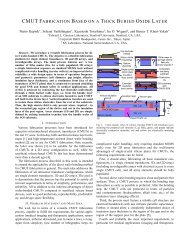
fabricated [2]–[6]. Fig. 1 shows some of the CMUT arrays we<br />
fabricated recently. Another advantage of CMUTs is in the<br />
convenient integration with front-end electronics [1]. Each of<br />
the CMUT arrays in Fig. 1 has its own dedicated front-end<br />
electronics packaged in an application-specific integrated<br />
circuit (ASIC) and very closely integrated with the transducers<br />
[2]–[6]. Some of these ASICs contain only signal conditioning<br />
circuitry for buffering the received signals, while the others<br />
also include more complex circuitry to transmit pulses and<br />
perform transmit beamforming.<br />
(a)<br />
(c)<br />
Conventional ultrasound imaging systems are designed for<br />
standard transducer arrays with regular geometry and simple<br />
front-end electronics, and are not suitable for probes with nonstandard<br />
aperture geometry or customized front-end electronics.<br />
The objective of our imaging system is to perform real-time<br />
imaging with various CMUT probes with different geometry<br />
and different front-end electronics, and demonstrate volumetric<br />
imaging for probes with 2-dimensional apertures, such as ring<br />
arrays and rectangular arrays. Multiple beamforming methods,<br />
including classic phased array (CPA), synthetic phased array<br />
(SPA), and plane-wave compounding, should be available<br />
because the optimal beamforming method for real-time<br />
imaging differs from probe to probe, depending on the aperture<br />
geometry and the number of elements in the array, and from<br />
application to application. In addition, we plan to use this<br />
imaging system in photoacoustic imaging as well.<br />
We describe the overall system design and the important<br />
system components in Section II, and some of the imaging<br />
results obtained using this system are presented in Section III.<br />
In Section IV, we briefly discuss the frame rate and the system<br />
tradeoffs.<br />
II.<br />
16 16-<br />
Element<br />
CMUT<br />
Array<br />
SYSTEM DESIGN<br />
Integrated<br />
Circuit<br />
Figure 1. Various CMUT arrays with different geometry and electronics.<br />
(a) 64-element ring array (b) 16×16-element rectangular array (c) 24-element<br />
micro-linear array (d) 132-element linear array<br />
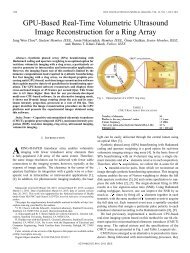
The system consists of an ultrasound data acquisition<br />
system (Verasonics data acquisition system, Verasonics, Inc.,<br />
Redmond, WA), a host PC (Mac Pro, Apple Inc., Cupertino,<br />
CA), an FPGA board (Virtex-6 FPGA ML605, Xilinx Inc., San<br />
Jose, CA), a laser (Surelite OPO Plus, Continuum, Santa Clara,<br />
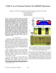
CA), and a custom-designed interface PCB. The top-level<br />
architecture of the overall system is shown in Fig. 2.<br />
(b)<br />
(d)
(a)<br />
(b)<br />
Figure 2. Top-level architecture of the system.<br />
The Verasonics data acquisition system acquires the RF<br />
data received by the transducers and pre-amplified by the frontend<br />
electronics. It has 128 transmit channels and 64 receive<br />
channels that we can program using Matlab scripts. The<br />
acquired data are transferred, via an 8-lane PCI express (PCIe)<br />
interface at a 1.2-GB/s transfer rate, to the host PC, on which<br />
our custom software developed in C++ runs to reconstruct<br />
images and display them on the screen in real-time. The host<br />
PC has 16-GB RAM, two quad-core (8 virtual cores with<br />
hyper-threading) 3-GHz CPUs (Intel Xeon Processor X5570,<br />
Intel Corporation, Santa Clara, CA), and a GPU (GeForce GTX<br />
285, Nvidia, Santa Clara, CA). Currently the software runs<br />
only on CPU, and the next version of software that utilizes<br />
GPU is now under development.<br />
Different options are available for transmit. In the simplest<br />
cases where the front-end electronics just performs signal<br />
conditioning and pre-amplification of received signals, the<br />
pulsers in the Verasonics system can be used to transmit pulses.<br />
For the probes with their own pulsers in the front-end IC, we<br />
program the FPGA to generate transmit delay data and control<br />
the on-chip pulsers for transmit beamforming. The delay data,<br />
quantized with a 20-ns resolution, are loaded into the front-end<br />
IC at a 50-MHz rate, resulting in a 2.56-μs loading time per<br />
beam. In photoacoustic imaging, the laser is used for excitation<br />
instead of pulsers. When the Verasonics transmitters are not<br />
used, we run the Verasonics in the external trigger mode to use<br />
it as a receiver and sample the raw data received by transducers.<br />
The individual system components are connected together<br />
by the custom-designed interface PCB, which also provides an<br />
interface to CMUT probes and power supplies. For<br />
synchronization of the system components, the FPGA<br />
generates and distributes clock and trigger signals.<br />
III.<br />
IMAGING RESULTS<br />
A. Ring Array Imaging<br />
Multiple imaging methods, including flash, CPA, SPA,<br />
SPA-W (SPA with aperture weighting), SPA-H (SPA with<br />
Hadamard coding), and SPA-HW (SPA with both aperture<br />
weighting and Hadamard coding), were tested for real-time<br />
(c)<br />
(e)<br />
(g)<br />
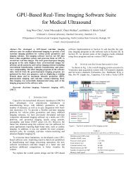
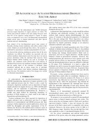
Figure 3. B-mode images of a phantom with 10 fishing wires, for six<br />
different imaging methods with a ring array, shown in 40-dB dynamic range.<br />
(a) Picture of the phantom in an oil tank (b) Location of each wire target<br />
(c) Flash (d) CPA (e) SPA (f) SPA-W (g) SPA-H (h) SPA-HW<br />
volumetric imaging with a 64-element ring array [Fig. 1 (a)]. In<br />
flash imaging, only one beam is transmitted in each frame<br />
without any delay. It is the fastest imaging method, but has a<br />
poor image resolution, especially in off-axis region because the<br />
beam is self-focused along the axis due to the circular<br />
symmetry of the ring geometry. CPA achieves a good<br />
resolution and a good SNR. However, it requires a large<br />
number of beams to sample the entire volume of interest<br />
without undersampling, resulting in a very slow frame rate and<br />
a need for immense memory space. In addition, due to the<br />
absence of transducer elements in the center of the ring, this<br />
method has a problem with high sidelobes. Using SPA, we can<br />
obtain an excellent beam profile with dynamic focusing in both<br />
transmit and receive, hence an excellent resolution, with a<br />
number of firings as small as the number of elements. SPA<br />
suffers from a low SNR, but it can be overcome by spatial<br />
pulse-encoding technique such as Hadamard coding [7], [8].<br />
Another advantage of SPA is that we can apply an aperture<br />
weighting scheme to obtain an effective full-disk aperture, for<br />
improved beam profile with lower sidelobes [9], [10].<br />
(d)<br />
(f)<br />
(h)
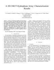
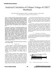
Figure 4. The custom software user interface, and real-time images of the fishing wire phantom, obtained with a 16×16-element rectangular array, using 625<br />
focused beams. For transmit, we used unipolar pulses from the on-chip pulsers with 25-V amplitude and single cycle. The numbers in the Pulse Control panel are<br />
not used when the pulses are transmitted from the on-chip pulsers.<br />
Fig. 3 presents B-mode images of an experimental phantom<br />
with 10 fishing wires, obtained using the six different imaging<br />
methods. From these experiments, we concluded that SPA-HW<br />
is the best option for real-time volumetric imaging with a ring<br />
array, which gives a good SNR, an excellent resolution, and a<br />
satisfactory frame rate. Using SPA-HW, we could achieve a<br />
frame rate of about 10 frames per second (fps) while displaying<br />
3 image planes, two B-mode planes perpendicular to each other<br />
and one constant-depth image, in real-time. More discussion on<br />
the frame rate follows in Section IV.<br />
B. Rectangular Array Imaging<br />
The CMUT rectangular array we used in the experiment<br />
consists of 256 transducer elements [Fig. 1 (b)]. The front-end<br />
IC contains 256 pulsers and transmit beamforming circuitry,<br />
but has only 16 receive channels. A receive channel is shared<br />
between the 16 elements on the same column, and only 16<br />
elements can receive simultaneously at each acquisition. So,<br />
instead of receiving from the full aperture, we used only 32<br />
diagonal elements for receive [11], by transmitting every beam<br />
twice and receiving from one of the two diagonals at each<br />
acquisition. The on-chip pulsers and the transmit beamforming<br />
circuitry are controlled by the FPGA, which also selects the<br />
receiving elements in each acquisition.<br />
We used CPA with 625 focused beams generated by the onchip<br />
transmit circuitry to sample the volume of interest. The<br />
maximum number of acquisitions per frame is restricted by the<br />
Verasonics sequencer memory, and we can transmit only up to<br />
697 beams with two acquisitions per beam. To avoid spatial<br />
undersampling, the viewing angle was limited to 50° in the<br />
experiment. Fig. 4 shows the resulting real-time images of the<br />
same wire phantom as in the ring array imaging, along with the<br />
user interface of our custom-developed software. Here, the<br />
images are shown in linear scale without compression. With<br />
625 beams and two acquisitions per beam, a 5.4-fps frame rate<br />
was achieved for displaying two B-mode images perpendicular<br />
to each other and one constant-depth image at 15-mm depth.<br />
C. Linear Array Imaging<br />
Real-time imaging using the first 64 channels of a 132-<br />
element CMUT linear array with elevational focus at 11 mm<br />
[Fig. 1 (d)] was demonstrated. A human neck was imaged<br />
using CPA with 91 focused beams on the B-mode plane. With<br />
a frame rate of 46 fps, we could clearly see the jugular vein<br />
pulsating. A captured B-mode image is presented in Fig. 5.<br />
Figure 5. B-mode image of a human neck, shown in 45-dB dynamic range.<br />
Pulsating jugular vein is clearly seen in the real-time image with a 46-fps<br />
frame rate.
TABLE I. FRAME RATES OF CPA WITH A RECTANGULAR ARRAY<br />
Number of beams 1 625 182 92 62<br />
Frame rate 2 5.4 19 37 54<br />
1 Each beam was transmitted twice to receive from both diagonals.<br />
2 Frame rates are in frames per second (fps).<br />
To improve the frame rate in synthetic imaging, we are<br />
currently developing new imaging software that performs<br />
image reconstruction on GPU platform for faster computation.<br />
Also, we are now working on real-time volumetric imaging for<br />
larger rectangular arrays, with 32×32 and 64×64 elements.<br />
TABLE II. FRAME RATES OF SPA WITH A RING ARRAY<br />
Number of pixels<br />
per plane<br />
22,801<br />
(High resolution)<br />
11,201<br />
(Low resolution)<br />
Number of planes 3 2 1 3 2 1<br />
Using 4,096 A-scans 1 9 12 20 17 21 28<br />
Using 1,560 A-scans 2 20 26 35 32 38 45<br />
1 Using all the A-scans from 64 transmit and 64 receive elements<br />
2 Discarding 2,536 A-scans with a weight less than 0.5 after aperture weighting<br />
1,2 Frame rates are in frames per second (fps).<br />
ACKNOWLEDGMENT<br />
This work is funded by the National Institute of Health<br />
under grants HL67647 and CA134720. Xilinx and Nvidia<br />
generously donated the FPGA board and GPU, respectively.<br />
We would like to thank Verasonics, Inc. for providing technical<br />
support. We also thank the <strong>Stanford</strong> Nanofabrication Facility<br />
for CMUT fabrication, and National Semiconductor (Texas<br />
Instrument) for IC fabrication.<br />
IV.<br />
SYSTEM TRADEOFFS<br />
Other than the ultrasound time of flight, the imaging system<br />
imposes practical limitations on real-time imaging performance.<br />
The data obtained using the Verasonics data acquisition system<br />
are transferred to the host PC for image reconstruction via an 8-<br />
lane PCIe interface. The data transfer rate, which is limited by<br />
the PCIe to local bus translator chip (PEX 8311, PLX<br />
Technology, Sunnyvale, CA), is 1.2 GB/s, a rate that is 4.8<br />
times slower than the data acquisition assuming 45-MHz data<br />
sampling. Therefore, in all imaging methods, the data transfer<br />
rate from the Verasonics data acquisition system to the host PC<br />
limits the achievable frame rate, and in many cases, including<br />
CPA, this is the actual bottleneck determining the frame rate.<br />
To alleviate this limitation and increase the frame rate, the<br />
amount of data transferred should be reduced, either by<br />
decreasing the imaging depth, or by reducing the number of<br />
data acquisitions per frame. Table I shows the experimental<br />
frame rates with different number of beams in CPA imaging,<br />
under the same imaging depth of 25 mm with 5-MHz<br />
transducers and 22.5-MHz sampling frequency. With fewer<br />
beams, the frame rate increases linearly, but at the cost of<br />
degraded image quality.<br />
In synthetic imaging, where the amount of computation is<br />
very large, the computational load required for image<br />
reconstruction exceeds the overhead in data transfer, and limits<br />
the frame rate further. Thus, to increase the frame rate of SPA,<br />
the amount of computation should be reduced by decreasing<br />
the number of pixels processed or the number of A-scans used<br />
in the delay-and-sum operations, as shown in Table II. The<br />
computation speed can be improved by upgrading hardware,<br />
for example, using more number of CPU cores or using a GPU<br />
with many parallel cores in the computation [12].<br />
V. CONCLUSION AND FUTURE WORK<br />
We designed and implemented a real-time volumetric<br />
imaging system that works with various types of CMUT probes<br />
with different geometry and different electronics. The system is<br />
capable of real-time imaging with multiple beamforming<br />
techniques, including non-standard methods as well as<br />
conventional methods. Real-time imaging using this system<br />
with a ring array, a rectangular array, and a linear array were<br />
demonstrated.<br />
REFERENCES<br />
[1] Ö. Oralkan, A. S. Ergun, J. A. Johnson, U. Demirci, M. Karaman, K.<br />
Kaviani, T. H. Lee, and B. T. <strong>Khuri</strong>-<strong>Yakub</strong>, “Capacitive micromachined<br />
ultrasonic transducers: Next-generation arrays for acoustic imaging,”<br />
IEEE Trans. Ultrason., Ferroelect., Freq. Contr., vol. 49, no. 11, pp.<br />
1596–1610, Nov. 2002.<br />
[2] J. Knight, J. McLean, and F. L. Degertekin, “Low temperature<br />
fabrication of immersion capacitive micromachined ultrasonic<br />
transducers on silicon and dielectric substrates,” IEEE Trans. Ultrason.,<br />
Ferroelect., Freq. Contr., vol. 51, no. 10, pp. 1324–1333, Oct. 2004.<br />
[3] A. Nikoozadeh, I. O. Wygant, D. Lin, Ö. Oralkan, A. S. Ergun, D. N.<br />
Stephens, K. E. Thomenius, A. M. Dentinger, D. Wildes, G. Akopyan,<br />
K. Shivkumar, A. Mahajan, D. J. Sahn, and B. T. <strong>Khuri</strong>-<strong>Yakub</strong>,<br />
"Forward-looking intracardiac ultrasound imaging using a 1-D CMUT<br />
array integrated with custom front-end electronics," IEEE Trans.<br />
Ultrason., Ferroelect., Freq. Contr., vol. 55, no. 12, pp. 2651–2660,<br />
Dec. 2008.<br />
[4] A. Nikoozadeh, Ö. Oralkan, M. Gencel, J. W. Choe, D. N. Stephens, A.<br />
de la Rama, P. Chen, K. Thomenius, A. Dentinger, D. Wildes, K.<br />
Shivkumar, A. Mahajan, M. O’Donnell, D. Sahn, and P. T. <strong>Khuri</strong>-<br />
<strong>Yakub</strong>, “Forward-looking volumetric intracardiac imaging using a fully<br />
integrated CMUT ring array,” in Proc. IEEE Ultrason. Symp., pp. 511–<br />
514, 2009.<br />
[5] I. Wygant, X. Zhuang, D. Yeh, Ö. Oralkan, A. S. Ergun, M. Karaman,<br />
and B. T. <strong>Khuri</strong>-<strong>Yakub</strong>, "Integration of 2D CMUT arrays with front-end<br />
electronics for volumetric ultrasound imaging," IEEE Trans. Ultrason.,<br />
Ferroelect., Freq. Contr., vol. 55, no. 2, pp. 327–342, Feb. 2008.<br />
[6] I. O. Wygant, N. S. Jamal, H. J. Lee, A. Nikoozadeh, Ö. Oralkan, M.<br />
Karaman, and B. T. <strong>Khuri</strong>-<strong>Yakub</strong>, , "An integrated circuit with transmit<br />
beamforming flip-chip bonded to a 2-D CMUT array for 3-D ultrasound<br />
imaging," IEEE Trans. Ultrason., Ferroelect., Freq. Contr., vol. 56, no.<br />
10, pp. 2145–56, , Oct. 2009.<br />
[7] R. Y. Chiao, L. J. Thomas, and S. D. Silverstein, “Sparse array imaging<br />
with spatially-encoded transmits,” in Proc. IEEE Ultrason. Symp., vol.<br />
2, pp. 1679–1682, 1997.<br />
[8] T. X. Misaridis and J. A. Jensen, “Space-time encoding for high frame<br />
rate ultrasound imaging,” <strong>Ultrasonics</strong>, vol. 40, pp. 593–597, May 2002.<br />
[9] S. J. Norton, “Annular array imaging with full-aperture resolution,” J.<br />
Acoust. Soc. Am., vol. 92, no. 6, pp. 3202–3206, Dec. 1992.<br />
[10] S. J. Norton, “Synthetic aperture imaging with arrays of arbitrary shape.<br />
Part II: The annular array,” IEEE Trans. Ultrason., Ferroelect., Freq.<br />
Contr., vol. 49, pp. 404–408, Apr. 2002.<br />
[11] M. Karaman, I. O. Wygant, Ö. Oralkan, and B. T. <strong>Khuri</strong>-<strong>Yakub</strong>,<br />
"Minimally redundant 2-D array designs for 3-D medical ultrasound<br />
imaging ," IEEE Trans. Medical Imaging, vol. 28, no. 7, pp. 1051–1061,<br />
Jul. 2009.<br />
[12] B. Yiu, I. Tsang, and A. Yu, “Real-time GPU-based software<br />
beamformer designed for advanced imaging methods research,” in Proc.<br />
IEEE Ultrason. Symp., pp. 1920–1923, 2010.