(CMUT) as a chemical sensor for DMMP detection - Khuri-Yakub ...
(CMUT) as a chemical sensor for DMMP detection - Khuri-Yakub ...
(CMUT) as a chemical sensor for DMMP detection - Khuri-Yakub ...
- No tags were found...

You also want an ePaper? Increase the reach of your titles
YUMPU automatically turns print PDFs into web optimized ePapers that Google loves.
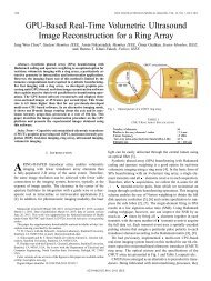
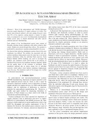
1122 K.K. Park et al. / Sensors and Actuators B 160 (2011) 1120–1127Fig. 2. Optical pictures of a <strong>CMUT</strong> array. (a) 64 sensing units (element) are located in a 5 mm × 2.5 mm die. (b) Top view of three elements. Circular pattern represents manyunit resonators (Fig. 1) in a single element. In order to reduce the mechanical cross talk between elements, through-wafer isolation trenches are used between elements.sheet resistance of 20 /□. As a result the effective m<strong>as</strong>s of plateis reduced. Moreover, the single crystal plate transferred froman SOI wafer h<strong>as</strong> a better thickness uni<strong>for</strong>mity and lower residualstress compared to the silicon nitride plate <strong>for</strong>med using theLPCVD process. The new process provides precise control of theplate dimensions, such <strong>as</strong> a plate thickness and a cavity shape, andalso the process is capable of fabricating a very thin vacuum cavity<strong>as</strong> low <strong>as</strong> 40 nm. This low value <strong>for</strong> the cavity height reduces therequired DC bi<strong>as</strong> voltage to establish a high electric field strengththat results in a good electromechanical coupling.2.2.2. Structure of multi-resonatorsA single <strong>CMUT</strong> <strong>sensor</strong> unit (channel) is composed of 100s to1000s of identical resonant structures. These resonators in thechannel are designed not to be mechanically coupled to each other,but to be electrically connected in parallel. There<strong>for</strong>e, one can electricallyaccess the parallel combination of all resonators throughtwo bond pads, i.e., a signal and a ground pad (Fig. 2). The 18 MHzresonator used <strong>for</strong> the <strong>chemical</strong> <strong>detection</strong> is composed of 1000 resonators,each made of a single crystal silicon plate with a radius of9 m and a thickness of 0.5 m.This multi-resonator configuration h<strong>as</strong> several benefits over thesingle resonator configuration. First, the effect on the lumped signaldue to a failure of a few resonators during operation is not significant.As a result, the <strong>sensor</strong> is reliable and operational even withminor external damage. In addition, a larger number of resonatorsresult in a larger total effective capacitance of the device. As a result,the ratio of unwanted par<strong>as</strong>itic capacitance due to electrical signalpads and external bond-wires to the active device capacitancebecomes smaller. Moreover, the number of resonators can be used<strong>as</strong> an additional design parameter to adjust the lumped impedanceof the device. For example, the lumped motional impedance is acritical parameter in the oscillator design in terms of thermal noiseand impedance matching. This motional impedance is inverselyproportional to the number of resonators and can be adjusted withoutchanging the dimensions of individual resonators [18].2.3. Device characterization<strong>CMUT</strong> resonators are characterized electrically using animpedance analyzer (Model 4294A, Agilent Technologies, SantaClara, CA). Important parameters of the resonant structure, such <strong>as</strong>the series and parallel resonant frequencies and Q, are extractedfrom this me<strong>as</strong>urement. The me<strong>as</strong>ured input impedance of the<strong>CMUT</strong> (Fig. 3) shows a series resonant frequency of 17.3 MHz and aparallel resonant frequency of 18.2 MHz.In an ideal resonator model, Q of both resonant frequenciesshould be comparable [16]. However, <strong>as</strong> the <strong>CMUT</strong> is made of multipleresonators connected in parallel, the resonator-to-resonatornon-uni<strong>for</strong>mity affects the quality factor. As Lee [19] discussed, thedegradation of the quality factor of the series resonant frequencyis more severe than that of the parallel resonant frequency, whichis also observed in our me<strong>as</strong>urement (Fig. 3). The me<strong>as</strong>ured qualityfactor of series resonant frequency (27) is much lower thanFig. 3. (a) Me<strong>as</strong>ured input impedance of 18-MHz <strong>CMUT</strong>. (b) 6-elements equivalent circuit model with extracted component values from (a).
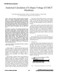
K.K. Park et al. / Sensors and Actuators B 160 (2011) 1120–1127 1123of a 50 nm polymer film on the quality factor and the resonant frequencyof the device is negligible b<strong>as</strong>ed on the input impedanceme<strong>as</strong>urement. The parallel resonant frequency slightly is incre<strong>as</strong>edby 0.64% while the quality factor is decre<strong>as</strong>ed by 7 after the polymerdeposition.Compared to the spin coating method, the inkjet-dispensingmethod tends to have less uni<strong>for</strong>mity across the active area. However,the inkjet-dispensing method can selectively pattern are<strong>as</strong>of interest, e.g., top side of <strong>CMUT</strong> plates of a single device, andcoat different polymers on multiple devices in a single die <strong>for</strong> arrayimplementation [11].2.5. Detection systemFig. 4. Photograph of inkjet polymer coating. Cylinder on the top of the picture ismicro-capillary used <strong>as</strong> droplet ejection. In this photograph, the solvent containinga polymer on the center element is not dried yet.that of parallel resonant frequency (140) due to the resonator-toresonatornon-uni<strong>for</strong>mity. To avoid low Q at the series resonantfrequency, the oscillator circuit is designed to oscillate at the parallelresonant frequency.2.4. Chemical functionalizationThe resonators must be functionalized with a sorbent film toabsorb analytes in air. This sorbent film should have high sensitivityand good selectivity to the analyte of interest. Among several commerciallyavailable polymers such <strong>as</strong> polyallylamine hydrochloride(PAAM), polyethylene glycol (PEG), and polyvinyl alcohol (PVA), weselected polyisobutylene (PIB) <strong>as</strong> the sorbent film to detect <strong>DMMP</strong>because of its availability and higher sensitivity to <strong>DMMP</strong> [20].Diluted droplets of PIB (in toluene, 1 mg/ml), each with avolume of 0.2 nl, were ejected on the 18 MHz device using aninkjet-dispensing system (model MD-P-801, Microdrop, Norderstedt,Germany) [21]. The ejected droplets con<strong>for</strong>mally coated thesurface of the <strong>CMUT</strong> (Fig. 4). Then the solvent evaporated in a fewseconds leaving a thin layer of polymer. It is challenging to me<strong>as</strong>urethe thickness of this polymer film using optical methods becausethe coated film is thin and optically transparent; only a particlepattern (Fig. 5) indicates the edge of the polymer coating. Thus,using atomic <strong>for</strong>ce microscope (AFM), operated in tapping mode,we me<strong>as</strong>ured the thickness of the polymer to be 50 nm. The effectFig. 5. Optical picture of a <strong>CMUT</strong> after functionalization. Small dotted line representsthe edge of the polymer coating.An accurate me<strong>as</strong>urement of the resonant frequency is an essentialpart of a highly sensitive <strong>sensor</strong> system; lower frequencynoise will result in lower limit of <strong>detection</strong> level of the system.The resonant frequency can be determined through the electricalinput impedance me<strong>as</strong>urement. However, this method suffersfrom limited frequency-sweep resolution and slow response time.There<strong>for</strong>e, we designed a low noise oscillator circuit that tracks theresonant frequency of the device. This method allows <strong>for</strong> accuratereal-time me<strong>as</strong>urements using a digital frequency counter connectedto the output of the oscillator circuit.2.5.1. Oscillator circuit designThe oscillator circuit is composed of the <strong>CMUT</strong> <strong>as</strong> well <strong>as</strong> otherdiscrete circuit components. For an optimal design, the circuit couldbe simulated and optimized in design steps. During these steps,the me<strong>as</strong>ured input impedance (Fig. 3a) could be modeled in anappropriate <strong>for</strong>mat and incorporated in the circuit simulation. Inthis work, we modeled the input impedance of the device <strong>as</strong> a6-elements circuit model <strong>as</strong> shown in Fig. 3b. The model consistsof the conventional 4-element RLC model (Rx, Lx, Cx, and Co) andadditional two elements, Cc, and Rc. The 4-element RLC model isknown <strong>as</strong> Butterworth Van Dyke model and commonly used <strong>as</strong> anequivalent circuit model <strong>for</strong> MEMS resonators. The additional twoelements (i.e. Cc and Rc) represent the contact capacitance and thecontact resistance to the substrate. The values of six elements wereextracted from the me<strong>as</strong>ured input impedance b<strong>as</strong>ed on a le<strong>as</strong>tsquares fitting method (Fig. 3a).Compared to other MEMS resonators and quartz-b<strong>as</strong>ed resonators,<strong>CMUT</strong> resonators have two characteristics that govern theoscillator design. First, the <strong>CMUT</strong> is a one-port resonator, i.e., it h<strong>as</strong>two electrical pads, a signal pad and a ground pad. This configurationgives more limitation of the topology of the oscillation circuit,compared to other two-port MEMS resonators [22,23]. Second, allthe resonator units (elements) share the substrate <strong>as</strong> a commonground. There<strong>for</strong>e the oscillator circuit, which is required to becompatible with the multi-channel oscillator, can access only oneelectrode of the <strong>CMUT</strong>, and leave the other electrode connectedto ground. L<strong>as</strong>t, <strong>as</strong> previously mentioned, the quality factor of theparallel resonant frequency of the <strong>CMUT</strong> is higher than that of theseries resonant frequency. The circuit is designed to oscillate at theparallel resonant frequency to take advantage of higher Q.B<strong>as</strong>ed on the above criteria, an oscillator circuit w<strong>as</strong> designedand implemented (Fig. 6). The <strong>CMUT</strong> resonator w<strong>as</strong> interfaced tothe circuit through a voltage divider. The value of the capacitor inthis stage w<strong>as</strong> chosen to optimize the tradeoff between in-circuitQ and the gain of the voltage divider. The gain stage and band-p<strong>as</strong>sfilter were implemented using low noise op-amps (AD8045 andOPA657) to satisfy the Barkhausen criteria. The implemented circuitrequires only two op-amps inside the oscillation loop, with atotal power consumption of 80 mW. The loop gain is sufficientlylarger than unity around the resonant frequency to start the oscillationfrom in-circuit noise components, and thus the system does
1124 K.K. Park et al. / Sensors and Actuators B 160 (2011) 1120–1127Fig. 6. (a) Schematic of the oscillator circuit including a <strong>CMUT</strong>. (b) Optical picture of a populated oscillator circuit on PCB.not require an additional start-up circuit. The <strong>CMUT</strong> is directlymounted on a printed circuit board (PCB) without a chip-carrierand wire-bonded on the PCB to reduce par<strong>as</strong>itic capacitance.2.5.2. Per<strong>for</strong>mance of the oscillatorThe free running oscillation frequency of the circuit w<strong>as</strong> me<strong>as</strong>uredusing an external digital frequency counter (Model SRS620,Stan<strong>for</strong>d Research System, Sunnyvale, CA) with a typical gate timeof 10 ms, i.e., 100 frequency samples per a second. Frequency in<strong>for</strong>mationis transferred to an external PC <strong>for</strong> signal processing. Thetime delay between the counter and the PC is less than 100 ms,which is short enough <strong>for</strong> a real-time me<strong>as</strong>urement of the frequencyshift due <strong>chemical</strong> absorption.The amount of frequency shift is proportional to the amount of<strong>chemical</strong> absorption. As a result, the limit of <strong>detection</strong> of the outputsignal, i.e., frequency noise level, decides the limit of <strong>detection</strong>of analyte concentration in air. In order to quantify the frequencynoise level, we used the Allan deviation method [24], which is acommon method to me<strong>as</strong>ure the short-term frequency stabilityof timing references. The Allan deviation number, y (n 0 ,M), <strong>for</strong>a given gate time, n 0 , is√√ y (n 0 , M) =√ 12n 2 (M − 2n + 1)∑M−2n j+n−1( ¯f i+n − ¯f i ) 2 , (4)j=0∑where 0 is the gate time of the frequency me<strong>as</strong>urement, M is totalnumber of samples and ¯f i is the averaged frequency of n-samples.This method averages neighboring frequency samples to computedeviation at a given averaging time, n 0 , (i.e., effective gate time). Ina short averaging time, the Allan deviation tends to decre<strong>as</strong>e withmore averaging time. However, the Allan deviation incre<strong>as</strong>es whenthe averaging time is larger than a certain value, because the driftof the resonant frequency (i.e., mid-term frequency noise) startsto dominate the frequency variation. We me<strong>as</strong>ured a large numberof finely spaced frequency samples and computed the Allandeviation <strong>for</strong> various averaging times to find the optimal averagingtime (Fig. 7). The oscillator h<strong>as</strong> the lowest Allan deviation( y /f) of 2.74 × 10 −8 at 50 ms averaging time, which correspondsto a frequency noise level of 0.5 Hz. B<strong>as</strong>ed on Eq. (3), the <strong>sensor</strong>’sminimum <strong>detection</strong> limit of loaded m<strong>as</strong>s per unit area ( min /A) is1.92 × 10 −11 kg/m 2 or 0.192 ag/m 2 with 3- confidence levels.i=jand bubblers [11,25]. Purified air from a zero air generator (Model76-803, Balston Parker, Haverhill, MA) w<strong>as</strong> used to provide flowthrough two MFCs. These two MFCs separately control the flow rateof the carrier air and flow rate of the air injected into a bubbler. Inthe bubbler, the air flows through a liquid-ph<strong>as</strong>e analyte, resultingin evaporation of the analyte into the air. The air containinganalyte molecules is then mixed with the carrier air. This mixtureg<strong>as</strong> is transferred into a 3 cm 3 gl<strong>as</strong>s chamber, which encloses thepolymer-coated <strong>CMUT</strong> resonator.The typical flow rates of the bubbler air is 1–10 ml/min and theflow rate of diluted air is adjusted in 499–490 ml/min to regulatethe total flow rate to 500 ml/min. The volume concentration of ananalyte is calculated b<strong>as</strong>ed on three parameters: the flow rate of theair through the bubbler, flow rate of the carrier air and the vaporpressure of each analyte, <strong>as</strong>suming the output of the bubbler is fullysaturated with the analyte.3. Results3.1. Sensitivity and limit of <strong>detection</strong>We chose <strong>DMMP</strong> <strong>as</strong> our main analyte and ethanol and water<strong>as</strong> reference analytes. Fig. 8 shows transient responses of the frequencyto different concentrations of three different analytes. Foreach me<strong>as</strong>urement, the analyte molecules were injected into thechamber at 60 s by flowing air through the bubbler containing<strong>DMMP</strong>. The PIB coating absorbs the analyte molecules until itreaches an equilibrium condition <strong>for</strong> the given analyte concentration.The m<strong>as</strong>s of the absorbed molecules shifts the resonant2.6. Experimental setupThe volume sensitivity is me<strong>as</strong>ured using an in-house <strong>chemical</strong>set-up that can deliver low vapor concentrations of <strong>DMMP</strong>. Theexperimental setup consists of several m<strong>as</strong>s flow controllers (MFC)Fig. 7. Allan deviation y of the oscillator circuit in Fig. 6(b).
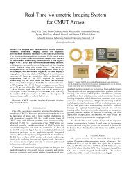
K.K. Park et al. / Sensors and Actuators B 160 (2011) 1120–1127 1125Fig. 9. Frequency shift of PIB coated <strong>CMUT</strong> in response to several analytes in differentconcentrations.B<strong>as</strong>ed on the me<strong>as</strong>ured noise level of the oscillation circuit (0.5 Hz),the equivalent volume resolution of <strong>detection</strong> <strong>for</strong> <strong>DMMP</strong> is 56 ppbwith 3- confident levels.3.2. Analyte identificationWe per<strong>for</strong>med principal component analysis (PCA), a commonpattern recognition algorithms used <strong>for</strong> analyte identification, tomaximize the in<strong>for</strong>mation extracted from the me<strong>as</strong>urements. Thetransient frequency shifts <strong>for</strong> different analytes exhibit distinctivepatterns (i.e., fingerprints), such <strong>as</strong> fall and rise time constants(Figs. 8 and 10) <strong>as</strong> observed in the <strong>chemical</strong> <strong>sensor</strong> b<strong>as</strong>ed on amicro-cantilever array [26]. Five different data points between 60 sand 180 s were extracted from each curve and normalized by themaximum frequency shift (Fig. 8). These data points were used <strong>as</strong>an input dat<strong>as</strong>et to the PCA [26]. The PCA of 21 experiments successfullyseparated three analytes (Fig. 11); the PCA plot shows awide distribution of points <strong>for</strong> a single analyte because we use <strong>as</strong>ingle <strong>sensor</strong>. Accuracy of identification can be improved by usinga functionalized array of <strong>sensor</strong>s <strong>as</strong> we previously per<strong>for</strong>med withthe lower-frequency <strong>CMUT</strong> resonators [11].3.3. RepeatabilityRepeatability is another important figure of merit of a <strong>sensor</strong>system. We per<strong>for</strong>med a long-term experiment to demonstrateFig. 8. Frequency response of the PIB coated <strong>CMUT</strong> <strong>chemical</strong> <strong>sensor</strong> to (a) <strong>DMMP</strong>(b) ethanol (c) water.frequency downwards from its initial frequency of 18 MHz. Thischemi-absorption process is reversible; the resonant frequencystarts to recover back to the b<strong>as</strong>eline when the flow through thebubbler is stopped at 180 s.Fig. 9 demonstrates that the amount of frequency shift isproportional to different concentrations of the analytes (i.e., theamounts of the loaded molecules). The volume sensitivity iscalculated b<strong>as</strong>ed on the linear fitting between the amounts offrequency shifts with respect to various volume concentrations.The calculated volume sensitivities to <strong>DMMP</strong>, water, and ethanolare 37 ppb/Hz, 239 ppb/Hz, and 2600 ppb/Hz, respectively. Thelinearity in sensitivity illustrates that <strong>for</strong> the tested concentrationrange, the PIB coating (∼50 nm) is not in the saturation region.Fig. 10. Normalized frequency response of the PIB coated <strong>CMUT</strong> to three differentanalytes.
1126 K.K. Park et al. / Sensors and Actuators B 160 (2011) 1120–1127The causes of the variation me<strong>as</strong>ured in the long-term experimentinclude systematic errors in the experimental setup. For example,the MFC h<strong>as</strong> a limited accuracy of 1% flow rate and it h<strong>as</strong> a variationof a response time in opening and closing valves.4. DiscussionFig. 11. PCA of three analytes from Fig. 8. Each point represents the different concentrationof the analyte.the repeatability of the <strong>sensor</strong> system, including the durability ofthe resonant structure and the polymer. The <strong>DMMP</strong> vapor with aconcentration of 50 ppmv w<strong>as</strong> injected into the gl<strong>as</strong>s chamber <strong>for</strong>120 s and then the chamber w<strong>as</strong> purged with purified air. This cyclew<strong>as</strong> per<strong>for</strong>med 200 times over a time period of 26 h (Fig. 12a). The<strong>CMUT</strong> <strong>chemical</strong> <strong>sensor</strong> successfully responded to all <strong>DMMP</strong> injectionswithout any degradation of the output signal (Fig. 12b). Thefrequency shift of each pulse cycle showed that the volume sensitivityh<strong>as</strong> a 3- variation of 4.7% over the 26 h operation, confirmingnegligible degradation effects from the resonator and the polymer.Our m<strong>as</strong>s-loading <strong>sensor</strong> presented in this paper h<strong>as</strong> improvedin several ways from our previous work, which entailed the firstdemonstration of using a <strong>CMUT</strong> <strong>as</strong> a <strong>chemical</strong> <strong>sensor</strong> [11]. First,the m<strong>as</strong>s sensitivity h<strong>as</strong> been improved from 1 fg/Hz to 33 ag/Hzby optimizing the mechanical properties of the <strong>CMUT</strong> resonators.The device introduced in this paper is composed of a flexural platethat is less dense and thinner by factor of 1.37 and 1.70, respectively,compared to those of our previous <strong>CMUT</strong> <strong>sensor</strong> [11]. B<strong>as</strong>edon (2), these modifications have improved the m<strong>as</strong>s sensitivity perunit area by factor of 2.33. In addition, the higher operating frequencyand the reduced size of the individual resonator in thiswork improved the m<strong>as</strong>s sensitivity per a resonator approximatelyby another factor of 12. Second, despite the lower Q (140) thanthe Q of our previous work (250) at the parallel resonant frequency,improvements in the oscillator implementation, such <strong>as</strong>stringent ground shielding and reduction in par<strong>as</strong>itics that load the<strong>CMUT</strong> resonator, have allowed us to maintain a low noise level of2.74 × 10 −8 (Allan deviation, y /f).The <strong>CMUT</strong> still h<strong>as</strong> much room <strong>for</strong> improvements <strong>as</strong> a resonant<strong>chemical</strong> <strong>sensor</strong>. The density and plate thickness can be furtherreduced to incre<strong>as</strong>e the m<strong>as</strong>s sensitivity. In addition, the m<strong>as</strong>s resolutioncan be improved by incre<strong>as</strong>ing the resonator Q. The limitof <strong>detection</strong> is determined by the frequency noise of the system(3), which is inversely proportional to the resonator Q. There<strong>for</strong>e,a future resonator design must be optimized to achieve a higher Q.Moreover, the <strong>chemical</strong> sensitivity can be improved by using a moresensitive and selective functionalization material. In this paper, PIBw<strong>as</strong> selected <strong>as</strong> the <strong>chemical</strong>ly selective layer due to its availabilityand known sensitivity to <strong>DMMP</strong> [20], which allowed us to achievea limit of <strong>detection</strong> level of 56 ppb to <strong>DMMP</strong>. However, this resolutionis still 3.2 times higher than IDLH of sarin (17.5 ppb). Thevolume sensitivity can be dramatically improved to meet the IDLHlevel of sarin by adapting synthesized polymers specifically developed<strong>for</strong> the nerve g<strong>as</strong>es <strong>detection</strong> [27]. In addition, we coated thedevice with a very thin layer (50 nm) to minimize the effect of polymercoating on the device impedance. Applying a thicker layer ofpolymer may degrade Q of the device [28], but it can improve thevolume sensitivity of the system. There<strong>for</strong>e, the optimization of thepolymer thickness is also a part of our future work.5. ConclusionFig. 12. (a) Frequency shift during repeatability tests. (b) Amount of frequency shiftat each pulse in (a). 200 pulses correspond to 26.6 h.We presented a highly sensitive <strong>chemical</strong> <strong>sensor</strong> b<strong>as</strong>edon the <strong>CMUT</strong> technology with theoretical m<strong>as</strong>s sensitivity of130 zg/Hz/m 2 operating at 18.2 MHz. The inherent <strong>CMUT</strong> characteristics,such <strong>as</strong> the higher quality factor due to the vacuumcavity and the multi-resonator configuration, results in a lowerfrequency noise, a reliable operation, and a simple design of theoscillator circuit. In addition, the encapsulated gap allows thedevice to be not only fully compatible with the inkjet-dispensingmethod <strong>for</strong> the polymer coating, but also compatible with othergeneral functionalization methods (e.g., spin-coating, dip-coating,and pipette-dropping). With the low noise oscillator circuit design,we achieved an equivalent volume resolution of 56 ppb to <strong>DMMP</strong>with 3- confident levels. This work demonstrated that a sensitive,reliable, and portable <strong>chemical</strong> sensing system could be achievedusing an array of <strong>CMUT</strong> resonators. In addition, the <strong>CMUT</strong> resonator
K.K. Park et al. / Sensors and Actuators B 160 (2011) 1120–1127 1127with a higher resonant frequency and a synthesized polymer canachieve highly improved LOD in the order of ppt range.AcknowledgementThis work is funded by DARPA, Microsystems Technology Officeunder grant N66001-06-1-2030.References[1] N. Graber, H. Lüdi, H.M. Widmer, The use of <strong>chemical</strong> <strong>sensor</strong>s in industry,Sensors and Actuators B: Chemical 1 (1990) 239–243.[2] S.V. Patel, T.E. Mlsna, B. Fruhberger, E. Kla<strong>as</strong>sen, S. Cemalovic, D.R. B<strong>as</strong>elt, Chemicapacitivemicro<strong>sensor</strong>s <strong>for</strong> volatile organic compound <strong>detection</strong>, Sensors andActuators B: Chemical 96 (2003) 541–553.[3] D.M. Wilson, S. Hoyt, J. Janata, K. Booksh, L. Obando, Chemical <strong>sensor</strong>s <strong>for</strong>portable, handheld field instruments, Sensors Journal, IEEE 1 (2001) 256–274.[4] L. McKnight, K. McAfee, D. Sipler, Low-field drift velocities and reactions ofnitrogen ions in nitrogen, Physical Review 164 (1967) 62–70.[5] L.A. Pinnaduwage, D.L. Hedden, A. Gehl, V.I. Boiadjiev, J.E. Hawk, R.H. Farahi,T. Thundat, E.J. Houser, S. Stepnowski, R.A. McGill, L. Deel, R.T. Lareau, A sensitive,handheld vapor <strong>sensor</strong> b<strong>as</strong>ed on microcantilevers, Review of ScientificInstruments 75 (2004) 4554.[6] S. Bruckenstein, M. Shay, Experimental <strong>as</strong>pects of use of the quartz crystalmicrobalance in solution, Electrochimica Acta 30 (1985) 1295–1300.[7] A. Snow, H. Wohltjen, Poly(ethylene maleate)-cyclopentadiene: a model reactivepolymer-vapor system <strong>for</strong> evaluation of a SAW micro<strong>sensor</strong>, AnalyticalChemistry 56 (1984) 1411–1416.[8] H. Zhang, E.S. Kim, Micromachined acoustic resonant m<strong>as</strong>s <strong>sensor</strong>, Journal ofMicroelectromechanical Systems 14 (2005) 924–934.[9] F.M. Battiston, J.P. Ramseyer, H.P. Lang, M.K. Baller, Ch. Gerber, J.K. Gimzewski,E. Meyer, H.J. Guntherodt, A <strong>chemical</strong> <strong>sensor</strong> b<strong>as</strong>ed on a microfabricated cantileverarray with simultaneous resonance-frequency and bending readout,Sensors and Actuators B: Chemical 77 (2001) 122–131.[10] M. Li, H.X. Tang, M.L. Roukes, Ultra-sensitive NEMS-b<strong>as</strong>ed cantilevers <strong>for</strong>sensing, scanned probe and very high-frequency applications, Nature Nanotechnology2 (2007) 114–120.[11] K.K. Park, H. Lee, G.G. Yaralioglu, A.S. Ergun, O. Oralkan, M. Kupnik, C.F. Quate,B.T. <strong>Khuri</strong>-<strong>Yakub</strong>, T. Braun, J.-P. Ramseyer, H.P. Lang, M. Hegner, Ch. Gerber,J.K. Gimzewski, Capacitive micromachined ultr<strong>as</strong>onic transducers <strong>for</strong> <strong>chemical</strong><strong>detection</strong> in nitrogen, Applied Physics Letters 91 (2007) 094102.[12] A.S. Ergun, Y. Huang, X. Zhuang, O. Oralkan, G. Yarahoglu, B.T. <strong>Khuri</strong>-<strong>Yakub</strong>,Capacitive micromachined ultr<strong>as</strong>onic transducers: fabrication technology,ultr<strong>as</strong>onics, ferroelectrics and frequency control, IEEE Transactions on Ultr<strong>as</strong>onics,Ferroelectrics and Frequency Control 52 (2005) 2242–2258.[13] [13] Centers <strong>for</strong> Dise<strong>as</strong>e Control and Prevention (CDC), The EmergencyResponse Safety and Health Datab<strong>as</strong>e, Sarin (GB), http://www.cdc.gov/niosh/ershdb/EmergencyResponseCard 29750001.html.[14] L. Meirovitch, Analytical Methods in Vibrations, 1st ed., New York, Macmillan,1967.[15] M.J. Madou, Fundamentals of Microfabrication, 2nd ed., Boca Raton, CRC Press,2002.[16] J.R. Vig, Quartz Crystal Resonators and Oscillators, http://www.ieeeuffc.org/frequencycontrol/teaching/vig/vig3 files/frame.htm.[17] K.K. Park, H.J. Lee, M. Kupnik, B.T. <strong>Khuri</strong>-yakub, Fabrication of capacitive micromachinedultr<strong>as</strong>onic transducers via local oxidation and direct wafer bonding,Journal of Microelectromechanical Systems 20 (2011) 95–103.[18] H.J. Lee, K.K. Park, P. Cristman, O. Oralkan, M. Kupnik, B.T. <strong>Khuri</strong>-<strong>Yakub</strong>, Theeffect of parallelism of <strong>CMUT</strong> cells on ph<strong>as</strong>e noise <strong>for</strong> chem/bio <strong>sensor</strong> applications,IEEE Ultr<strong>as</strong>onics Symposium, IEEE (2008) 1951–1954.[19] H.J. Lee, K.K. Park, P. Cristman, O. Oralkan, M. Kupnik, B.T. <strong>Khuri</strong>-<strong>Yakub</strong>, A lownoiseoscillator b<strong>as</strong>ed on a multi-membrane <strong>CMUT</strong> <strong>for</strong> high sensitivity resonant<strong>chemical</strong> <strong>sensor</strong>s, in: Proceedings of 22nd IEEE MEMS Conference, 2009, pp.761–764.[20] B. Joo, J. Huh, D. Lee, Fabrication of polymer SAW <strong>sensor</strong> array to cl<strong>as</strong>sify <strong>chemical</strong>warfare agents, Sensors and Actuators B: Chemical 121 (2007) 47–53.[21] A. Bietsch, J. Zhang, M. Hegner, H.P. Lang, C. Gerber, Rapid functionalization ofcantilever array <strong>sensor</strong>s by inkjet printing, Nanotechnology 15 (2004) 873–880.[22] J.E.-Y. Lee, Y. Zhu, A.A. Seshia, A bulk acoustic mode single-crystal siliconmicroresonator with a high-quality factor, Journal of Micromechanics andMicroengineering 18 (2008) 064001.[23] R.N. Candler, M.A. Hopcroft, B. Kim, W.-T. Park, R. Melamud, M. Agarwal, G.Yama, A. Partridge, M. Lutz, T.W. Kenny, Long-term and accelerated life testingof a novel single-wafer vacuum encapsulation <strong>for</strong> MEMS resonators, Journal ofMicroelectromechanical Systems 15 (2006) 1446–1456.[24] D.A. Howe, D.W. Allan, J.A. Barnes, Properties of signal Sources and me<strong>as</strong>urementmethods, in: Annual Frequency Control Symposium, 35th, Philadelphia,PA, 1981, pp. 14–60.[25] T. Porter, M. E<strong>as</strong>tman, D. Pace, M. Bradley, Sensor b<strong>as</strong>ed on piezoresistive microcantilevertechnology, Sensors and Actuators A: Physical 88 (2001) 47–51.[26] H.P. Lang, J.P. Ramseyer, W. Grange, T. Braun, D. Schmid, P. Hunziker, C. Jung, M.Hegner, Ch. Gerber, An artificial nose b<strong>as</strong>ed on microcantilever array <strong>sensor</strong>s,Journal of Physics: Conference Series 61 (2007) 663–667.[27] J.W. Grate, D.A. Nelson, Sorptive polymeric materials and photopatternedfilms <strong>for</strong> g<strong>as</strong> ph<strong>as</strong>e <strong>chemical</strong> micro<strong>sensor</strong>s, Proceedings of the IEEE 91 (2003)881–889.[28] I. Dufour, F. Lochon, S.M. Heinrich, F. Josse, D. Rebiere, Effect of coating viscoel<strong>as</strong>ticityon quality factor and limit of <strong>detection</strong> of microcantilever <strong>chemical</strong><strong>sensor</strong>s, IEEE Sensors Journal 7 (2007) 230–236.BiographiesKwan Kyu Park received the B.S. degree in mechanical and aerospace engineeringfrom Seoul National University, Seoul, Korea, in 2001. He received the M.S. degreeand Ph.D. degree in mechanical engineering from Stan<strong>for</strong>d University, Stan<strong>for</strong>d, CA,in 2007 and in 2011 respectively. He h<strong>as</strong> been a Research Assistant in the Edward L.Ginzton Laboratory, Stan<strong>for</strong>d University, since 2006. His research interests include<strong>chemical</strong>/bio <strong>sensor</strong>s b<strong>as</strong>ed on micromechanical resonators, multi-resonator systems,charging of MEMS devices, ultr<strong>as</strong>onic transducers, and RF MEMS.Hyunjoo Lee received the B.S. degree in electrical engineering and computer scienceand the M. Eng. degree in electrical engineering from the M<strong>as</strong>sachusetts Instituteof Technology, Cambridge, in 2004 and 2005, respectively. She is currently workingtoward the Ph.D. degree in electrical engineering at Stan<strong>for</strong>d University, Stan<strong>for</strong>d,CA. In 2008, she w<strong>as</strong> a Student Intern at National Semiconductor, Santa Clara, CA,where she developed an oscillator circuit that interfaces with a capacitive micromachinedultr<strong>as</strong>onic transducer (<strong>CMUT</strong>) <strong>for</strong> <strong>chemical</strong> sensing. Her research interestsinclude <strong>sensor</strong> interface circuit design and bio/<strong>chemical</strong> <strong>sensor</strong> design.Mario Kupnik received the Diplom Ingenieur degree from Graz University of Technology,Austria, in 2000, and the Ph.D. degree from University of Leoben, Austria,in 2004. From 2005–2011 he w<strong>as</strong> working <strong>as</strong> a Postdoctoral Researcher, ResearchAssociate and Senior Research Scientist at the Edward L. Ginzton Laboratory, Stan<strong>for</strong>dUniversity, USA. Since March 2011 he is a Professor of Electrical Engineering atBrandenburg University of Technology, Cottbus, Germany. Be<strong>for</strong>e his Ph.D. studies(2000–2004), he h<strong>as</strong> been with Infineon Technologies AG, Graz, Austria, working<strong>as</strong> an Analog Design Engineer in the field of ferroelectric memories and contactlesssmart card systems.Ömer Oralkan received the Ph.D. degree in Electrical Engineering from Stan<strong>for</strong>dUniversity, Stan<strong>for</strong>d, CA, in 2004. Since then he h<strong>as</strong> been a member of the researchstaff at the E. L. Ginzton Laboratory of Stan<strong>for</strong>d University. He also serves <strong>as</strong> anAdjunct Professor of Electrical Engineering at Santa Clara University, Santa Clara,CA. His current research interests are in medical imaging, image-guided therapy,and chem/bio <strong>sensor</strong>s. Dr. Oralkan h<strong>as</strong> authored and co-authored over 100 publicationsand received the 2002 Outstanding Paper Award of the IEEE Ultr<strong>as</strong>onics,Ferroelectrics, and Frequency Control Society. He is a Senior Member of the IEEE.Jean-Pierre Ramseyer obtained his math license in 1973 from the University ofStr<strong>as</strong>bourg and got M.Sc. degree from the University of St. Etienne in 1977. After havingworked <strong>as</strong> a teacher <strong>for</strong> several years, he joined the group of Prof. GuÈntherodtat the University of B<strong>as</strong>el in 1988.Hans Peter Lang received his PhD in physics from the University of B<strong>as</strong>el in 1994with a thesis on scanning tunneling microscopy on high temperature superconductorsand carbon allotropes. As a post-doc, he directed research in the pulsed l<strong>as</strong>erdeposition and low temperature scanning tunneling microscopy groups at the Instituteof Physics in B<strong>as</strong>el. Since 1996, he is working <strong>as</strong> a research <strong>as</strong>sociate at the IBMZurich Research Laboratory in the field of cantilever array <strong>sensor</strong>s. Since 2000, he is aproject leader focused on bio<strong>chemical</strong> applications of microcantilever array <strong>sensor</strong>s.Martin Hegner received his M. Sc. in Life Science 1989, Swiss Federal Institute ofTechnology, Biochemistry and his PhD in Life Science 1994, Swiss Federal Institute ofTechnology. In 2006 he w<strong>as</strong> awarded Endress professor <strong>for</strong> <strong>sensor</strong>s in biotechnologyat the University of B<strong>as</strong>el. His primary interests are related to the field of Nanobiology,investigating molecular interactions by optical tweezers and the developmentof bio<strong>sensor</strong>s b<strong>as</strong>ed on Nanomechanical cantilevers working at the institute <strong>for</strong>physics in B<strong>as</strong>el, Switzerland and since summer 2007 at the CRANN institute ofthe Trinity College, Dublin, Ireland.Christoph Gerber is the Director <strong>for</strong> Scientific Communication of the NCCR (NationalCenter of Competence <strong>for</strong> Nanoscale Science) at the Institute of Physics, Universityof B<strong>as</strong>el, Switzerland and w<strong>as</strong> <strong>for</strong>merly a Research Staff Member in Nanoscale Scienceat the IBM Research Laboratory in Rüschlikon, Switzerland. For the p<strong>as</strong>t 25years, his research h<strong>as</strong> been focused on Nanoscale Science His current interestsare bio<strong>chemical</strong> <strong>sensor</strong>s b<strong>as</strong>ed on AFM technology, <strong>chemical</strong> surface identificationon the nanometer scale with AFM, nanomechanics, nanorobotics, AFM researchon insulators, single Spin Magnetic Resonance Force Microscopy (MRFM) and sel<strong>for</strong>ganizationand self-<strong>as</strong>sembly at the nanometer scale.Butrus T. <strong>Khuri</strong>-<strong>Yakub</strong> received the B.S. degree in electrical engineering from theAmerican University of Beirut, Beirut, Lebanon, the M.S. degree in electrical engineeringfrom Dartmouth College, Hanover, NH, and the Ph.D. degree in electricalengineering from Stan<strong>for</strong>d University, Stan<strong>for</strong>d, CA. He is a Professor of electricalengineering at Stan<strong>for</strong>d University. His current research interests include medicalultr<strong>as</strong>ound imaging and therapy, <strong>chemical</strong>/biological <strong>sensor</strong>s, micromachinedultr<strong>as</strong>onic transducers, and ultr<strong>as</strong>onic fluid ejectors. He h<strong>as</strong> authored over 500 publicationsand h<strong>as</strong> been the principal inventor or coinventor of 88 U.S. and internationalissued patents.