GPU-Based Real-Time Imaging Software Suite for Medical Ultrasound
GPU-Based Real-Time Imaging Software Suite for Medical Ultrasound
GPU-Based Real-Time Imaging Software Suite for Medical Ultrasound

You also want an ePaper? Increase the reach of your titles
YUMPU automatically turns print PDFs into web optimized ePapers that Google loves.
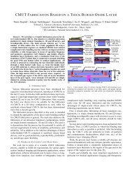
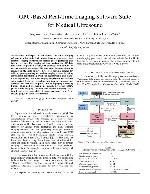
Figure 2. <strong>Real</strong>-time image reconstruction procedure.graphics card (Nvidia, Santa Clara, CA), a Virtex-6 FPGAboard (ML605, Xilinx Inc., San Jose, CA), a Surelite OPO Pluslaser (Continuum, Santa Clara, CA), and a custom-designedinterface PCB. Table I lists relevant specifications of thegraphics card we used in this implementation.As this system aims to be a flexible imaging plat<strong>for</strong>m <strong>for</strong>various types of probes and imaging schemes, it providesmultiple options <strong>for</strong> excitation. To excite the transducers <strong>for</strong>transmit, we can either program the FPGA to control the onchippursers integrated with the CMUT probe, or simply usethe Verasonics pulsers. In photoacoustic imaging mode, theFPGA is programmed to control the laser and synchronize itwith the data acquisition system.The software takes raw RF data collected by the Verasonicsdata acquisition system, and processes them on <strong>GPU</strong> toreconstruct real-time images. Fig. 2 shows the real-time imagereconstruction procedure of this software. Task parallelismbetween the copy engine and the kernel engine of <strong>GPU</strong> wasimplemented using two CUDA streams. While the copy enginetransfers a block of raw data to the <strong>GPU</strong> memory, the kernelengine processes the previous data block <strong>for</strong> analytic signalconversion combined with optional Hadamard decoding andaperture weighting, as depicted in Fig. 3. Delay-and-sumoperations are single instruction multiple data (SIMD)executions, and are thus suitable <strong>for</strong> <strong>GPU</strong> parallel processing.Fig. 4 describes the data-level parallelism implemented <strong>for</strong>delay-and-sum operations. To reconstruct an image with Npixels, M∙N CUDA threads are created and M threads areassigned to each pixel, where M is empirically optimized <strong>for</strong>each imaging application. The threads assigned to adjacentpixels are grouped together in the same thread block tomaximize the memory access efficiency by utilizing the spatialFigure 3. Task parallelism in data transfer and data processing.Figure 4. Data-level parallelism in delay-and-sum operations.locality of the raw data samples stored in the 2-D texturememory.III.REAL-TIME IMAGING SOFTWARE SUITEThe software suite consists of multiple imaging programscustomized <strong>for</strong> different purposes, a real-time RF data analyzer,and a Verasonics transmit controller. The individual programsin the suite are listed and briefly described in Table II.General Imager is the most-general purpose imagingprogram that works with arbitrary probe geometry and variousimaging schemes, including conventional phased arrayimaging, synthetic phased array imaging with and withoutProgramGeneral ImagerRotating Plane ImagerMIP ImagerPA ImagerVolume ImagerFlow ImagerRF AnalyzerTX ControllerDescriptionTABLE IIPROGRAMS IN THE REAL-TIME IMAGING SOFTWARE SUITEThe most general-purpose imaging program displaying three arbitrary cross-sectional imagesA fast real-time imaging program showing one B-mode image rotating about the axis<strong>Software</strong> displaying a rotating B-mode image and its maximum intensity projection (MIP)Photoacoustic and ultrasound dual-mode imaging software<strong>Real</strong>-time volume reconstruction program displaying a volume-rendered image and three cross-sectional images.Ultrafast flow imaging software (under development)A 4-channel real-time RF data analyzerVerasonics transmit controller <strong>for</strong> use in drug delivery and high-intensity focused ultrasound (HIFU) applications
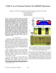
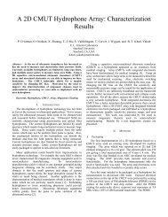
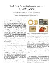
Figure 5. The user interface of a real-time imaging program <strong>for</strong> displaying three cross-sectional images. The shown images are real-time images of ten fishingwires obtained using a 128-element ring CMUT array.Hadamard coding, flash imaging, plane wave compounding,and linear array imaging. Fig. 5 shows the user interface of thisprogram, captured in a real-time imaging experiment using a128-element ring CMUT array with a 4.84-mm radius and a6.5-MHz center frequency.The other imaging programs are derived from this generalpurposeimaging program, and optimized <strong>for</strong> their own specialpurposes. The high computing power of <strong>GPU</strong> enables not onlyfast real-time image reconstruction, but also other computeintensiveoperations <strong>for</strong> effective volume visualization, realtimevolume rendering, and ultrafast Doppler imaging. Forexample, MIP Imager reconstructs one B-mode image rotatingabout the axis by a small angle step from frame to frame, anddisplays its maximum intensity projection (MIP) in real-time[5]. Another imaging program in the suite, Volume Imager,reconstructs the entire volume in real-time, and displays onevolume-rendered image along with three cross-sectionalimages on the screen. PA Imager is a photoacoustic imagingprogram with dual-mode imaging capability <strong>for</strong> bothphotoacoustic and ultrasound imaging [6]. <strong>Imaging</strong> results withsome of these programs are presented in the next section.IV.IMAGING RESULTSFigs. 5-7 show the real-time images from General Imager,MIP Imager, and PA Imager, respectively. These images wereFigure 6. <strong>Real</strong>-time images of metal spring targets from MIP Imagerobtained using (a) a 64-element ring CMUT array and (b) a 128-element ringCMUT array.
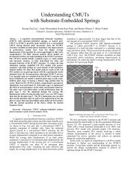
Figure 7. <strong>Real</strong>-time images of a mouse subcutaneous kidney tumor from PA Imager obtained using a 24-element 1-D CMUT array. The vasculature in the tumoris visible in the photoacoustic image.TABLE IIIEXPERIMENTAL CONDITIONS AND IMAGING RATES OF FIGS. 5-7Fig. 5 Fig. 6(a) Fig. 6(b) Fig. 7<strong>Imaging</strong> program General Imager MIP Imager MIP Imager PA ImagerProbe128-element ring CMUT array 64-element ring CMUT array 128-element ring CMUT array 24-element 1-D CMUT array(4.84-mm radius)(1.16-mm radius)(4.84-mm radius)(63-μm pitch)Probe center frequency 6.5 MHz 10 MHz 6.5 MHz 8.5 MHz<strong>Imaging</strong> scheme SPA-HW 1 SPA-HW 1 SPA-HW 1 CPA 2 + Photoacoustic<strong>Imaging</strong> targetTen fluorocarbon fishing wires A metal springA metal spring(150-μm thickness)(6-mm diameter)(13-mm diameter)A mouse subcutaneous tumor<strong>Imaging</strong> depth 25 mm 15 mm 40 mm 15 mm<strong>Imaging</strong> rate100 <strong>for</strong> ultrasound image14 104 11in frames per second10 <strong>for</strong> photoacoustic image 31 SPA-HW: Synthetic phased array imaging with Hadamard coding and aperture weighting (Norton weighting and cosine weighting)2 CPA: Classic phased array imaging3 <strong>Imaging</strong> rate <strong>for</strong> photoacoustic image is limited by the 10-Hz laser repetition rate.obtained using different targets and different probes.Experimental conditions and acquired imaging rates from theseexperiments are summarized in Table III.V. CONCLUSIONWe developed a <strong>GPU</strong>-based ultrasound imaging softwaresuite that is capable of real-time volumetric imaging witharbitrary probe geometries and various imaging schemesincluding non-conventional techniques such as syntheticbeam<strong>for</strong>ming and Hadamard coding. Exploiting massive datalevelparallelism in beam<strong>for</strong>ming operations, this softwaresuccessfully generated volumetric images in real-time <strong>for</strong>various imaging schemes. The real-time imaging wasdemonstrated using our custom CMUT probes with annular,linear, and rectangular shapes.ACKNOWLEDGMENTThis work is funded by the National Institutes of Healthunder Grants HL67647 and CA134720. We also thank Nvidia<strong>for</strong> donating a C2070 graphics card.REFERENCES[1] Ö. Oralkan, A. S. Ergun, J. A. Johnson, U. Demirci, M. Karaman, K.Kaviani, T. H. Lee, and B. T. Khuri-Yakub, “Capacitive micromachinedultrasonic transducers: Next-generation arrays <strong>for</strong> acoustic imaging?,”IEEE Trans. Ultrason., Ferroelect., Freq. Contr., vol. 49, no. 11, pp.1596–1610, Nov. 2002.[2] J. W. Choe, Ö. Oralkan, A. Nikoozadeh, A. Bhuyan, B. C. Lee, M.Gencel, and B. T. Khuri-Yakub, “<strong>Real</strong>-time volumetric imaging system<strong>for</strong> CMUT arrays,” in Proc. IEEE Ultrason. Symp., pp. 1064–1067,2011.[3] J. W. Choe, Ö. Oralkan, A. Nikoozadeh, M. Gencel, D. N. Stephens, M.O’Donnell, D. J. Sahn, and B. T. Khuri-Yakub, "Volumetric real-timeimaging using a CMUT ring array," IEEE Trans. Ultrason., Ferroelect.,Freq. Contr., vol. 59, no. 6, pp. 1201–1211, Jun. 2012.[4] J. Bercoff, G. Montaldo, T. Loupas, D. Savery, F. Mézière, M. Fink, andM. Tanter, “Ultrafast compound Doppler imaging: Providing full bloodflow characterization,” IEEE Trans. Ultrason., Ferroelect., Freq. Contr.,vol. 58, no. 1, pp. 134–147, Jan. 2011.[5] J. W. Choe, A. Nikoozadeh, Ö. Oralkan, and B. T. Khuri-Yakub, "<strong>GPU</strong>basedreal-time volumetric ultrasound image reconstruction <strong>for</strong> a ringarray," IEEE Trans. <strong>Medical</strong> <strong>Imaging</strong>, vol. 32, no. 7, pp. 1258–1264, Jul.2013.[6] A. Nikoozadeh, J. W. Choe, S. Kothapalli, A. Moini, S. S. Sanjani, A.Kamaya, Ö. Oralkan, S. S. Gambhir, and B. T. Khuri-Yakub,“Photoacousitc imaging using a 9F MicroLinear CMUT ICE catheter,”presented at the IEEE Ultrason. Symp., Dresden, Germany, Oct. 7-10,2012.