Understanding CMUTs with Substrate-Embedded Springs
Understanding CMUTs with Substrate-Embedded Springs
Understanding CMUTs with Substrate-Embedded Springs
- No tags were found...

Create successful ePaper yourself
Turn your PDF publications into a flip-book with our unique Google optimized e-Paper software.
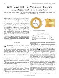
<strong>Understanding</strong> <strong>CMUTs</strong><strong>with</strong> <strong>Substrate</strong>-<strong>Embedded</strong> <strong>Springs</strong>Byung Chul Lee * , Amin Nikoozadeh, Kwan-Kyu Park, and Butrus (Pierre) T. Khuri-YakubEdward L. Ginzton Laboratory, Stanford University, Stanford, CA* bclee79@stanford.eduAbstract — A capacitive micromachined ultrasonic transducer(CMUT) <strong>with</strong> substrate-embedded springs, as named post-CMUT or PCMUT, provides many benefits over a conventionalCMUT having flexural plate movement. Since the P<strong>CMUTs</strong>tructure resembles an ideal piston transducer, the improvementsin performance mainly stem from the higher averagedisplacement of the top plate for a given gap height. In this work,comprehensive 3-D finite element analysis (FEA) models aredeveloped to further our understanding of the PCMUT structure.The 3-D FEA models include 3 analysis types, i.e. static, modal,and harmonic analyses, to fully understand the static anddynamic behavior of the PCMUT structure. To reduce the longsimulation runtime, simplified 3-D FEA models <strong>with</strong> quartersymmetry and ideal springs are used instead of full transducerelement models. We show that modal analysis results of the 3-DFEA models are in good agreement <strong>with</strong> the experimental resultsobtained from the first-generation fabricated PCMUT devices.Two top plate types are considered for the PCMUT structure andhence included in our model: a uniform plate (type 1) and a nonuniformplate (type 2) having a thinner edge portion than itscenter. Based on the 3-D FEA models, comprehensive parametricsimulations were performed for both plate types to understandthe effect of each parameter on the static and dynamic behavior.The plate type 2 provided better overall performance than theplate type 1. For the simulated designs the average DCdisplacement achieved using the plate type 2 was over 50% largerthan that for the plate type 1. The FEA simulations also revealedthat careful attention must be paid to the engineering of the topplate to assure that unwanted higher plate modes do not interfere<strong>with</strong> the normal operation of the device <strong>with</strong>in the desiredfrequency band.Keywords- Ultrasound; CMUT; substrate-embedded springs;piston transducer; finite element analysis (FEA)I. INTRODUCTIONA capacitive micromachined ultrasonic transducer (CMUT)<strong>with</strong> ideal piston-like plate motion provides many benefits overa conventional CMUT having flexural plate movement [1][2].As shown in Fig. 1(a) and 1(b), a conventional CMUT istypically composed of multiple cells. Since the anchoredregions present in a conventional CMUT structure, the fillfactor is less than one, which translates to an inevitable loss inaverage displacement compared to an ideal piston transducer.While the average plate displacement of an ideal pistontransducer is equivalent to its maximum plate displacement, theaverage displacement of the moving part of a conventionalCMUT is typically one third of its maximum platedisplacement (Fig. 1(b)). Assuming the same effective gapheight, the average displacement of an ideal electrostatic pistontransducer is approximately 2.6 times larger than that of themoving part of a conventional CMUT [2][3].Our proposed CMUT structure <strong>with</strong> substrate-embeddedsprings is called post-CMUT or PCMUT because it iscomposed of a rigid top plate connected to a substrate usinglong and narrow posts. The posts provide the spring constant ofthe structure rather than the top plate as in a conventionalCMUT (Fig. 1(c)). The PCMUT structure resembles an idealelectrostatic piston transducer, promising improvements inperformance by achieving higher average displacement of thetop plate for a given gap height.One Cell(a)AnchoredRegionPost<strong>Springs</strong>Plate<strong>Substrate</strong>Plate1.0~ 0.41 ~ 0.13<strong>Substrate</strong>(c)Figure 1. Schematic drawings of (a) a conventional CMUT array, (b) aCMUT cell, and (c) a PCMUT structureWe have previously reported on the PCMUT structure anddemonstrated the functionality of the first generation fabricateddevices [2]. We measured a peak-to-peak pressure of over1MPa <strong>with</strong> a broad fractional bandwidth of over 100%. Ourprevious FEA model only included simple 2-D structures.Therefore, more complex FEA models involving a wholeelement representation of the device is desired to betterunderstand the device operation and achieve an optimumdesign for a particular application.In this work, we report on comprehensive 3-D FEA modelsdeveloped to further our understanding of the P<strong>CMUTs</strong>tructure. Using these models and the knowledge gained, wepresent the design considerations required to achieve anoptimum design for the PCMUT structure.(b)
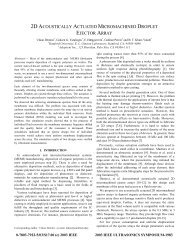
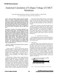
II. METHODSA. 3-D Finite Element Analysis (FEA) ModelWe constructed a 3-D FEA full transducer element modelas close to a realistic model as possible in order to understandthe effect of each parameter on the static and dynamic behaviorof the PCMUT structure. We used a commercial tool, ANSYS,Inc. This full transducer element model includes three analysistypes: static, modal, and harmonic analyses. In the staticanalysis, the displacement of the top plate can be simulated fora given DC bias voltage. Additionally, the pull-in voltage of thestructure can be automatically calculated. The ideality of thePCMUT structure is also evaluated by the ratio between theaverage and maximum displacement in the static mode. In themodal analysis, the fundamental and higher harmonicfrequencies of a PCMUT structure can be solved for. In theharmonic analysis, an average acoustic pressure spectrum as afunction of frequency can be obtained. To realize a practicaldevice, the top plate should provide a complete encapsulationto preserve the vacuum gap, which can be accomplished byanchoring the top plate at the transducer plate edges. Wespecified two types of top plate: a uniform plate (type 1, Fig.2(a)) and a non-uniform plate (type 2, Fig. 2(b)) having athinner edge portion than its center. Due to several resourcelimitations, such as large number of nodes, long computationtime, and limited node and element counts, a simplified 3-DFEA model was constructed. This simplified model assumes asquare 2-D array element and it uses a quarter symmetricmodel for the PCMUT structure and the medium (Fig. 2(c)).The actual posts were also replaced <strong>with</strong> an ideal springelements in the simplified model.differences. The error of the average and maximumdisplacement between them is less than 5%. Thus, thesimplified model using the ideal spring elements seems torepresent the actual model well.We used laser doppler vibrometery (LDV) to validate themodal analysis results of the simplified 3-D FEA. It is seenfrom Fig. 3 that the simulated mode shapes of plate types 1 and2 show a good agreement <strong>with</strong> the measurement results. Thefirst mode shape shown for plate type 2 in Fig. 3 is caused bythe structural asymmetry due to the electrical connection bridge,which is correctly revealed in the simulation.SimulatedModeMeasuredModePlate Type 1 Plate Type 2Figure 3. Simulated mode shapes vs. LDV measurementsfor plate types 1 and 2.-26.7nm 0.404nm -22.7nm 11.7pm(a)(b)Figure 4. Static analysis results of plate (a) type 1 and (b) type 2.(a)(b)(c)Figure 2. Schematic illustrations of two PCMUT top plate types:(a) type 1 and (b) type 2. (c) Schematic demonstration of the simplified3-D FEA model of a PCMUT.B. Simplified 3-D FEA Model VerificationIn order to use the simplified 3-D FEA model instead of afull 3-D FEA transducer element model, it is necessary tocompare the simulation results of each model to verify thevalidity of the simplified model. First, we used FEA toseparately model a single post and extract its spring constant.We calculated the error between the values obtained using thetheoretical expression for the spring constant and those of FEAsimulation results. We confirmed that the error is less than0.5%. Then, the full 3-D model of a transducer element usesideal springs <strong>with</strong> the extracted spring constant in place of theactual posts. The static simulation results between thestructures using actual and ideal posts showed minorC. Analysis of PCMUT StructuresFigure 4 shows the static analysis results for two PCMUTdesigns, which only differ in their plate types (i.e., one usesplate type 1 and the other plate type 2). For plate type 1 design,the ratio of average to maximum displacement is 0.41, which isclose to the conventional CMUT. On the other hand, bymaking the edge of the top plate thin, as in the plate type 2, theratio of average to maximum displacement is 0.83, which iscloser to the ideal piston transducer. Both the simulations weredone at a DC bias equal to 80% of the pull-in voltage for theircorresponding design. It is seen from these simulations that theaverage displacement of the plate type 2 design isapproximately twice that of the plate type 1 design.From the static analysis, we found that the plate type 2provides better overall performance than the plate type 1.Based on this finding, we started to design a PCMUT structureusing plate type 2 for a particular application. We targeted a 2-D array element <strong>with</strong> a center frequency of about 3.2MHz.Assuming a λ/2 element pitch criterion at the center frequency,a width of 240μm was determined for the width of the PCMUTelement size. Also a fractional bandwidth of about 100% ormore was considered as a design target. The physicalparameters of a PCMUT design targeting the abovespecifications are listed in Table 1.
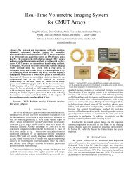
TABLE 1. Simulation Parameters of PCMUTPARAMETERVALUENumber of cells in one element 1Top plate width (μm) 200Top plate thickness (μm) 9Top plate materialSiBottom plate width (μm) * 240 *Bottom plate thickness (μm) 1Bottom plate materialSiClamp edge width (μm) 10Effective gap height (μm) 0.15Number of posts 25Post pitch (μm) 40Post diameter (μm) 5Post height (μm) 50* λ/2 at 3.2 MHz (for phased array)Magnitude (kPa/V)Higher ModeInterferenceD. Design Consideration of PCMUTIn order to eliminate the undesired dip in the frequencyband of interest, the higher mode interference should be outsidethis range. To this extent, modal analyses were performed <strong>with</strong>comprehensive parametric changes of the top plate toinvestigate their effect on this higher mode. Even though notshown here, we observed in our simulations that this undesiredmode frequency is mostly a function of the top plateengineering and it is not significantly affected by the existenceof the posts. Therefore, for the following modal analyses, onlythe top plate <strong>with</strong>out any posts was simulated.First, the Young’s modulus of the top plate was modified.As shown in Fig. 6(a), the undesired mode frequency increaseswhen the top plate is stiffer. Choosing an arbitrary Young’smodulus that is 100 times that of silicon, we were able toeliminate the unwanted dip in the frequency band of interestand achieve a wide fractional bandwidth of 132% (Fig. 6(b)).This arbitrarily large and maybe unrealistic Young’s moduluswas primarily chosen to verify that our hypothesis regardingthe source of the unwanted dip is indeed valid.Frequency(a)Frequency (MHz)Fundamental Mode (F-mode)Undesired Mode (U-mode)Normalized Young’s Modulus (N = E/E si )(a)5898 47427 -34968 62107(b)(c)Figure 5. (a) The average acoustic pressure spectrum of the designedPCMUT structure. Modal analysis results of the designed PCMUT structure:(b) Fundamental mode and (c) first undesired higher mode.Figure 5(a) shows the harmonic analysis result of thedesigned PCMUT structure. The graph represents an averageacoustic pressure over the transducer surface as a function offrequency. As it is seen from this figure, an undesired dip ispresent in the middle of the frequency band of interest. It turnsout that this dip arises from the higher mode interference,which is verified by the modal analysis of the P<strong>CMUTs</strong>tructure. Figure 5(b) and 5(c) show the fundamental and thefirst symmetric harmonic mode shapes of the structure invacuum. As it is illustrated in these figures, the top platedisplacement is in phase at the fundamental frequency of5.52MHz. However, at the first symmetric harmonic frequencyof 6.46MHz, the center and the corners of the top plate are outof phase, resulting in destructive interference. The differencebetween the fundamental frequency and this undesiredharmonic frequency is so close resulting in the appearance ofthe unwanted dip in the frequency band of interest.Magnitude (kPa/V)f c = 6.51 MHz-3 dB FBW = 132 %Peak = 23.96kPa/VFrequencyE = E siE = 100 × E si(b)Figure 6. (a) Fundamental and undesired mode frequencies as a functionof normalized Young’s modulus of the top plate. (b) Average acousticpressure spectrum showing the effect of large Young’s modulus.There are other ways to achieve a stiffer top plate. Themodification of the thickness of the top plate was considerednext. As shown in Fig. 7(a), the undesired mode frequencyincreases when the top plate is thicker. However, a largerthickness contributes to a larger mass so that the fundamentalfrequency decreases at the same time. We also looked at theeffect of shrinking the whole top plate geometry in alldimensions, as seen in Fig. 7(b). In this figure, a “Scaling
TABLE 2. Simulation Parameters of modified PCMUTFrequency (MHz)F-modeU-modeRatioTop Plate Thickness (μm)(a)Ratio (= U-mode/F-mode)PARAMETERVALUENumber of cells in one element 4Top plate width (μm) 100Top plate thickness (μm) 20Top plate materialSiBottom plate width (μm) * 120 *Bottom plate thickness (μm) 0.2Bottom plate materialSiClamp edge width (μm) 5Effective gap height (μm) 0.15Number of posts 9Post pitch (μm) 30Post diameter (μm) 5Post height (μm) 50* λ/4 at 3.2 MHzFrequency (MHz)F-modeU-modeRatioRatio (= U-mode/F-mode)Magnitude (kPa/V)Higher ModeInterferenceScaling Factor(b)Figure 7. Fundamental and undesired mode frequencies as a function of(a) top plate thickness and (b) scaling factorFactor” of two, for example, means that all the dimensions (e.g.,thickness, width, etc.) of the top plate are linearly shrunk by afactor of two. The fundamental and undesired modefrequencies both linearly increase when the dimensions of thetop plate is scaled down.III. RESULTS AND DISCUSSIONSUsing the knowledge gained in the previous section, wedesigned a new top plate <strong>with</strong> its specific dimensions listed inTable 2. In this new design, we mainly scaled the top plate by afactor of 0.5 and also increased the thickness of the top plate toeliminate the higher mode interference, as shown in Fig. 8.However, in this new design, one element is composed of fourcells instead of one cell to maintain the same 240μm elementpitch. The sharp dip seen in the red plot of Fig. 8, arises fromthe mutual interaction among cells, which is a well-knownphenomenon in conventional CMUT. However, since ANSYSdoes not take the viscosity of the medium into account inharmonic simulations, this effect may have been unrealisticallyexaggerated in this simulation. Ignoring this sharp dip, thefractional bandwidth of this new PCMUT design isapproximately 100 % around the center frequency of 4.3MHz.Also, the maximum peak pressure is 26.5kPa/V at a frequencyof 2.6MHz. All these simulations were performed <strong>with</strong> a DCbias of 59.5V, which is 80 % of the pull-in voltage.FrequencyFigure 8. The average acoustic pressure spectrum ofthe second PCMUT design in table 2.I. CONCLUSIONS AND FUTURE WORKSWe developed a comprehensive 3-D FEA model for thePCMUT structure. Using this model we demonstrated thatcareful engineering of the top plate is essential in achieving thedesired response. In particular, the first harmonic frequency ofthe top plate should be outside the frequency band of interest toavoid undesired interference.Based on the simulation results presented here, we will startthe fabrication of the second-generation PCMUT devices in thenear future.ACKNOWLEDGMENTThis work was supported by the National Institutes ofHealth (NIH) under grant 5R01CA134720. We fabricated thePCMUT devices at the Stanford Nanofabrication Facility(Stanford, CA), a member of National NanotechnologyInfrastructure Network. We would like to thank Paul Cristmanand Polytec, Inc. for the LDV measurements.REFERENCES[1] Y. Huang, X. Zhuang, E. O. Hæggstrom, A. S. Ergun, C. H. Cheng, andB. T. Khuri-Yakub, “CMUT <strong>with</strong> piston-shaped membranes: Fabricationand experimental characterization,” IEEE Trans. Ultrason., Ferroelect.,Freq. Contr., vol. 56, no. 1, pp. 136–145, 2009.[2] A. Nikoozadeh and B. T. Khuri-Yakub, “CMUT <strong>with</strong> substrateembeddedsprings for non-flexural plate movement,” in Proc. IEEEUltrason. Symp., San Diego, USA, pp. 1510–1513, Oct. 2010.[3] A. Lohfink and P.-C. Eccardt, “Linear and nonlinear equivalent circuitmodeling of <strong>CMUTs</strong>,” IEEE Trans. Ultrason., Ferroelect., Freq. Contr.,vol. 52, no. 12, pp. 2163–2172, 2005.