A 2D CMUT Hydrophone Array: Characterization Results
A 2D CMUT Hydrophone Array: Characterization Results
A 2D CMUT Hydrophone Array: Characterization Results
- No tags were found...

Create successful ePaper yourself
Turn your PDF publications into a flip-book with our unique Google optimized e-Paper software.
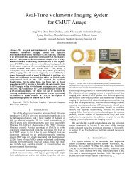
A <strong>2D</strong> <strong>CMUT</strong> <strong>Hydrophone</strong> <strong>Array</strong>: <strong>Characterization</strong><strong>Results</strong>P. Cristman, O. Oralkan, X. Zhuang, T.-J. Ma, S. Vaithilingam, T. Carver, I. Wygant, and B. T. Khuri-YakubE. L. Ginzton LaboratoryStanford UniversityStanford, CA, USAKhuri-yakub@stanford.eduAbstract— As the use of ultrasonic transducers has increased sohas the need to measure and characterize their pressure fields.Currently available hydrophones are limited by long scan times,and multiple source pulses to measure large area fields. Using a<strong>2D</strong> capacitive micro-machined ultrasonic transducer (<strong>CMUT</strong>)array and associated electronics we are able to improve on theselimitations. The <strong>CMUT</strong> inherently allows for a tunablesensitivity by changing DC bias. Motivated by the need toimprove the characterization of megasonic cleaners used insemiconductor processing we were able to implement such anarea hydrophone.Keywords: <strong>Hydrophone</strong>, <strong>CMUT</strong>, <strong>Array</strong>, Megasonic CleaningI. INTRODUCTIONThe development of hydrophone technology has not beenas fast as the increase in ultrasound applications. Yet to ensuresafety the ultrasound pressure field needs to be characterizedand measured before widespread use. Ultrasound fields arecurrently characterized using piezoelectric and optical fiberhydrophones. The current hydrophones are limited by smallapertures which require long mechanical scans to measure largefields. These scans require multiple pulses from the samesource which may not be uniform from pulse to pulse. Also,the mechanical motion of the hydrophone can disturb themedium and thus the field pattern that is being measured.Current hydrophones are also limited by fixed sensitivity anddynamic pressure range. Lastly current hydrophones are noteasily packaged to operate in non-ideal environments.Many applications could benefit from improvements inhydrophone technology. For example the sonic field is almostnever characterized for megasonic cleaning equipment used insemiconductor manufacturing. In semiconductormanufacturing yield is critical so any damage generated duringmegasonic cleaning can be extremely costly. One majorobstacle is that the small aperture and shape of currenthydrophones cannot mimic the large disruption caused by thewafer or mask being cleaned. Another application is thecharacterization of medical transducers which is done in watertanks which do not perfectly match tissue [1]. Embeddinghydrophones in tissue mimicking phantoms could providebetter characterization. Measuring lithotripsy equipmentsuffers greatly from the pulse to pulse variation of theultrasound source [2].Using a capacitive micro-machined ultrasonic transducer(<strong>CMUT</strong>) as a hydrophone appeared as an extension frommedical imaging. <strong>Array</strong> <strong>CMUT</strong>s with integrated electronicshave been demonstrated for medical imaging [3]. Using anarray architecture allows large areas to be measured without theneed for mechanical scanning. Also, electronic switchingmeans no motion artifacts are present during the area scan. Bychanging the DC bias on the <strong>CMUT</strong> the sensitivity andmeasureable pressure range can be tuned for the application ofinterest. <strong>CMUT</strong>s are inherently broadband and the bandwidthcan be further increased with conventional and collapse modeoperations. For all the above reasons the <strong>CMUT</strong> should makea very versatile hydrophone. With integrated electronics the<strong>CMUT</strong> has a better minimum detectable pressure than currenthydrophones. Here a <strong>2D</strong> <strong>CMUT</strong> array with integrated frontendelectronics has been packaged, and calibrated as a hydrophoneto demonstrate tunable sensitivity, pressure range, and areameasurement. This work was motivated by the need tomeasure megasonic cleaners used in semiconductormanufacturing. <strong>Results</strong> for a test megasonic cleaner arepresented.II.METHODSA. PackagingThe first implementation of a <strong>2D</strong> hydrophone based on a<strong>CMUT</strong> array used an existing array developed for medicalimaging. The array which was reported on in [3] had 256element arranged in a 16 x 16 grid. The element pitch was 250μm giving a total measurement area of 4 mm x 4 mm. Thearray was flip chip bonded to an ASIC developed for medicalimaging. The ASIC provides both transmit and receivefunctionality. For the hydrophone measurements only thereceive functionality was used. The array and electronics werethen attached and wire bonded to a ceramic chip carrier.Next the array needed to be packaged as a hydrophone formeasurements in de-ionized (DI) water. Exposed electricalconnections on the top of the <strong>CMUT</strong> were protected by coatinga 100 μm thick layer of Polydimethylsiloxane (PDMS) on thesurface of the <strong>CMUT</strong> and chip carrier. After the PDMScoating the pulse-echo device response was maximum at 3.4MHz with a 103% 6-dB fractional bandwidth. The PDMS
III. RESULTSThe sensitivity of the <strong>CMUT</strong> array can be tuned withchanging DC bias as demonstrated during the calibration. Thetunable sensitivity led to a tunable dynamic range. Themaximum and minimum pressure ranges were set by theamplifier saturation and electronic noise, respectively. Theoutput voltage of the <strong>CMUT</strong> hydrophone saturates due toamplifier saturation in the imaging electronics. By changingthe DC bias the measurable pressure range of the devicechanges (Fig. 3). The sensitivity changed from 1 to 76 μV/Pawith a DC bias ranging from 0.95 to 30.85 V (Fig. 4). Thisarray had a minimum detectable pressure of 1.8 mPa/√Hz atFigure 1. Diagram and picture of hydrophone package.coated device was then bonded to an aluminum plate andhousing. A read out cable was built as well. Fig. 1 shows aschematic of the transducer housing and an optical picture.B. CalibrationThe final preparation was to calibrate the array. Tocalibrate the <strong>CMUT</strong> a 2.25 MHz unfocused ultrasoundtransducer (Model: A306S-SU, Olympus-NDT Inc., Waltham,MA) driven at 1.86 MHz was used as a reference source. Thefrequency of 1.86 MHz was chosen for the application ofcharacterizing megasonic cleaning equipment. The referencesource was then measured with a commercial calibratedhydrophone (Model: <strong>Hydrophone</strong> HNP-0400 Pre-AmplifierAH 2010, Onda Corp., Sunnyvale, CA) at S = 1 to find thepeak pressure output at this distance. The commercialhydrophone gave a mapping of input voltage of the referencesource to the output pressure at S = 1.Next the <strong>CMUT</strong> array was positioned over the samereference source at the same height and the output voltage ofthe <strong>CMUT</strong> was measured. Using a mechanical stage all 256elements in the <strong>CMUT</strong> array were stepped to the same locationabove the reference source. By stepping to the same locationthe output voltage from each element was found for a giveninput pressure to the element. Knowing both values, outputvoltage and input pressure, a calibration look up table could begenerated in units of V/Pa. The raw output voltage was thendivided by the calibration data to produce a calibrated image ofthe acoustic field.To test the calibration the reference source wasmechanically scanned using the commercial hydrophone toobtain a reference beam profile. The mechanically scannedpressure field by the commercial hydrophone and theelectronically scanned pressure field by the <strong>CMUT</strong> array areshown in Fig. 2. The lack of mechanical scanning did increasethe speed of data acquisition. Also, by having no mechanicalscanning there was no disruption of the measurement fluid.Thus another potential error source produced by the motion ofthe hydrophone in the medium was eliminated.Figure 2. Mechanically scanned calibrated image (Top). Electrically scanned<strong>CMUT</strong> hydrophone image (Bottom)
Figure 5. Spot Shower measured at 5 W of input power.Figure 3. <strong>CMUT</strong> response as a function of input pressure and <strong>CMUT</strong> DCbias voltage. Linear fit to find sensitivity of device.Figure 4. <strong>CMUT</strong> sensitivity as a function of DC bias.30.85 V DC bias. The maximum detectable pressure for the<strong>CMUT</strong> array was 800 kPa peak to peak at 0.95 V DC bias.The peak pressure was measured at the 1-dB compression ofoutput voltage due to the amplifier saturation. Some DC bias isnecessary to obtain a good measurement. The minimum andmaximum pressures both span two orders of magnitude withDC bias varying form less than 10 % to more than 90 % of thecollapse voltage.The <strong>CMUT</strong> hydrophone was used to measure the acousticfield in a commercially available megasonic cleaner (Model:Spot Shower, Kaijo Corp., Tokyo, Japan). The Spot Showersystem operates at a frequency of 0.95 MHz. The calibrationprocedure described above was repeated at 0.95 MHz beforemeasuring the Spot Shower. Measuring the field with astandard hydrophone is difficult and not representative of thesurface of a wafer or mask. The Spot Shower system producesa circular jet of cleaning solution in this case DI water with asonic field in the jet. The field from the Spot Shower is shownin Fig. 5 and was measured at 5 W of input power and adistance of 10 mm from the nozzle head. Measurements atdifferent power levels and distances gave consistent resultssuggesting a circular source. Since a medical imagingtransducer designed to measure low pressure was used in thefirst implementation, it was difficult to measure the highpressure fields used in megasonic cleaning due to amplifiersaturation.IV. CONCLUSIONIt was shown in this work that the <strong>CMUT</strong> has beensuccessfully implemented as a <strong>2D</strong> tunable hydrophone. A widerange of sensitivities from 1 to 76 μV/Pa was demonstrated.Also an excellent minimum detectable pressure of 1.8mPa/√Hz was measured. The array measured a 4 mm x 4 mmarea with no mechanical scanning. The array was used tomeasure a megasonic cleaner which would be difficult with acommercial hydrophone.Operating the <strong>CMUT</strong> array in receive only mode allows forgreater flexibility in front end electronics design. Removingthe transmit function from the electronics gives more space foroutput amplifier design. The output amplifier can be madewith variable gain to further improve the measurable range ofpressures and frequencies of the <strong>CMUT</strong>. The packagingflexibility of the <strong>CMUT</strong> array will allow the hydrophone tocorrectly match the boundary conditions in the desiredapplication. This is critical in the characterization ofmegasonic cleaners where the presence of the wafer cansignificantly impact the pressure field. Several such arrayscould be positioned on a silicon wafer to measure the pressurefield across the entire wafer with nearly identical boundary
conditions as the real wafers. By adjusting the DC bias of the<strong>CMUT</strong> the sensitivity of the hydrophone array can beoptimized for the pressure range of interest. The <strong>CMUT</strong> arraycan measure a wide range of pressures and frequencies. The<strong>CMUT</strong> makes a perfect candidate for measuring area pressuredistributions without mechanical scanning. The number ofelements, element size, element frequency, and elementsensitivity can all be optimized for high sensitivity andbandwidth for the desired application. The initial results fromthis first implementation are promising for <strong>CMUT</strong> arrayhydrophones.ACKNOWLEDGMENTThis work was supported by the Intel Corporation SantaClara, CA, USA 95054.REFERENCES[1] R Finney, M Halliwell, S F Mishriki, and A C Baker “Measurement oflithotripsy pulses through biological media,” Physics in Medicine andBiology, Vol. 36, pp 1485-1493, Nov. 1991.[2] Y. A. Pishchalnikov, J. A. McAteer, R. J. VonDerHaar, I. V.Pishchalnikova, J. C. Williams Jr., A. P. Evan, “Detection of significantvariation in acoustic output of an electromagnetic lithotriptor,” TheJournal of Urology, Vol.176, Issue 5, pp. 2294-2298 Nov. 2006,.[3] I. Wygant, X. Zhuang, D. Yeh, Ö. Oralkan, A. S. Ergun, M. Karaman,and B. T. Khuri-Yakub, "Integration of <strong>2D</strong> <strong>CMUT</strong> arrays with front-endelectronics for volumetric ultrasound imaging," Ultrasonics,Ferroelectrics and Frequency Control, IEEE Transactions on, vol. 55,no. 2, pp. 327-342, Feb. 2008.