Dynamic FEM analysis of multiple cmut cells in immersion ...
Dynamic FEM analysis of multiple cmut cells in immersion ...
Dynamic FEM analysis of multiple cmut cells in immersion ...
- No tags were found...

Create successful ePaper yourself
Turn your PDF publications into a flip-book with our unique Google optimized e-Paper software.
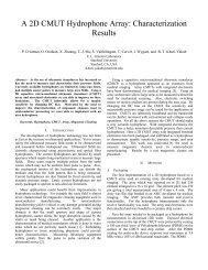
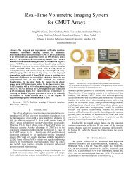
2004 IEEE Ultrasonics SymposiumDYNAMIC <strong>FEM</strong> ANALYSIS OF MULTIPLE CMUT CELLS IN IMMERSIONBaris Bayram, Goksen G. Yaralioglu, Arif Sanli Ergun, Ömer Oralkan, and Butrus T. Khuri-YakubEdward L. G<strong>in</strong>zton Laboratory, Stanford University, Stanford, CA 94305-4088Abstract – This paper reports on the accurate model<strong>in</strong>g <strong>of</strong><strong>immersion</strong> capacitive micromach<strong>in</strong>ed ultrasonic transducers(cMUTs) us<strong>in</strong>g the time-doma<strong>in</strong>, nonl<strong>in</strong>ear f<strong>in</strong>ite elementpackage, LS-DYNA, developed by Livermore S<strong>of</strong>twareTechnology Corporation (LSTC). A capacitivemicromach<strong>in</strong>ed ultrasonic transducer consists <strong>of</strong> many cMUT<strong>cells</strong>. In this paper, a square membrane was used as the unitcell to cover the transducer area by periodic replication onthe surface. The silicon membrane, silicon oxide post and<strong>in</strong>sulation layer were modeled, and the contact region wasdef<strong>in</strong>ed on the membrane and the substrate surfaces. The 3-Df<strong>in</strong>ite element model also <strong>in</strong>cluded a 500 µm-thick substrateand the acoustic fluid medium, to take <strong>in</strong>to account two ma<strong>in</strong>sources <strong>of</strong> coupl<strong>in</strong>g <strong>in</strong> cMUTs: Scholte wave propagat<strong>in</strong>g atthe solid-fluid <strong>in</strong>terface and Lamb wave propagat<strong>in</strong>g <strong>in</strong> thesubstrate. A highly efficient perfectly matched layer (PML)absorb<strong>in</strong>g boundary condition was designed for the acousticmedium to truncate the computational doma<strong>in</strong>. The cMUTwas biased <strong>in</strong>-collapse or out-<strong>of</strong>-collapse with an appliedpotential difference between the membrane and substrateelectrodes: a rectangular pulse excitation was then used forthe conventional, collapsed or collapse-snapback operations<strong>of</strong> the cMUT. Collapsed operation <strong>of</strong> the cMUT generated sixtimes greater acoustic output pressure (641 kPa) than theconventional operation (107 kPa) at both the same biasvoltage (83 V) and the pulse amplitude (+5 V). The vacuumback<strong>in</strong>g and impedance-matched back<strong>in</strong>g were compared todeterm<strong>in</strong>e the <strong>in</strong>fluence <strong>of</strong> wave reflections from the bottom<strong>of</strong> the substrate <strong>in</strong> the collapsed operation. The dynamic <strong>FEM</strong>results were compared to the experimental results forconventional and collapse-snapback operations by apply<strong>in</strong>gstep voltages on biased cMUT membranes. The acousticoutput pressure measurements <strong>of</strong> the cMUT were performedwith a hydrophone. The hydrophone calibration data wasused to f<strong>in</strong>d the sensed pressure. Tak<strong>in</strong>g the attenuation anddiffraction losses <strong>in</strong>to account, the pressure on the cMUTsurface was extracted. The cMUT generated 348 kPa and1040 kPa <strong>in</strong> the conventional and collapse-snapbackoperations, respectively, and good agreement was observedwith the dynamic <strong>FEM</strong> results.I. INTRODUCTIONCapacitive micromach<strong>in</strong>ed ultrasonic transducers (cMUTs)emerged as an alternative to piezoelectric transducers <strong>in</strong>ultrasonic applications [1-4]. A new operation regime, collapsedoperation, was proposed for the cMUTs [5]. Based on static <strong>FEM</strong>calculations, the collapsed operation provided coupl<strong>in</strong>g efficiency(k T 2 ) greater than 0.7, when the cMUT was <strong>in</strong>itially collapsed byapply<strong>in</strong>g a voltage higher than the collapse voltage, and thenbiased between the collapse and snapback voltages [5].Experimental characterization <strong>of</strong> cMUTs operat<strong>in</strong>g <strong>in</strong> thecollapsed regime verified the <strong>FEM</strong> calculations [6]. Recently, anew operation regime, collapse-snapback operation, wasproposed to achieve high acoustic output pressure when thecMUT was operated <strong>in</strong> and out-<strong>of</strong> collapse [7]. The static anddynamic f<strong>in</strong>ite element calculations were <strong>in</strong> good agreement withthe experimental measurements [7].The design <strong>of</strong> cMUTs for collapsed and collapse-snapbackoperations required nonl<strong>in</strong>ear f<strong>in</strong>ite element <strong>analysis</strong>, which<strong>in</strong>cluded the contact dynamics. This paper presents our capabilityto perform fast and accurate FEA to design the cMUTs for bothl<strong>in</strong>ear and nonl<strong>in</strong>ear operations us<strong>in</strong>g LS-DYNA [8], whichfeatures an explicit solver and extended contact and materialtypes to perform the crashworth<strong>in</strong>ess <strong>analysis</strong> [9].II. FINITE ELEMENT CALCULATIONSF<strong>in</strong>ite element methods (<strong>FEM</strong>) were used to analyze the cMUTus<strong>in</strong>g a commercially available <strong>FEM</strong> package (LS-DYNA 970)[8]. The <strong>FEM</strong> model <strong>of</strong> an immersed one-quarter <strong>of</strong> a squarecMUT cell is shown <strong>in</strong> Fig. 1. Symmetry boundary conditionswere applied to cover the transducer area by periodic replication(Fig. 1). The silicon membrane was supported on the edges withsilicon oxide posts. There was a vacuum gap between themembrane and the substrate, which attracted each other, due tothe applied voltages on the electrodes def<strong>in</strong>ed on the bottom <strong>of</strong>the membrane and on the top <strong>of</strong> the substrate with full coverage.The electrodes were assumed to be <strong>in</strong>f<strong>in</strong>itesimally th<strong>in</strong>. A th<strong>in</strong><strong>in</strong>sulation layer <strong>of</strong> silicon oxide over the highly doped siliconsubstrate prevented short<strong>in</strong>g the ground and the membraneelectrodes <strong>in</strong> collapse. Contact surfaces were def<strong>in</strong>ed on thebottom <strong>of</strong> the membrane and on the top <strong>of</strong> the <strong>in</strong>sulation layer tomodel the collapse <strong>of</strong> the membrane. The 3-D f<strong>in</strong>ite elementmodel also <strong>in</strong>cluded a 500 µm-thick substrate and the acousticfluid medium. A highly efficient perfectly matched layer (PML)absorb<strong>in</strong>g boundary condition was designed for the acousticmedium to truncate the computational doma<strong>in</strong> [10]. The physicaldimensions <strong>of</strong> the cMUT used <strong>in</strong> the calculations are given <strong>in</strong>Table I.TABLE IPHYSICAL DIMENSIONS OF THE 2-D cMUTSide length (L) (µm) 30Membrane thickness (T) (µm) 1.2Gap thickness (G) (µm) 0.18Insulat<strong>in</strong>g layer thickness (I) (µm) 0.10Cell periodicity (C) (µm) 35Substrate (S) (µm) 5000-7803-8412-1/04/$20.00 (c)2004 IEEE.2522004 IEEE International Ultrasonics, Ferroelectrics,and Frequency Control Jo<strong>in</strong>t 50th Anniversary Conference
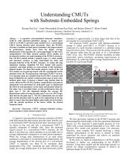
2004 IEEE Ultrasonics Symposiuma)Figure 1. The cMUT simulation modelThe center frequency <strong>of</strong> the unbiased membrane was 10 MHz<strong>in</strong> water. This cMUT design featured collapse and snapbackvoltages <strong>of</strong> 96 V and 70 V, respectively.Prior to the dynamic <strong>analysis</strong>, the cMUT cell was staticallybiased at a voltage us<strong>in</strong>g the dynamic relaxation [9] with<strong>in</strong> the<strong>in</strong>tended operation regime. A pulse was subsequently applied todeterm<strong>in</strong>e the acoustic output pressure.III. RESULTSThe cMUT cell was biased at 83 V both <strong>in</strong> the conventionaland <strong>in</strong> the collapsed operation regimes. Impedance-matchedback<strong>in</strong>g <strong>of</strong> the substrate was assumed <strong>in</strong> this calculation. A +5V,20 ns pulse was then applied, and the acoustic output pressure, 60µm away from the cMUT surface, was calculated (Fig. 2(a)).Conventional and collapsed operations generated 107 kPa and641 kPa, respectively. The frequency spectrum <strong>of</strong> the pressurewas corrected for the spectrum <strong>of</strong> the pulse (Fig. 2(c)). The centerfrequencies were 9.2 MHz (130% BW) <strong>in</strong> the conventionaloperation and 21.6 MHz (108% BW) <strong>in</strong> the collapsed operation.Then the pulse was <strong>in</strong>creased to +30 V (Fig. 2(b)). Conventionaland collapsed operations generated 770 kPa and 4260 kPa,respectively. The center frequencies were 8.6 MHz (132% BW)<strong>in</strong> the conventional operation and 22.7 MHz (84% BW) <strong>in</strong> thecollapsed operation.The impedance-matched back<strong>in</strong>g <strong>of</strong> the substrate is comparedto vacuum back<strong>in</strong>g <strong>in</strong> Figs. 3(a,b). The cMUT was biased at 120V <strong>in</strong> the collapsed operation and a -30 V rectangular pulse wasapplied for 20 ns. The vacuum back<strong>in</strong>g caused substratereflections at <strong>multiple</strong>s <strong>of</strong> approximately 10 MHz, as wasexpected for 500 µm-thick substrate (Fig. 3(b)).The physical parameters <strong>of</strong> the cMUT used <strong>in</strong> the experimentsare listed <strong>in</strong> Table II. The active area <strong>of</strong> the cMUT is 64% <strong>of</strong> thetotal 1180-µm×280-µm transducer area, which consists <strong>of</strong> four 2-D cMUT elements connected together.Transmit experiments were performed by measur<strong>in</strong>g thepressure produced by the cMUT, us<strong>in</strong>g a calibrated hydrophone<strong>in</strong> the far field. The details <strong>of</strong> the experimental setup can be foundb)c)Figure 2. Conventional and Collapsed operations. V BIAS =83V. a) Average pressure. +5 V, 20 ns pulse. b) Averagepressure. +30 V, 20 ns pulse. c) Normalized frequencyspectrum <strong>of</strong> average pressure corrected for the spectrum <strong>of</strong>the pulse.<strong>in</strong> [11]. The measured voltage signal by the hydrophone wasprocessed <strong>in</strong> the frequency doma<strong>in</strong> with the hydrophonecalibration, the attenuation and the diffraction spectrums and<strong>in</strong>verse Fourier transform was used to determ<strong>in</strong>e the pressure atthe cMUT surface as a function <strong>of</strong> time.0-7803-8412-1/04/$20.00 (c)2004 IEEE.2532004 IEEE International Ultrasonics, Ferroelectrics,and Frequency Control Jo<strong>in</strong>t 50th Anniversary Conference
2004 IEEE Ultrasonics Symposiumris<strong>in</strong>g edge <strong>of</strong> the pulse, peak-to-peak pressure <strong>of</strong> 0.18 MPa (2.5kPa/V) was generated whereas the fall<strong>in</strong>g edge <strong>of</strong> the pulseresulted <strong>in</strong> 0.35 MPa (5 kPa/V) peak-to-peak pressure. The pulsewas <strong>in</strong>creased to +90 V for the collapse-snapback operation. Inthe collaps<strong>in</strong>g cycle, peak-to-peak pressure <strong>of</strong> 0.23 MPa (2.5kPa/V) was generated whereas the snapback cycle resulted <strong>in</strong>1.04 MPa (11.5 kPa/V) peak-to-peak pressure. The acousticoutput pressure per volt <strong>of</strong> 5 kPa/V <strong>in</strong> the conventional operation<strong>in</strong>creased to 11.5 kPa/V <strong>in</strong> collapse-snapback operation when thesnapback cycle was considered. The collaps<strong>in</strong>g cycle generated2.5 kPa/V <strong>in</strong> both conventional and collapse-snapback operations.The dynamic <strong>FEM</strong> results are depicted <strong>in</strong> Fig. 5, and goodagreement between the <strong>FEM</strong> and experimental results isobserved.a)b)Figure 3. Substrate Back<strong>in</strong>g Effect. V BIAS =120 V. a)Average pressure. -30 V, 20 ns pulse. b) Normalizedfrequency spectrum <strong>of</strong> average pressure corrected for thespectrum <strong>of</strong> the pulse.Figure 4. Experimental Results <strong>in</strong> Conventional andCollapse-Snapback operations. V BIAS =50 V. +70 V, 1 µsunipolar pulse for conventional operation. +90 V, 1 µsunipolar pulse for collapse-snapback operation.TABLE IIPHYSICAL PARAMETERS OF THE 2-D CMUT USEDIN EXPERIMENTSLength <strong>of</strong> the transducer, µm 1180Width <strong>of</strong> the transducer, µm 280Number <strong>of</strong> <strong>cells</strong> per element 4 x 52Cell shape factorHexagonCell radius (r cell ), µm 16Electrode radius (r el ), µm 8Electrode thickness (t el ), µm 0.3Membrane thickness (t m ), µm 1.06Gap thickness (t g ), µm 0.22Insulat<strong>in</strong>g layer thickness (t i ), µm 0.3Silicon substrate thickness, µm 500Collapse voltage, V 130Snapback voltage, V 110Average acoustic pressures on the cMUT surface are depicted<strong>in</strong> Fig. 4. The cMUT was biased at 50 V and excited by a +70 Vpulse for t P =1 µs for large signal conventional operation. In theFigure 5. <strong>Dynamic</strong> <strong>FEM</strong> Results <strong>in</strong> Conventional andCollapse-Snapback operations. V BIAS =50 V. +70 V, 1 µsunipolar pulse for conventional operation. +90 V, 1 µsunipolar pulse for collapse-snapback operation.0-7803-8412-1/04/$20.00 (c)2004 IEEE.2542004 IEEE International Ultrasonics, Ferroelectrics,and Frequency Control Jo<strong>in</strong>t 50th Anniversary Conference
2004 IEEE Ultrasonics SymposiumIV. DISCUSSIONTime doma<strong>in</strong> f<strong>in</strong>ite element packages use either implicit orexplicit time <strong>in</strong>tegration methods (LS-DYNA). Implicit methodsresult <strong>in</strong> unconditional stability <strong>in</strong> l<strong>in</strong>ear problems, and large timesteps can be used <strong>in</strong> the calculations. However, implicit methodsbecome unstable for highly nonl<strong>in</strong>ear contact problems. Explicitmethods are stable for even highly nonl<strong>in</strong>ear situations, but thestability requires that very small time steps be used <strong>in</strong> eachcalculation. The time step is bounded by the largest naturalfrequency <strong>of</strong> the structure, which <strong>in</strong> turn is bounded by thehighest frequency <strong>of</strong> any <strong>in</strong>dividual element <strong>in</strong> the f<strong>in</strong>ite elementmesh [9]. The uncoupled equation sets <strong>in</strong> the explicit methodallow a faster solution for each time step calculation, and thecomputation time scales almost l<strong>in</strong>early with the number <strong>of</strong>elements <strong>in</strong> the model. Implicit methods, due to the solution <strong>of</strong>the coupled equation sets, become impractical for large models.Therefore, explicit methods dom<strong>in</strong>ate the time doma<strong>in</strong>, nonl<strong>in</strong>ear<strong>analysis</strong> <strong>of</strong> very large models. We chose to use LS-DYNA <strong>in</strong> thef<strong>in</strong>ite element calculations, due to the availability <strong>of</strong> enhancedcontact capabilities and explicit time doma<strong>in</strong> solver.The cMUT model is schematically depicted <strong>in</strong> Fig. 1. Thedimensions are not drawn to scale, due to large aspect ratios <strong>in</strong> themodel (0.1 µm <strong>in</strong>sulation layer, 500 µm substrate). F<strong>in</strong>e spatialresolution <strong>in</strong> the mesh<strong>in</strong>g <strong>of</strong> the model usually <strong>in</strong>creases theaccuracy <strong>of</strong> the results. The average fluid and substrate meshsizes were 1.25 µm and 2 µm, respectively. Higher spatialresolution <strong>in</strong>creased the efficiency and the stability <strong>of</strong> the PMLimplementation [12]. The spac<strong>in</strong>g between the neighbor<strong>in</strong>gabsorb<strong>in</strong>g layers was selected equal to the fluid mesh size. Theanisotropic loss <strong>in</strong>troduced <strong>in</strong> the PML <strong>in</strong>creased smoothly fromzero on the boundary to the maximum value on the outmost layer[13]. The gradual <strong>in</strong>crease <strong>of</strong> the anisotropic loss reduced thereflections caused by pass<strong>in</strong>g from one layer to another, andsignificantly improved the absorption efficiency <strong>of</strong> the designedPML [12]. The additional computational cost <strong>of</strong> the PML was80% <strong>of</strong> the f<strong>in</strong>ite element calculations performed without PMLimplementation. However, the presence <strong>of</strong> the PML reduced thefluid doma<strong>in</strong> to 60 µm <strong>in</strong> the surface normal and provided fastercalculation, compared to a larger model without absorb<strong>in</strong>gboundary. The f<strong>in</strong>ite element calculations were performed up to300,000 time steps successfully, and could be cont<strong>in</strong>ued further.An important difference between the experimental andsimulation results was the follow<strong>in</strong>g: the step response <strong>of</strong> thecMUT generated unipolar pressure (Fig. 5) <strong>in</strong> the simulations andbipolar pressure (Fig. 4) <strong>in</strong> the experiments. An assumption thatwas central <strong>in</strong> the calculations was the symmetry between eachcell <strong>in</strong> the <strong>in</strong>f<strong>in</strong>ite transducer. This symmetry resulted <strong>in</strong>overdamped dynamic response. However, the cMUT used <strong>in</strong> theexperiment had a f<strong>in</strong>ite size (1180-µm×280-µm). Therefore, thestrictly enforced symmetry condition <strong>of</strong> the calculations was onlyweakly present, result<strong>in</strong>g <strong>in</strong> less damped response. A betterunderstand<strong>in</strong>g <strong>of</strong> this difference requires the f<strong>in</strong>ite elementcalculations <strong>of</strong> a f<strong>in</strong>ite size cMUT array (n×n <strong>cells</strong>, n~5).V. CONCLUSIONWe presented time-doma<strong>in</strong>, coupled, nonl<strong>in</strong>ear f<strong>in</strong>ite elementcalculations for an <strong>in</strong>f<strong>in</strong>ite cMUT us<strong>in</strong>g LS-DYNA. The f<strong>in</strong>iteelement calculations were used to analyze the nonl<strong>in</strong>ear operationregimes <strong>of</strong> the cMUT. Nonl<strong>in</strong>ear operation regimes (collapsedand collapse-snapback) provided higher acoustic output pressuresthan the conventional operation. The f<strong>in</strong>ite element calculationswere compared to the transmit experiment results performed witha hydrophone, and good agreement is observed.ACKNOWLEDGMENTThis work is supported by ONR-NIH. The authors thank Mr.Can Bayram from Bilkent University for develop<strong>in</strong>g theultrasonic field <strong>analysis</strong> tool us<strong>in</strong>g LABVIEW to control the ma<strong>in</strong>components <strong>of</strong> the experimental setup (the UNIDEX position<strong>in</strong>gsystem, voltage supplies, amplifier, and oscilloscope), Dr. WayneL. M<strong>in</strong>dle from Livermore S<strong>of</strong>tware Technology Corporation(LSTC) for provid<strong>in</strong>g technical assistance <strong>in</strong> LS-DYNA andprovid<strong>in</strong>g the object files for user-def<strong>in</strong>ed load<strong>in</strong>gimplementation, Dr. Khanh Bui from LSTC for provid<strong>in</strong>g useful<strong>in</strong>formation about the coupled-field <strong>analysis</strong> us<strong>in</strong>g LS-DYNA,and Dr. Morten Rikard Jensen from LSTC for provid<strong>in</strong>g technicalsupport for full restart implementation <strong>in</strong> LS-DYNA.REFERENCE[1] M. I. Haller and B. T. Khuri-Yakub, “A Surface Micromach<strong>in</strong>edElectrostatic Ultrasonic Air Transducer”, <strong>in</strong> Proceed<strong>in</strong>gs <strong>of</strong> UltrasonicsSymposium, pp. 1241-1244, Cannes, France, 1994.[2] H. T. Soh, I. Ladabaum, A. Atalar, C. F. Quate, and B. T. Khuri-Yakub, “Silicon Micromach<strong>in</strong>ed Ultrasonic Immersion Transducers”,Appl. Phys. Lett., Vol. 69, pp. 3674-3676, Dec. 1996.[3] P. C. Eccardt, K. Niederer, and B. Fischer, “Micromach<strong>in</strong>edTransducers for Ultrasound Applications”, <strong>in</strong> Proceed<strong>in</strong>gs <strong>of</strong> UltrasonicsSymposium, pp.1609-1618, 1997.[4] I. Ladabaum, X. J<strong>in</strong>, H. T. Soh, A. Atalar, B. T. Khuri-Yakub,“Surface Micromach<strong>in</strong>ed Capacitive Ultrasonic Transducers”, IEEETrans. on UFFC, Vol. 45, No. 3, pp. 678-690, May 1998.[5] B. Bayram, E. Hæggström, G. G. Yaralioglu, and B. T. Khuri-Yakub,“A New Regime for Operat<strong>in</strong>g Capacitive Micromach<strong>in</strong>ed UltrasonicTransducers”, IEEE Trans. on UFFC, Vol. 50, No. 9, pp. 1184-1190, Sep2003.[6] Y. Huang, B. Bayram, A.S. Ergun, E. Hæggström, C.H. Cheng, andB.T. Khuri-Yakub, “Collapsed Region Operation <strong>of</strong> CapacitiveMicromach<strong>in</strong>ed Ultrasonic Transducers based on Wafer-bond<strong>in</strong>gTechnique”, <strong>in</strong> Proceed<strong>in</strong>gs <strong>of</strong> IEEE Ultrasonics Symposium, Vol. 2, pp.1161-1164, 2003.[7] B. Bayram, Ö. Oralkan, A.S. Ergun, E. Hæggström, G.G. Yaralioglu,and B.T. Khuri-Yakub, “Capacitive Micromach<strong>in</strong>ed UltrasonicTransducer Design for High Power Transmission”, accepted forpublication <strong>in</strong> IEEE Trans. on UFFC.[8] LS-DYNA 970, Livermore S<strong>of</strong>tware Technology Corporation,Livermore, CA 94551.[9] LS-DYNA 970 Keyword User’s Manual, Livermore S<strong>of</strong>twareTechnology Corporation, Livermore, CA, 2003[10] J. P. Berenger, “A Perfectly Matched Layer for the Absorption <strong>of</strong>Electromagnetic Waves”, J. Comput. Phys., vol. 114, pp. 185-200,October 1994.[11] O. Oralkan, X. J<strong>in</strong>, F.L. Degertek<strong>in</strong>, and B.T. Khuri-Yakub,“Simulation and Experimental Characterization <strong>of</strong> a 2-D CapacitiveMicromach<strong>in</strong>ed Ultrasonic Transducer Array Element,” IEEE Trans. onUFFC, Vol. 46, No. 6, pp. 1337-1340, November 1999.[12] G. Festa, and S. Nielsen, “PML Absorb<strong>in</strong>g Boundaries”, Bullet<strong>in</strong> <strong>of</strong>the Seismological Society <strong>of</strong> America, Vol. 93, No. 2, pp. 891-903, April2003.[13] X. Yuan, D. Borup, J.W. Wisk<strong>in</strong>, M. Berggren, R. Eidens, and S.A.Johnson, “Formulation and Validation <strong>of</strong> Berenger’s PML Absorb<strong>in</strong>gBoundary for the FDTD Simulation <strong>of</strong> Acoustic Scatter<strong>in</strong>g”, IEEE Trans.on UFFC, Vol. 44, No. 4, pp. 816-821, July 1997.0-7803-8412-1/04/$20.00 (c)2004 IEEE.2552004 IEEE International Ultrasonics, Ferroelectrics,and Frequency Control Jo<strong>in</strong>t 50th Anniversary Conference