Analytical calculation of collapse voltage of CMUT membrane ...
Analytical calculation of collapse voltage of CMUT membrane ...
Analytical calculation of collapse voltage of CMUT membrane ...

Create successful ePaper yourself
Turn your PDF publications into a flip-book with our unique Google optimized e-Paper software.
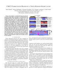
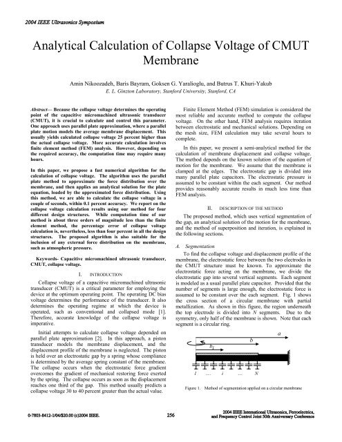
2004 IEEE Ultrasonics Symposium<strong>Analytical</strong> Calculation <strong>of</strong> Collapse Voltage <strong>of</strong> <strong>CMUT</strong>MembraneAmin Nikoozadeh, Baris Bayram, Goksen G. Yaralioglu, and Butrus T. Khuri-YakubE. L. Ginzton Laboratory, Stanford University, Stanford, CAAbstract— Because the <strong>collapse</strong> <strong>voltage</strong> determines the operatingpoint <strong>of</strong> the capacitive micromachined ultrasonic transducer(<strong>CMUT</strong>), it is crucial to calculate and control this parameter.One approach uses parallel plate approximation, where a parallelplate motion models the average <strong>membrane</strong> displacement. Thisusually yields calculated <strong>collapse</strong> <strong>voltage</strong> 25 percent higher thanthe actual <strong>collapse</strong> <strong>voltage</strong>. More accurate <strong>calculation</strong> involvesfinite element method (FEM) analysis. However, depending onthe required accuracy, the computation time may require manyhours.In this paper, we propose a fast numerical algorithm for the<strong>calculation</strong> <strong>of</strong> <strong>collapse</strong> <strong>voltage</strong>. The algorithm uses the parallelplate method to approximate the force distribution over the<strong>membrane</strong>, and then applies an analytical solution for the plateequation, loaded by the approximated force distribution. Usingthis method, we are able to calculate the <strong>collapse</strong> <strong>voltage</strong> in acouple <strong>of</strong> seconds, within 0.1 percent accuracy. We report on the<strong>collapse</strong> <strong>voltage</strong> <strong>calculation</strong> results using our method for fourdifferent design structures. While computation time <strong>of</strong> ourmethod is about three orders <strong>of</strong> magnitude less than the finiteelement method, the percentage error <strong>of</strong> <strong>collapse</strong> <strong>voltage</strong><strong>calculation</strong> is, nevertheless, less than four percent in all the designstructures. The proposed algorithm is also suitable for theinclusion <strong>of</strong> any external force distribution on the <strong>membrane</strong>,such as atmospheric pressure.Keywords- Capacitive micromachined ultrasonic transducer,<strong>CMUT</strong>, <strong>collapse</strong> <strong>voltage</strong>.I. INTRODUCTIONCollapse <strong>voltage</strong> <strong>of</strong> a capacitive micromachined ultrasonictransducer (<strong>CMUT</strong>) is a critical parameter for employing thedevice at the optimum operating point. The operating DC bias<strong>voltage</strong> determines the performance <strong>of</strong> the transducer. It alsodetermines the operating regime at which the device isoperated, such as conventional and <strong>collapse</strong>d mode [1].Therefore, accurate knowledge <strong>of</strong> the <strong>collapse</strong> <strong>voltage</strong> isimperative.Initial attempts to calculate <strong>collapse</strong> <strong>voltage</strong> depended onparallel plate approximation [2]. In this approach, a pistontransducer models the <strong>membrane</strong> displacement, and thedisplacement pr<strong>of</strong>ile <strong>of</strong> the <strong>membrane</strong> is neglected. The pistonis held over an electrostatic gap by a spring whose complianceis determined by the average spring constant <strong>of</strong> the <strong>membrane</strong>.The <strong>collapse</strong> occurs when the electrostatic force gradientovercomes the gradient <strong>of</strong> mechanical restoring force exertedby the spring. The <strong>collapse</strong> occurs as soon as the displacementreaches one third <strong>of</strong> the gap. This method usually predicts a<strong>collapse</strong> <strong>voltage</strong> 30 to 40 percent greater than the actual value.Finite Element Method (FEM) simulation is considered themost reliable and accurate method to compute the <strong>collapse</strong><strong>voltage</strong>. On the other hand, FEM analysis requires iterationbetween electrostatic and mechanical solutions. Depending onthe mesh size, FEM <strong>calculation</strong> may take several hours tocomplete.In this paper, we present a semi-analytical method for the<strong>calculation</strong> <strong>of</strong> <strong>membrane</strong> displacement and <strong>collapse</strong> <strong>voltage</strong>.The method depends on the known solution <strong>of</strong> the equation <strong>of</strong>motion for the <strong>membrane</strong>. We assume that the <strong>membrane</strong> isclamped at the edges. The electrostatic gap is divided intomany parallel plate capacitors. The electrostatic pressure isassumed to be constant within the each segment. Our methodprovides reasonably accurate results in much less time thanFEM analysis.II. DESCRIPTION OF THE METHODThe proposed method, which uses vertical segmentation <strong>of</strong>the gap, an analytical solution <strong>of</strong> the motion for the <strong>membrane</strong>,and the method <strong>of</strong> superposition and iteration, is explained inthe following sections.A. SegmentationTo find the <strong>collapse</strong> <strong>voltage</strong> and displacement pr<strong>of</strong>ile <strong>of</strong> the<strong>membrane</strong>, the electrostatic force between the two electrodes inthe <strong>CMUT</strong> structure must be known. To approximate theelectrostatic force acting on the <strong>membrane</strong>, we divide theelectrostatic gap into several vertical segments. Each segmentis modeled as a usual parallel plate capacitor. Provided that thenumber <strong>of</strong> segments is large enough, the electrostatic force isassumed to be constant over the each segment. Fig. 1 showsthe cross section <strong>of</strong> a circular <strong>membrane</strong> with partialmetallization. As shown in this figure, the region underneaththe top electrode is divided into N segments. Due to thesymmetry, only half <strong>of</strong> the <strong>membrane</strong> is shown. Note that eachsegment is a circular ring.abb i1 … i … NFigure 1. Method <strong>of</strong> segmentation applied on a circular <strong>membrane</strong>0-7803-8412-1/04/$20.00 (c)2004 IEEE.2562004 IEEE International Ultrasonics, Ferroelectrics,and Frequency Control Joint 50th Anniversary Conference
2004 IEEE Ultrasonics Symposiumthe thickness <strong>of</strong> the plate to the outer radius. The smaller thisratio, the more accurate is the solution.D. Superposition and IterationWith the analytical closed-form solution for the equation <strong>of</strong>motion <strong>of</strong> a concentrically loaded circular plate, and thelinearity <strong>of</strong> the equation, we can use the method <strong>of</strong>superposition to find the total solution due to the total forcedistribution. We employ the analytical solution to find aclosed-form solution for each <strong>of</strong> the forces, and thensuperimpose all the solutions.Because the electrostatic force is dependent on the gapheight, we need to iterate the solution. In the first iteration, theelectrostatic force is determined over the non-deflected<strong>membrane</strong>. The atmospheric pressure is added to theelectrostatic force, and with this set <strong>of</strong> forces, we calculate thefirst estimate <strong>of</strong> the displacement pr<strong>of</strong>ile. The next forcedistribution is found by using the new deflection pr<strong>of</strong>ile. Thesesteps are repeated until the solution converges within anacceptable error tolerance. The displacement <strong>of</strong> the center <strong>of</strong>the <strong>membrane</strong> is used as a criterion to determine if the solutionconverges to a final result.We used the geometry depicted in Fig. 3 to compare FEMand our <strong>calculation</strong> method. The <strong>membrane</strong> is underatmospheric pressure. We assumed the bottom electrode coversthe surface <strong>of</strong> the substrate. In this case, the effect <strong>of</strong> parasiticcapacitance is enhanced.Deflection (µm)0-0.02-0.04-0.06-0.08-0.1ModelANSYS-0.120 5 10 15 20Radial distance (µm)Figure 4. Displacement pr<strong>of</strong>ile <strong>of</strong> the <strong>membrane</strong>. The bias <strong>voltage</strong> is 150V,which is less than the <strong>collapse</strong> <strong>voltage</strong>.The <strong>collapse</strong> <strong>voltage</strong> is calculated using a binary searchalgorithm. As mentioned above, the displacement <strong>of</strong> the center<strong>of</strong> the <strong>membrane</strong> is used as a criterion to determine whether thesolution converges or diverges. When the bias <strong>voltage</strong> ishigher than the <strong>collapse</strong> <strong>voltage</strong>, the displacement <strong>of</strong> the center<strong>of</strong> the <strong>membrane</strong> diverges quickly. Fig. 5 compares thedisplacement <strong>of</strong> the center <strong>of</strong> the <strong>membrane</strong> versus number <strong>of</strong>iterations for different DC bias <strong>voltage</strong>s.10 µmSilicon Ox.( ε = 3.78)rVacuum gap20 µmSilicon( ε =11.7)rCenter displacement (µm)105V102V100VFigure 3. <strong>CMUT</strong> geometry. Top and bottom electrodes are shown by blacklines and assumed to be infinitesimally thin in ANSYS <strong>calculation</strong>.Fig. 4 compares the displacement pr<strong>of</strong>ile <strong>of</strong> the middleplane <strong>of</strong> the <strong>membrane</strong> calculated using our method to thepr<strong>of</strong>ile calculated using the FEM analysis. Although thecomputation time is significantly smaller for our algorithm, ourresult is analogous to the FEM simulation, within an acceptableerror for practical purposes.E. Collapse <strong>voltage</strong>When the electrostatic force gradient overcomes therestoring mechanical force, the <strong>membrane</strong> will <strong>collapse</strong> ontothe substrate.Iteration numberFigure 5. Center displacement as function <strong>of</strong> iteration number for variousbias <strong>voltage</strong>s. The <strong>collapse</strong> <strong>voltage</strong> is 104.5V.According to these plots, in all the cases where centerdisplacement converges to a finite value, the second derivative<strong>of</strong> displacement (with respect to the number <strong>of</strong> iterations) isalways negative. For the divergence case, the second derivative<strong>of</strong> the displacement (with respect to the number <strong>of</strong> iterations)becomes zero at a point, and then positive afterwards. Thisobservation can be used as a criterion to distinguish betweenconvergence and divergence, and to decide whether the applied<strong>voltage</strong> is above or below the <strong>collapse</strong> <strong>voltage</strong>. Therefore,using the binary search, we can find the <strong>collapse</strong> <strong>voltage</strong> withthe desired accuracy.0-7803-8412-1/04/$20.00 (c)2004 IEEE.2582004 IEEE International Ultrasonics, Ferroelectrics,and Frequency Control Joint 50th Anniversary Conference
2004 IEEE Ultrasonics SymposiumIII.RESULTSWe compared the results <strong>of</strong> our algorithm with FEMsimulation results, and found that 100 segments over the whole<strong>membrane</strong> are adequate to calculate the <strong>collapse</strong> <strong>voltage</strong>accurately. Our <strong>calculation</strong> took a few seconds; the same<strong>calculation</strong> using FEM analysis would take several hours.Table 1 compares the result <strong>of</strong> our method to FEMsimulations for four different design configurations. All <strong>of</strong>devices are made from Silicon Nitride (Si 3 N 4 ), and have thesame <strong>membrane</strong> thickness <strong>of</strong> 1µm, insulator layer thickness <strong>of</strong>0.1µm, and gap distance <strong>of</strong> 1µm. In order to make a relativelybroad comparison, we changed the radius <strong>of</strong> <strong>membrane</strong>, radius<strong>of</strong> top electrode, and location <strong>of</strong> top electrode. Location <strong>of</strong> topelectrode refers to the relative location <strong>of</strong> top electrode withrespect to the <strong>membrane</strong>: number “1” means that electrode iscompletely on top <strong>of</strong> the <strong>membrane</strong>; number “0” means thatelectrode has been placed underneath the <strong>membrane</strong>.Table 1 shows that our results match the FEM simulation.For all design cases, the results obtained using our method arewithin 5% <strong>of</strong> those obtained with FEM analysis. However, thecomputation time required for our method was approximatelythree orders <strong>of</strong> magnitude less than for FEM analysis.REFERENCES[1] Baris Bayram, Edward Hæggström, Goksen G. Yaralioglu, and B. T.Khuri-Yakub “A New Regime for Operating Capacitive MicromachinedUltrasonic Transducers”, IEEE Trans. Ultrason., Ferroelect., Freq.Contr., vol. 50, pp. 1184-1190, Sep 2003.[2] I. Ladabaum, Xuecheng Jin, H. T. Soh, A. Atalar, and B. T. Khuri-Yakub, “Surface micromachined capacitive ultrasonic transducers,”IEEE Trans. Ultrason., Ferroelect., Freq. Contr., vol. 45, pp. 678-690,May 1998.[3] S. Timoshenko and S. Woinowsky-Krieger, “Theory <strong>of</strong> Plates andShells”, McGraw-Hill book company, Inc., 2 nd ed. 1959.[4] W.P. Mason, “Electromechanical Transducers and Wave Filters”, D.Van Nostrand Company Inc., London, 1948.[5] F.V. Hunt, “Electroacoustics; the analysis <strong>of</strong> transduction, and itshistorical background”, Cambridge: Harvard University Press, 2 nd ed.1982.[6] Butrus T. Khuri-Yakub et al., “Silicon Micromachined UltrasonicTransducers,” Jpn. J. Appl. Phys. 39, 2883-2887 (May 2000).[7] Yaralioglu et al., “Calculation and measurement <strong>of</strong> electromechanicalcoupling coefficient <strong>of</strong> cMUT transducers,” IEEE Trans. Ultrason.,Ferroelect., Freq. Contr., vol. 50, pp. 449-456, April 2003.TABLE I.COMPARISON OF THE METHOD WITH ANSYSDesign parametersFour different design structures# 1 # 2 # 3 # 4Radius <strong>of</strong> <strong>membrane</strong> (µm) 50 50 50 25Radius <strong>of</strong> top electrode (µm) 50 10 50 25Top electrode position 1 1 0 1Our <strong>collapse</strong> <strong>voltage</strong> (volts) 166.7 352.5 131.8 637.7FEM <strong>collapse</strong> <strong>voltage</strong> (volts) 164.8 350.3 126 630.4Percentage error 1.15 0.64 4.6 1.16Our computation time (sec) ~ 2 ~ 2 ~ 2 ~ 4FEM computation time (hours) ~ 4 ~ 4 ~ 4 ~ 4IV. CONCLUSIONWe developed a semi-analytical method to calculate thedisplacement pr<strong>of</strong>ile <strong>of</strong> a circular <strong>membrane</strong>. The same semianalyticalalgorithm was employed to compute the <strong>collapse</strong><strong>voltage</strong> <strong>of</strong> a circular <strong>CMUT</strong> <strong>membrane</strong>.Our tool is extremely useful for the design <strong>of</strong> cMUTdevices. By calculating the displacement pr<strong>of</strong>ile, we can obtainother accurate and useful information, such as devicecapacitance and output pressure. . It is easy to include theatmospheric pressure or, in general, the pressure <strong>of</strong> themedium, as well as residual stresses. As shown in Table 1, theproposed algorithm is quickly calculated, and the accuracy isacceptable for most practical applications.In future work, we will include the fringing capacitance,and also improve the accuracy <strong>of</strong> the algorithm by consideringthe effect <strong>of</strong> shearing stresses and lateral pressures ondeflection <strong>of</strong> the <strong>membrane</strong>. We will also extend the samealgorithm to any <strong>membrane</strong> shape, such as square andhexagonal, where the analytical solution exists.0-7803-8412-1/04/$20.00 (c)2004 IEEE.2592004 IEEE International Ultrasonics, Ferroelectrics,and Frequency Control Joint 50th Anniversary Conference