D:\Carol\My Documents\PDBs\PDRC
D:\Carol\My Documents\PDBs\PDRC
D:\Carol\My Documents\PDBs\PDRC

You also want an ePaper? Increase the reach of your titles
YUMPU automatically turns print PDFs into web optimized ePapers that Google loves.
®<br />
Heating& Air Conditioning<br />
®<br />
Prestige Ultra<br />
RCE High Efficiency<br />
Remote Condensing Units<br />
and Matching Evaporator Coils<br />
HEATING · AIR CONDITIONING<br />
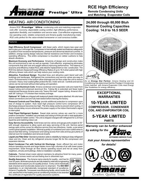
Amana RCE Prestige Ultra condensing units and matching evaporator<br />
coils offer economy, dependable cooling comfort, high efficiency performance,<br />
application flexibility, and installation and service ease. Cost-effective engineering,<br />
low operating costs, reliable components and Amana quality manufacturing make<br />
RCE units perfect for the value-minded homeowner or cost-conscious builder.<br />
24,000 through 60,000 Btuh<br />
Nominal Cooling Capacities<br />
Cooling: 14.0 to 16.5 SEER<br />
Features<br />
High Efficiency Scroll Compressor with fewer parts, which means less wear and<br />
tear to give your unit longer life. Compressor is hermetically sealed and features safeguards<br />
to protect it from excessive temperatures, pressure and abnormal electrical currents. In<br />
addition, energy-saving design reduces internal resistance and friction and increases<br />
operating efficiency. The entire compressor is mounted on rubber cushions to help<br />
absorb vibrations.<br />
Maximum Economy and Performance Simplicity of design and construction make<br />
this unit economical to own as well as operate. Cost-effective engineering eliminates<br />
components that add cost and weight without improving performance. The balance of<br />
economy and efficiency makes RCE units ideal for replacement or new construction. The<br />
RCE line delivers Seasonal Energy Efficiency Ratios of up to 16.5 when paired with high<br />
efficiency blower coils which can help reduce your cooling costs.<br />
Attractive, Functional Design Rounded lines and attractive paint blend well with<br />
buildings and landscape. Refrigerant line connections and service valves are easy to<br />
reach. Embossments in the bottom allow drainage and air flow under the unit to reduce<br />
corrosion. Heavy vinyl-coated grilles protect the fan, motor and coil. Controls and service<br />
valves can be serviced without interrupting unit operation.<br />
Copper and Aluminum Coils Amana condenser and evaporator coils are made from<br />
copper tubing and enhanced aluminum fins. Tubing life is extended and fewer leaks<br />
experienced because Amana uses only “heavy thin-wall” copper tubing. Amana’s thinwall<br />
3/8” tubing is 17% thicker than industry average.<br />
Optional “A” Coils are shipped with leakproof plastic drain pans attached. All coils have<br />
sweat connections and are fully leak tested before leaving the factory.<br />
Pressure Controls and Time Delay provide additional protection to compressor upon<br />
loss of charge to system. Auto reset high pressure control turns compressor off if<br />
discharge pressure becomes too high. The time delay works to prevent short cycling. A<br />
three-minute delay occurs whenever the power supply or the indoor thermostat’s signal<br />
is interrupted.<br />
Field Piped Refrigerant System Sweat style service valves are used for a more<br />
positive connection. Installers can precisely size tubing to fit the job with a neat application<br />
and no waste for better control. The unit is shipped charged with refrigerant for a 25-foot<br />
liquid line and matching indoor coil.<br />
Easy Service Accessibility Solid brass service valves and gauge ports angled at 30°<br />
with enough clearance to allow quick and easy servicing of the unit. Service panel<br />
swings open at the corner for effective service from two directions. Inside, a pre-wired<br />
control panel speeds installation. Minimal quantity of numbered and color-coded wires to<br />
assure fast field wiring. Compressor and tubing access from side and top give plenty of<br />
internal room for installation and removal of parts.<br />
Liquid Line Filter-Drier Standard protection adds to reliability by helping to keep refrigerant<br />
clean and dry. Clean and dry refrigerant ensures longer life for the compressor and<br />
expansion devices.<br />
Quiet Condenser Fan with Vertical Air Discharge Quiet, efficient fan and motor<br />
reduce operating sounds and large blades move high volumes of air with lower power<br />
requirement. Draw through air flow directs operating sound and hot air away from<br />
neighbors, shrubs and buildings. Adds to installation versatility.<br />
Cabinets. Painted sheet metal cabinet maintains its attractive finish for many years.<br />
Cabinet and screws resist rust and fading due to ultraviolet rays.<br />
Quality Assurance The Amana name stands for quality - and has for<br />
over 50 years. All Amana products are fully tested to meet strict engineering<br />
standards and to assure you of a quality product. Every unit is individually<br />
leak checked and functionally tested prior to shipment. The ISO 9001<br />
registration is an internationally recognized standard of excellence.<br />
Amana’s Fayetteville, Tennessee manufacturing facility, which builds this<br />
unit, was the first in the heating and air conditioning industry to be awarded<br />
this certificate of registration for quality assurance systems.<br />
As an Energy Star Partner, Amana Heating and Air<br />
Conditioning has determined that the Prestige II Condensing<br />
Units matched with Amana Evaporator Coils meet Energy<br />
Star Guidelines for energy efficiency.<br />
EXCEPTIONAL<br />
WARRANTIES<br />
10-YEAR LIMITED<br />
COMPRESSOR, CONDENSER<br />
COIL AND EVAPORATOR COIL<br />
Warranty can be further enhanced<br />
by asking for the<br />
Ask your Amana representative<br />
UR<br />
5-YEAR LIMITED<br />
PARTS<br />
L<br />
for details!<br />
C<br />
UR<br />
EXTENDED SERVICE PLAN<br />
L<br />
Heating& Air Conditioning<br />
Comfort. Quality. Trust.<br />
®<br />
TM
®<br />
HEATING • AIR CONDITIONING<br />
General Unit Specifications:<br />
CAPACITIES<br />
Nominal Cooling<br />
Capacity (Btuh)<br />
COMPRESSOR<br />
RCE24A2D RCE30A2D RCE36A2D RCE42A2D RCE48A2D RCE60A2D<br />
24,000 30,000 36,000 42,000 48,000 60,000<br />
R.L. AMPS 10.3 12.2 14.7 16.5 18.3 25.0<br />
L.R. AMPS 56.0 67.0 83.0 95.0 109.0 169.0<br />
CONDENSER FAN MOTOR<br />
Horsepower 1/12 1/4<br />
R.L. AMPS 0.6 2.1<br />
L.R. AMPS 1.2 3.7<br />
SOUND LEVELS (db) 7.2 7.2 7.4 7.6 7.6 7.8<br />
REFRIGERANT LINES<br />
Liquid Line ("O.D.) 3/8<br />
Suction Line ("O.D.) 3/4 7/8 1-1/8<br />
Refrigerant Charge 160.0 oz. 164.0 oz. 230.0 oz. 230.0 oz. 240.0 oz. 250.0 oz.<br />
ELECTRICAL<br />
Power Supply 208/230-60-1<br />
Min.Circuit<br />
Ampacity<br />
Max.Overcurrent<br />
Device<br />
ELECTRICAL CONDUIT SIZE<br />
13.5 16.0 20.5 22.7 25.0 33.4<br />
20 25 35 35 40 55<br />
Power Supply 1/2" or 3/4"<br />
Low Voltage 1/2"<br />
APPROXIMATE SHIPPING WEIGHTS<br />
Weight (lbs.) 208 209 270 272 274 314<br />
Outdoor Unit Dimensions:<br />
MODELS<br />
Dimensions<br />
(square base x height)<br />
RCE24A2D 29" 30"<br />
RCE30A2D 29" 30"<br />
RCE36A2D 35" 34"<br />
RCE42A2D 35" 34"<br />
RCE48A2D 35" 34"<br />
RCE60A2D 35" 38"<br />
2
HEATING • AIR CONDITIONING<br />
®<br />
Specifications:<br />
RCE24A2D with CHA24T*C<br />
Conditions: 80° ID DB, 67° ID WB @ 800 CFM<br />
Outdoor<br />
TOTAL Sensible Latent<br />
Ambient<br />
Btuh Btuh Btuh<br />
°F.<br />
Total Outdoor<br />
Watts<br />
RCE42A2D with CHA42T*C<br />
Conditions: 80° ID DB, 67° ID WB @ 1,400 CFM<br />
Outdoor<br />
TOTAL Sensible<br />
Ambient<br />
Btuh Btuh<br />
°F.<br />
Latent<br />
Btuh<br />
Total<br />
Outdoor<br />
Watts<br />
75° 25,600 171,509 8,450 1,550 75° 42,000 29,400 12,600 2,520<br />
80° 25,300 17,200 8,100 1,600 80° 41,500 29,460 12,040 2,610<br />
85° 25,000 17,250 7,750 1,660 85° 41,000 29,520 11,480 2,700<br />
90° 24,700 17,290 7,410 1,710 90° 40,500 29,560 10,940 2,775<br />
95° 24,400 17,325 7,075 1,760 95° 40,000 29,600 10,400 2,850<br />
100° 23,800 17,250 6,550 1,800 100° 39,000 29,430 9,570 2,915<br />
105° 23,200 17,170 6,030 1,840 105° 38,000 29,260 8,740 2,980<br />
110° 22,350 16,540 5,810 1,875 110° 36,600 29,180 8,420 3,040<br />
115° 21,500 15,910 5,590 1,910 115° 35,200 27,100 8,100 3,100<br />
TVA Conditions @95° OD DB, 75° ID DB, 63° ID WB<br />
TVA Conditions @95° OD DB, 75° ID DB, 63° ID WB<br />
95° 23,900 18,400 5,500 1,600 95° 37,100 29,300 7,800 2,730<br />
RCE30A2D with CHA30T*C<br />
RCE48A2D with CHA54T*C<br />
Conditions: 80° ID DB, 67° ID WB @ 1,000 CFM<br />
Conditions: 80° ID DB, 67° ID WB @ 1,600 CFM<br />
75° 30,200 20,840 9,360 1,850 75° 49,400 34,580 14,820 2,930<br />
80° 29,850 20,890 8,960 1,910 80° 48,800 34,640 14,160 3,035<br />
85° 29,500 20,945 8,555 1,980 85° 48,200 34,700 13,500 3,140<br />
90° 29,150 20,985 8,165 2,040 90° 47,600 34,740 12,860 3,235<br />
95° 28,400 21,025 7,775 2,100 95° 47,000 34,780 12,220 3,330<br />
100° 28,100 20,925 7,175 2,150 100° 45,850 34,590 11,260 3,400<br />
105° 27,400 20,825 6,575 2,200 105° 44,700 34,400 10,300 3,480<br />
110° 26,350 20,020 6,330 2,245 110° 43,050 33,140 9,910 3,620<br />
115° 25,300 19,230 6,070 2,290 115° 41,400 31,880 9,520 3,620<br />
TVA Conditions @95° OD DB, 75° ID DB, 63° ID WB<br />
TVA Conditions @95° OD DB, 75° ID DB, 63° ID WB<br />
95° 27,500 22,550 4,950 2,100 95° 43,600 34,400 9,200 3,180<br />
RCE36A2D with CHA36T*C<br />
Conditions: 80° ID DB, 67° ID WB @ 1,200 CFM<br />
RCE60A2D with CHA60T*C<br />
Conditions: 80° ID DB, 67° ID WB @ 1,800 CFM<br />
75° 37,800 26,080 11,720 2,230 75° 62,000 42,780 19,220 3,830<br />
80° 38,350 26,140 11,210 2,305 80° 61,250 42,865 18,385 3,970<br />
85° 36,900 26,200 1,070 2,380 85° 60,500 42,950 17,550 4,110<br />
90° 36,450 26,240 10,210 2,450 90° 59,750 43,010 16,740 4,230<br />
95° 36,000 26,280 9,720 2,520 95° 59,000 43,070 15,930 4,360<br />
100° 35,100 26,135 8,965 2,575 100° 57,550 42,850 14,700 4,465<br />
105° 34,200 25,990 8,210 2,630 105° 56,100 42,630 13,470 4,570<br />
110° 32,950 25,040 7,910 2,680 110° 54,000 41,035 12,965 4,660<br />
115° 31,700 24,090 7,610 2,730 115° 51,900 39,440 12,460 4,750<br />
TVA Conditions @95° OD DB, 75° ID DB, 63° ID WB<br />
TVA Conditions @95° OD DB, 75° ID DB, 63° ID WB<br />
95° 33,400 26,050 7,350 2,410 95° 54,700 42,660 12,040 4,160<br />
Total gross capacity = Total Btuh + 3.412 x Indoor Watts<br />
Energy Efficiency Ratio (EER) = Total Btuh/Total System Watts<br />
Total System Watts = Total Outdoor Watts + Indoor Watts<br />
3
®<br />
HEATING • AIR CONDITIONING<br />
Unit Model Number Guide:<br />
R C E 36 A 2 D<br />
Product Type<br />
Current<br />
R: Remote Design<br />
Series<br />
System Type<br />
Voltage<br />
C: Cooling 2: 208-230-1-60<br />
Product Family<br />
E: 14 SEER Marketing Designator<br />
A: Standard Line<br />
Coil Model Number Guide:<br />
Nominal Capacity<br />
24: 24,000 Btuh<br />
30: 30,000 Btuh<br />
36: 36,000 Btuh<br />
42: 42,000 Btuh<br />
48: 48,000 Btuh<br />
60: 60,000 Btuh<br />
C C A 24 T C C<br />
Product Type<br />
Design Series<br />
C: Coil A: Series<br />
C: Series<br />
System Type<br />
Cabinet Types<br />
C: Standard Efficiency Cooling S: Uncased<br />
H: High Efficiency Heat Pump C: Cased<br />
D: Wide<br />
K: Extra Wide<br />
Configuration<br />
X: Extra Insulation<br />
A: A-Coil<br />
H: Horizontal Slab Expansion Device<br />
F: Horizontal "A" F: Flowrator (Orifice)<br />
T: TXV (Expansion Valve)<br />
NOTE: This designation deals with<br />
efficiency, not capability. Coils are<br />
designed for both heat pump and<br />
cooling only operation.<br />
NOTE: All measurements are in Standard CFM.<br />
Nominal Size<br />
18: 18,000 Btuh<br />
24: 24,000 Btuh<br />
30: 30,000 Btuh<br />
36: 36,000 Btuh<br />
42: 42,000 Btuh<br />
48: 48,000 Btuh<br />
54: 54,000 Btuh<br />
57: 57,000 Btuh<br />
60: 60,000 Btuh<br />
4
HEATING • AIR CONDITIONING<br />
®<br />
Indoor Coil Specifications & Dimensions** (continued):<br />
CCA18FSC<br />
CCA--F*C & CHA--T*C Uncased A-Coil Specifications<br />
CCA24FSC<br />
CHA18TSC<br />
CCA30FSC<br />
CHA24TSC<br />
CCA36FSC<br />
CHA30TSC<br />
CCA42FSC<br />
CHA36TSC<br />
CCA48FSC<br />
CHA42TSC<br />
CCA54FSC<br />
CHA48TSC<br />
CCA57FSC<br />
CHA54TSC<br />
CCA60FSC<br />
CHA57TSC<br />
CHA60TSC<br />
Evaporator Coil<br />
Face Area (Sq. Ft.) 2.81 2.81 3.75 3.75 4.22 4.69 5.16 5.16 5.63 5.63<br />
Rows 2 3 2 3 3 3 2 3 3 4<br />
FPI 16 14 16 14 13 13 16 14 14 15<br />
Drain Connections<br />
Primary 3/4” FPT 3/4” FPT 3/4” FPT 3/4” FPT 3/4” FPT 3/4” FPT 3/4” FPT 3/4” FPT 3/4” FPT 3/4” FPT<br />
Auxiliary 3/4” FPT 3/4” FPT 3/4” FPT 3/4” FPT 3/4” FPT 3/4” FPT 3/4” FPT 3/4” FPT 3/4” FPT 3/4” FPT<br />
Refrig. Line Connection<br />
Liquid (1) 3/8" 3/8" 3/8" 3/8" 3/8" 3/8" 3/8" 3/8" 3/8" 3/8"<br />
Vapor (1) 5/8" 5/8" 3/4" 3/4" 7/8" 7/8" 7/8" 7/8" 7/8" 7/8"<br />
Shipping Weight (lbs.) 20 21 24 31 35 36 38 45 47 56<br />
(1) Refer to Outdoor Unit Specification Sheet for proper refrigeration line sizes. Use an adapter to fit connection to tubing size, if necessary.<br />
Coil Model and Type<br />
DIMENSIONS (inches)<br />
Orifice Control Coil TXV Coil A B C D<br />
CCA18F*C 12-1/4<br />
CCA24F*C CHA18T*C 12-1/2<br />
CCA30F*C CHA24T*C 16-1/4 15 3 7/16 8 1/8<br />
CCA36F*C CHA30T*C 16-1/2<br />
CCA42F*C CHA36T*C 18-5/8<br />
CCA48F*C CHA42T*C 20-1/4 19 3 7/16 12 1/8<br />
CCA54F*C CHA48T*C 21-5/8<br />
CCA57F*C CHA54T*C 22 23 4 1/4 14 9/16<br />
CCA60F*C CHA57T*C 24<br />
CHA60T*C 24-3/8<br />
NOTE:<br />
The Chart shows the equivalency between orifice and TXV Coils.<br />
Example: Adding TXV Kit to CCA36F*C Coil is equivalent to a CHA30T*C.<br />
9/16<br />
2 5/16<br />
A<br />
1 1/8<br />
20<br />
16 9/16<br />
6<br />
3 3/4<br />
11/16<br />
1 7/8<br />
** All dimensions in inches<br />
3 7/8<br />
C<br />
D<br />
B<br />
5
®<br />
HEATING • AIR CONDITIONING<br />
Indoor Coil Specifications & Dimensions** (continued):<br />
CCA--FCC, CHA--TCC & CHA--TXC Cased Coils<br />
CCA18FCC<br />
CCA24FCC<br />
CHA18TCC<br />
CCA30FCC<br />
CCA30FDC<br />
CHA24TCC<br />
CHA24TXC<br />
CCA36FCC<br />
CCA36FDC<br />
CCA36FKC<br />
CHA30TCC<br />
CHA30TXC<br />
CCA42FCC<br />
CCA42FDC<br />
CHA36TCC<br />
CHA365TXC<br />
CCA48FCC<br />
CCA48FDC<br />
CHA42TXC<br />
CHA42TXC<br />
CCA54FCC<br />
CHA48TCC<br />
CCA57FCC<br />
CHA54TCC<br />
CCA60FCC<br />
CHA57TCC<br />
CHA60TCC<br />
CHA60TXC<br />
Evaporator Coil<br />
Face Area (Sq. Ft.) 2.81 2.81 3.75 3.75 4.22 4.69 5.16 5.16 5.63 5.63<br />
Rows 2 3 2 3 3 3 2 3 3 4<br />
FPI 16 14 16 14 13 13 16 14 14 15<br />
Drain Connections<br />
Primary 3/4” FPT 3/4” FPT 3/4” FPT 3/4” FPT 3/4” FPT 3/4” FPT 3/4” FPT 3/4” FPT 3/4” FPT 3/4” FPT<br />
Auxiliary 3/4” FPT 3/4” FPT 3/4” FPT 3/4” FPT 3/4” FPT 3/4” FPT 3/4” FPT 3/4” FPT 3/4” FPT 3/4” FPT<br />
Refrig. Line Connection<br />
Liquid (1) 3/8" 3/8" 3/8" 3/8" 3/8" 3/8" 3/8" 3/8" 3/8" 3/8"<br />
Vapor (1) 5/8" 5/8" 3/4" 3/4" 7/8" 7/8" 7/8" 7/8" 7/8" 7/8"<br />
Shipping Weight (lbs.) 34 39<br />
43<br />
46 (FDC)<br />
50<br />
53 (FDC)<br />
58 (FKC)<br />
54<br />
57 (FDC)<br />
58<br />
62 (FDC)<br />
(1) Refer to Outdoor Unit Specification Sheet for proper refrigeration line sizes. Use an adapter to fit connection to tubing size, if necessary.<br />
64 71 73 89<br />
Cabinet<br />
Width<br />
(W)<br />
Small<br />
(16 -1/2)<br />
Medium<br />
(20-1/2)<br />
Large<br />
(24-1/2)<br />
CCA--F*C CHA--TCC CHA--TXC<br />
CCA18FCC<br />
Cabinet Height<br />
(H)<br />
CCA24FCC CHA18TCC 14-1/4<br />
CCA30FCC CHA24TCC CHA24TXC<br />
CCA36FCC CHA30TCC CHA30TXC<br />
CCA42FCC CHA36TCC CHA36TXC 22-1/4<br />
CCA30FDC<br />
CCA36FDC<br />
CCA42FDC<br />
CCA48FCC CHA42TCC CHA42TXC<br />
CCA36FKC<br />
CCA48FDC<br />
CCA54FCC<br />
CCA57FCC<br />
CCA60FCC<br />
Horizontal Standard Efficiency Orifice Control Coils<br />
Cased A-Coil Models<br />
CHA48TCC<br />
CHA54TCC<br />
CHA57TCC<br />
CHA60TCC<br />
CHA60TXC<br />
18-1/4<br />
22-1/4<br />
26-1/4<br />
DIMENSION (inches)<br />
Left Air Opening<br />
(A X B)<br />
15 X 18-3/4<br />
19 X 18-3/4<br />
23 X 18-3/4<br />
All air opening flanges are 3/4" except for the two adjacent to the access panel. The flange to the right is 3/16" and the one to the left is 1-5/16".<br />
Right Air Opening<br />
(A X C)<br />
15 X 30-3/16<br />
19 X 20-3/16<br />
23 X 20-3/16<br />
BBA/BBC Matching<br />
Blower Coils<br />
Matches With:<br />
BBA24A2A<br />
BBA36A2A<br />
BBC24A2A<br />
BBA48A2A<br />
BBA60A2A<br />
BBC60A2A<br />
21 1/8<br />
B (Top) or<br />
C (Bottom)<br />
A<br />
H<br />
2<br />
H<br />
7<br />
4 3/4<br />
W<br />
** All dimensions in inches<br />
1 5/8<br />
2 3/4<br />
2<br />
W<br />
1<br />
6
HEATING • AIR CONDITIONING<br />
®<br />
Indoor Coil Specifications & Dimensions** (continued):<br />
Drain Connections<br />
Cased Horizontal Slab Coil Specifications<br />
CCH24FCD<br />
CHH24TCD<br />
CCH30FCD<br />
CHH30TCD<br />
CCH36FCD<br />
CHH36TCD<br />
CCH48FCD<br />
CHH48TCD<br />
CCH60FCD<br />
CHH60TCD<br />
Primary 3/4” FPT 3/4” FPT 3/4” FPT 3/4” FPT 3/4” FPT<br />
Auxiliary 3/4” FPT 3/4” FPT 3/4” FPT 3/4” FPT 3/4” FPT<br />
Refrig. Line Connection<br />
Liquid (1) 3/8" 3/8" 3/8" 3/8" 3/8"<br />
Vapor (1) 5/8" 3/4" 3/4" 7/8" 7/8"<br />
Shipping Weight (lbs.) 38 44 44 60 65<br />
(1) Refer to Outdoor Unit Specification Sheet for proper refrigeration line sizes. Installer may need to supply adapter.<br />
DIMENSION (inches)<br />
Coil Model and Type<br />
Orifice Control Coil TXV Coil A B C D<br />
CCH24FCD<br />
CCH30FCD<br />
CCH36FCD<br />
CHH24TCD<br />
CHH30TCD<br />
CHH36TCD<br />
30-1/2 25 19 21-1/2<br />
CCH48FCD<br />
CCH60FCD<br />
CHH48TCD<br />
CHH60TCD<br />
34-1/2 29 23 25-1/2<br />
NOTE: For standard efficiencies, CCH Coils are the preferred match with RCC Condensing Units. If<br />
higher efficiencies are needed, use CHH Coils.<br />
** All dimensions in inches<br />
7
®<br />
HEATING • AIR CONDITIONING<br />
Indoor Coil Specifications & Dimensions** (continued):<br />
Drain Connections<br />
CCF24FCC<br />
CHF18TCC<br />
CCF24FDC<br />
CCF30FCC<br />
CHF24TCC<br />
CCF36FCC<br />
CHF30TCC<br />
CCF36FDC<br />
CCF42FCC<br />
CHF36TCC<br />
CCF48FCC<br />
CHF42TCC<br />
CCF48FDC<br />
CCF60FCC<br />
CHF48TCC<br />
CCF61FCC<br />
CHF60TCC<br />
Primary 3/4" FPT 3/4" FPT 3/4" FPT 3/4" FPT 3/4" FPT 3/4" FPT 3/4" FPT<br />
Auxilliary 3/4" FPT 3/4" FPT 3/4" FPT 3/4" FPT 3/4" FPT 3/4" FPT 3/4" FPT<br />
Refrig. Line connection<br />
Liquid 3/8" 3/8" 3/8" 3/8" 3/8" 3/8" 3/8"<br />
Vapor* 5/8" 3/4" 3/4" 7/8" 7/8" 7/8" 7/8"<br />
Shipping Weight (lbs.)<br />
CCF--FCC, CHF--TCC & CCF--FDC Cased Horizontal Coils<br />
41 (FCC/TCC)<br />
44 (FDC)<br />
44 (TCC)<br />
48 (FCC)<br />
48 (FCC/TCC)<br />
51 (FDC)<br />
56<br />
56 (FCC/TCC)<br />
59 (FDC)<br />
* Refer to Outdoor Unit Specification Sheet for proper refrigeration line sizes. Installer may need to supply adapter.<br />
72 82<br />
Horizontal Standard Efficiency Orifice Control Coils & Horizontal High Efficiency TXV Coils<br />
Cabinet<br />
Width<br />
(W)<br />
Small<br />
(22-1/4)<br />
Medium<br />
(22-1/4)<br />
Large<br />
(26-1/4)<br />
Horizontal<br />
Standard<br />
Efficiency Orifice<br />
Control Coil<br />
Models<br />
CCF24FCC<br />
CCF30FCC<br />
CCF36FCC<br />
CCF24FDC<br />
CCF36FDC<br />
CCF42FCC<br />
CCF48FCC<br />
CCF48FDC<br />
CCF60FCC<br />
CCF61FCC<br />
Horizontal High<br />
Efficiency TXV<br />
Coil Models<br />
CHF18TCC<br />
CHF24TCC<br />
CHF30TCC<br />
CHF36TCC<br />
CHF42TCC<br />
Cabinet Height<br />
(H)<br />
DIMENSION (inches)<br />
Left Air Opening<br />
(A X B)<br />
Right Air Opening<br />
(A X C)<br />
16-1/2 15 X 18-3/4 15 X 20-3/16<br />
BBA/BBC<br />
Matching<br />
Blower Coils<br />
Matches With:<br />
BBA24A2A<br />
BBA36A2A<br />
BBC24A2A<br />
20-1/2 19 X 18-3/4 19 X 20-3/16 BBA48A2A<br />
CHF48TCC<br />
CHF60TCC 24-1/2 23 X 18-3/4 23 X 20-3/16<br />
BBA60A2A<br />
BBC60A2A<br />
All air opening flanges are 3/4" except for the two adjacent to the access panel. The flange to the right is 3/16" and the one to the left is 1-5/16".<br />
W<br />
1"<br />
A<br />
H<br />
4"<br />
** All dimensions in inches<br />
4"<br />
5"<br />
2" 1-1/2"<br />
8
HEATING • AIR CONDITIONING<br />
®<br />
Specifications (BBA/BBC Blower Coil):<br />
BBA/BBC Blower Specifications (18,000 - 60,000)<br />
Dimensions (BBA/BBC Blower Coil):<br />
BBA24A2A BBA36A2A BBA48A2A BBA60A2A BBC36A2A BBC48A2A BBC60A2A<br />
Cooling Capacity Nominal Btuh 18,000 - 30,000 30,000 - 42,000 36,000 - 60,000 48,000 - 60,000 18,000 - 42,000 30,000 - 48,000 36,000 - 60,000<br />
Blower Motor<br />
Horsepower 1/4 1/3 1/3 1/2 1/2 3/4 3/4<br />
Blower Wheel. Width x Dia. 9 x 7 10 x 7 10 x 10 11 x 10 10 x 7 10 x 10 11 x 10<br />
Rated CFM Cooling 790 1,150 1,380 1,770 1,400 1,550 1,780<br />
Ext. Static Pressure" W.C., Max 1 0.50 0.50 0.5 0.50 0.80 0.80 0.80<br />
Wire Size Determination<br />
NOTE: It is important to electrically connect the unit and properly size fuses/circuit breakers and wires in accordance with all national<br />
and/or local electrical codes.<br />
Use copper wires only.<br />
Power Characteristics 208/230 - 1 -60<br />
Power Supply (w/o Heater Kits)<br />
Min. Circuit Ampacity 2 1.9 3.0 3.8 4.9 5.4 8.8 8.8<br />
Max. Overcurrent Protection 2 15 15 15 15 15 15 15<br />
Approx. Shipping Weight (lbs.) 63 68 78 90 72 82 94<br />
1 With Electric Heater Kit installed<br />
2 Minimum Circuit Ampacity (MCA) and Maximum Overcurrent Protection (MOP) for blower without supplemental heat installed. Refer to<br />
nameplate for MCA and MOP with approved accessory heaters installed.<br />
11 3/8<br />
3 Knockouts<br />
1 - 3/32<br />
1 - 23/64<br />
1 - 23/32<br />
4<br />
2<br />
"H"<br />
"A"<br />
2 1/16<br />
2<br />
7/8 Knockout<br />
Dimensions (inches)<br />
Model A B H W<br />
BBA24A2A 15 15 22-1/4 16-1/2<br />
BBA36A2A 15 15 22-1/4 16-1/2<br />
BBA48A2A 19 19 22-1/4 20-1/2<br />
BBA60A2A 23 23 26-1/4 24-1/2<br />
BBC36A2A 15 15 22-1/4 16-1/2<br />
BBC48A2A 19 19 22-1/4 20-1/2<br />
BBC60A2A 23 23 26-1/4 24-1/2<br />
19 5/8<br />
"B"<br />
21 1/8<br />
"W"<br />
Nomenclature<br />
(BBA/BBC Blower Coil):<br />
B B A 24 A 2 A<br />
Product Type<br />
Design Series<br />
B: Blower Coil A: First Series<br />
System Type<br />
Voltage<br />
B: Multi-positional 2: 230V-1-60<br />
Efficiency<br />
Factory Heat Installed<br />
A: Standard A = 0 kW<br />
C: Variable Speed<br />
Nominal Capacity<br />
24: 24,000 Btuh<br />
36: 36,000 Btuh<br />
48: 48,000 Btuh<br />
60: 60,000 Btuh<br />
9
®<br />
HEATING • AIR CONDITIONING<br />
Specifications: (BMA Airhandler)<br />
BMA24F00A BMA24F05A BMA30F00A BMA30F10A BMA36F00A BMA36F10A BMA42F00A BMA42F10A<br />
NOM. COOLING CAPACITY (TONS) 1.5 & 2 1.5 & 2 2.5 2.5 3 3 3.5 3.5<br />
SUCTION LINE 5/8 5/8 3/4 3/4 3/4 3/4 3/4 3/4<br />
LIQUID LINE 3/8 3/8 3/8 3/8 3/8 3/8 3/8 3/8<br />
DRAIN CONNECTION 3/4 3/4 3/4 3/4 3/4 3/4 3/4 3/4<br />
REFRIGERANT R22 R22 R22 R22 R22 R22 R22 R22<br />
FACTORY INSTALLED ORIFICE 0.062 0.062 0.064 0.064 0.068 0.068 0.073 0.073<br />
FACTORY INSTALLED HEATER none 5 kW none 7 kW none 10 kW none 10 kW<br />
UNIT SIZE (WxDxH) 16.5x21.7x42 16.5x21.7x42 16.5x21.7x42 16.5x21.7x42 19.5x21.7x44 19.5x21.7x44 19.5x21.7x44 19.5x21.7x44<br />
SUPPLY DUCT OPENING 14.5 x 10 14.5 x 10 14.5 x 10 14.5 x 10 17.5 x 10 17.5 x 10 17.5 x 10 17.5 x 10<br />
RETURN DUCT OPENING 20 x 12.5 20 x 12.5 20 x 12.5 20 x 12.5 20 x 15.5 20 x 15.5 20 x 15.5 20 x 15.5<br />
AIR FILTER 15 x 20 x 1 15 x 20 x 1 15 x 20 x 1 15 x 20 x 1 18 x 20 x 1 18 x 20 x 1 18 x 20 x 1 18 x 20 x 1<br />
ELECTRICAL<br />
208-230/60/1 208-230/60/1 208-230/60/1 208-230/60/1 208-230/60/1 208-230/60/1 208-230/60/1 208-230/60/1<br />
24 Vac 24 Vac 24 Vac 24 Vac 24 Vac 24 Vac 24 Vac 24 Vac<br />
BLOWER MOTOR<br />
HORSEPOWER 1/4 1/4 1/3 1/3 1/3 1/3 1/2 1/2<br />
NO. OF BLOWER SPEEDS 3 3 2 2 2 2 2 2<br />
NOM. CFM 600 or 800 600 or 800 1000 1000 1200 1200 1400 1400<br />
UNIT WEIGHT (LBS.) 106 107 120 121 125 126 125 126<br />
Factory installed orifice is for the RHA--B*A heat pump models, refer to the Installation Instructions for other OD unit models.<br />
Line set connection is determined by the OD unit and not by the ID coil connection.<br />
Dimensions:<br />
All dimensions in inches.<br />
16.6 (19.6)<br />
SIDE VIEW (HORIZONTAL)<br />
14.5 (17.5)<br />
10.00<br />
21.7<br />
42.0 (44.0)<br />
TOP VIEW<br />
B M A 24 F 0 0 A<br />
Product Type Florator Design Series<br />
B: Blower Family Metering A: First Series<br />
18.5<br />
3.1<br />
6.0<br />
FRONT VIEW<br />
14.5<br />
1.9<br />
MODEL<br />
System Type<br />
Factory Installed<br />
M: Multi-positional Heat Options<br />
Airhandler 00 = No Installed Heat<br />
05 = 5 kW Factory Installed<br />
Efficiency 10 = 10 kW Factory Installed<br />
A: Standard Motor<br />
DIMENSIONS<br />
W D H<br />
BMA24F**A 16 1/2 21 3/4 42<br />
BMA30F**A 16 1/2 21 3/4 42<br />
BMA36F**A 19 1/2 21 3/4 44<br />
BMA42F**A 19 1/2 21 3/4 44<br />
Nominal Capacity<br />
24: 24,000 Btuh<br />
30: 30,000 Btuh<br />
36: 36,000 Btuh<br />
42: 42,000 Btuh<br />
10
HEATING • AIR CONDITIONING<br />
®<br />
Static Pressure Drop Across Indoor Coil vs. CFM:<br />
CCA18FCC<br />
CCA24FCC<br />
CCA30FCC<br />
CCA30FDC<br />
CCA36FCC<br />
CCA36FDC<br />
CCA36FKC<br />
CCA42FCC<br />
CCA42FDC<br />
CCA48FCC<br />
CCA48FDC CCA54FCC CCA57FCC CCA60FCC<br />
DP<br />
Rated<br />
CFM=600<br />
Rated<br />
CFM=800<br />
Rated<br />
CFM=1,000<br />
Rated<br />
CFM=1,200<br />
Rated<br />
CFM=1,250<br />
Rated<br />
CFM=1,400<br />
Rated<br />
CFM=1,600<br />
Rated<br />
CFM=1,800<br />
Rated<br />
CFM=1,800<br />
(in. w.c.) Dry Wet Dry Wet Dry Wet Dry Wet Dry Wet Dry Wet Dry Wet Dry Wet Dry Wet<br />
0.050 310 330 350 300 --- --- --- --- --- --- --- --- --- --- --- --- --- ---<br />
0.075 455 425 440 380 --- --- --- --- --- --- --- --- --- --- --- --- --- ---<br />
0.100 600 520 530 460 850 600 780 640 750 600 870 690 1170 940 1170 1030 1180 1040<br />
0.125 675 590 605 520 965 680 895 730 890 710 1010 805 1335 1070 1315 1155 1325 1160<br />
0.150 750 660 680 580 1080 760 1010 820 1030 820 1150 920 1500 1200 1460 1280 1470 1280<br />
0.175 825 720 745 630 1180 825 1105 900 1120 895 1270 1020 1635 1310 1585 1390 1590 1405<br />
0.200 900 780 810 680 1280 890 1200 980 1210 970 1390 1120 1770 1420 1710 1500 1710 1530<br />
0.225 --- 835 865 730 1355 955 1275 1040 1330 1065 1515 1215 1890 1515 1790 1600 1850 1630<br />
0.250 --- 890 920 780 1430 1020 1350 1100 1450 1160 1640 1310 2010 1610 1870 1700 1990 1730<br />
0.275 --- --- 970 820 1510 1060 1420 1155 1555 1245 1715 1370 2120 1695 2015 1780 2115 1825<br />
0.300 --- --- 1020 860 1590 1100 1490 1210 1660 1330 1790 1430 2230 1780 2160 1860 2240 1920<br />
CHA24TCC CHA30TCC CHA36TCC CHA42TCC<br />
CHA60TCC<br />
CHA18TCC CHA24TXC CHA30TXC CHA36TXC CHA42TXC CHA48TCC CHA54TCC CHA57TCC CHA60TXC<br />
D P<br />
Rated<br />
CFM=600<br />
Rated<br />
CFM=800<br />
Rated<br />
CFM=1,000<br />
Rated<br />
CFM=1,200<br />
Rated<br />
CFM=1,250<br />
Rated<br />
CFM=1,400<br />
Rated<br />
CFM=1,600<br />
Rated<br />
CFM=1,800<br />
Rated<br />
CFM=1,800<br />
(in. w.c.) Dry Wet Dry Wet Dry Wet Dry Wet Dry Wet Dry Wet Dry Wet Dry Wet Dry Wet<br />
0.050 350 300 --- --- --- --- --- --- --- --- --- --- --- --- --- --- --- ---<br />
0.075 440 380 --- --- --- --- --- --- --- --- --- --- --- --- --- --- --- ---<br />
0.100 530 460 850 600 780 640 750 600 870 690 1,170 940 1,170 1,030 1,180 1,040 1,330 1,190<br />
0.125 605 520 965 680 895 730 890 710 1,010 805 1,335 1,070 1,315 1,155 1,325 1,160 1,485 1,330<br />
0.150 680 580 1,080 760 1,010 820 1,030 820 1,150 920 1,500 1,200 1,460 1,280 1,470 1,280 1,570 1,420<br />
0.175 745 630 1,180 825 1,105 900 1,120 895 1,270 1,020 1,635 1,310 1,585 1,390 1,590 1,405 1,755 1,585<br />
0.200 810 680 1,280 890 1,200 980 1,210 970 1,390 1,120 1,770 1,420 1,710 1,500 1,710 1,530 1,800 1,620<br />
0.225 865 730 1,355 955 1,275 1,040 1,330 1,065 1,515 1,215 1,890 1,515 1,790 1,600 1,850 1,630 1,900 1,715<br />
0.250 920 780 1,430 1,020 1,350 1,100 1,450 1,160 1,640 1,310 2,010 1,610 1,870 1,700 1,990 1,730 2,000 1,810<br />
0.275 970 820 1,510 1,060 1,420 1,155 1,555 1,245 1,715 1,370 2,120 1,695 2,015 1,780 2,115 1,825 2,090 1,905<br />
0.300 1,020 860 1,590 1,100 1,490 1,210 1,660 1,330 1,790 1,430 2,230 1,780 2,160 1,860 2,240 1,920 2,180 2,000<br />
CCH24FCD<br />
CHH24TCD<br />
CCH30FCD<br />
CHH30TCD<br />
CCH36FCD<br />
CHH36TCD<br />
CCH48FCD<br />
CHH48TCD<br />
CCH60FCD<br />
CHH60TCD<br />
D P<br />
(in. w.c.)<br />
Rated<br />
CFM=800<br />
Rated<br />
CFM=1,000<br />
Rated<br />
CFM=1,200<br />
Rated<br />
CFM=1,600<br />
Rated<br />
CFM=1,800<br />
Dry Wet Dry Wet Dry Wet Dry Wet Dry Wet<br />
0.050 760 --- --- --- --- --- --- --- --- ---<br />
0.075 1140 640 --- --- --- --- 810 --- --- ---<br />
0.100 --- 860 820 --- 960 --- 1080 --- 1350 ---<br />
0.125 --- 1070 1020 --- 1090 560 1350 840 1530 ---<br />
0.150 --- --- 1220 760 1220 670 1610 1000 1710 1280<br />
0.175 --- --- --- 890 1340 780 1880 1170 1900 1390<br />
0.200 --- --- --- 1010 1460 890 --- 1340 2100 1490<br />
0.225 --- --- --- 1140 --- 1000 --- 1510 --- 1590<br />
0.250 --- --- --- 1270 --- 1110 --- 1670 --- 1680<br />
0.275 --- --- --- --- --- 1220 --- 1840 --- 1760<br />
0.300 --- --- --- --- --- 1330 --- --- --- 1830<br />
- - Out of Range<br />
DP<br />
(in. w.c.)<br />
CHF18TCC<br />
CCF24FCC<br />
CCF24FDC<br />
Rated<br />
CFM=600<br />
CHF24TCC<br />
CCF30FCC<br />
CCF30FDC<br />
Rated<br />
CFM=1,000<br />
CHF30TCC<br />
CCF36FCC<br />
CCF36FDC<br />
Rated<br />
CFM=1,200<br />
CHF36TCC<br />
CCF42FCC<br />
CCF42FDC<br />
Rated<br />
CFM=1,250<br />
CHF42TCC<br />
CCF48FCC<br />
CCF48FDC<br />
Rated<br />
CFM=1,400<br />
CHF48TCC<br />
CCF60FCC<br />
CCF60FDC<br />
Rated<br />
CFM=1,600<br />
CCF61FCC<br />
CHF60TCC<br />
Dry Wet Dry Wet Dry Wet Dry Wet Dry Wet Dry Wet Dry Wet<br />
0.050 580 440 --- --- --- --- --- --- --- --- --- --- --- ---<br />
0.075 670 520 --- --- --- --- --- --- --- --- --- --- --- ---<br />
0.100 760 600 590 560 670 610 880 750 880 750 1,070 1,010 1,140 1,160<br />
0.125 860 680 680 650 750 690 980 850 980 850 1,200 1,130 1,230 1,240<br />
0.150 950 770 770 730 840 760 1,080 950 1,080 950 1,320 1,250 1,350 1,330<br />
0.175 1,030 830 830 790 910 830 1,180 1,030 1,180 1,030 1,440 1,350 1,440 1,410<br />
0.200 1,120 890 890 850 980 890 1,270 1,110 1,270 1,110 1,550 1,450 1,530 1,490<br />
0.225 1,190 960 960 910 1,040 950 1,350 1,190 1,350 1,190 1,650 1,540 1,620 1,570<br />
0.250 1,260 1,030 1,030 980 1,100 1,000 1,420 1,260 1,420 1,260 1,740 1,640 1,690 1,650<br />
0.275 1,320 1,090 1,090 1,030 1,150 1,050 1,490 1,330 1,490 1,330 1,830 1,730 1,780 1,730<br />
0.300 1,390 1,140 1,140 1,080 1,210 1,100 1,560 1,400 1,560 1,400 1,920 1,820 1,830 1,800<br />
11
®<br />
HEATING • AIR CONDITIONING<br />
Thermostats:<br />
Thermostats M0380101 1213402 1213401 1213408<br />
Man/Auto<br />
Changeover<br />
Man. Man. Man.<br />
Man. or Auto<br />
Changeover<br />
Analog/Digital Analog Digital Digital Digital<br />
Programmable No No Yes Yes<br />
Cool 1 1 1 1<br />
Heat 1 1 1 1<br />
Batt. Powered No Yes Yes No<br />
Batt. Bkup No No No Yes<br />
Color Rect/Vert/Beige Rect/White Rect/White Rect/White<br />
Accessories:<br />
Accessories<br />
Used With<br />
Model Number<br />
Description<br />
RCE24A2D<br />
RCE30A2D<br />
RCE36A2D<br />
RCE42A2D<br />
RCE48A2D<br />
RCE60A2D<br />
EAC5 Electronic Air Cleaner x x x x x x<br />
FSK01A* Freeze Protection Kit x x x x x x<br />
MAC1 Media Air Cleaner x x x x x x<br />
PCK01A Pressure Control Kit x x x x x x<br />
ASC01A Anti Short Cycle Kit x x x x x x<br />
LSK01A Liquid Line Solenoid Kit x x x x x x<br />
x Available for this model<br />
*Note FSK01A for use on indoor coil<br />
Heating& Air Conditioning<br />
Comfort. Quality. Trust.<br />
®<br />
Amana’s continuing commitment to quality products may mean a change in specifications without notice.<br />
Form No. PDRCEA0100 · ©2001 Amana Heating and Air Conditioning · Fayetteville, Tennessee · Printed in U.S.A.<br />
Amana Heating and Air Conditioning, Fayetteville, TN · Registered to ISO 9001 by QMI, Certificate #007062<br />
12