You also want an ePaper? Increase the reach of your titles
YUMPU automatically turns print PDFs into web optimized ePapers that Google loves.
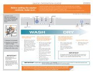
Component Testing Procedures<br />
Connector Locations on the Module Board<br />
The following tests are performed by taking ohm readings on the Module Board connections listed below.<br />
The Module Board can be accessed once the back panel has been removed. See “Component Access Locations.”<br />
1<br />
2<br />
3<br />
1<br />
2<br />
3<br />
4<br />
5<br />
6<br />
7<br />
8<br />
9<br />
4 5 6 7 8 9<br />
COMPONENT CONNECTOR FAULT CODE(S)*<br />
Pressure Switch J3 F04, F05, F07, F08, F10, F15<br />
Heating Eement J2 F14, F15<br />
Door Switch J4 F17<br />
Power in from Surge Protector J1 N/A<br />
Main Motor and Waer Pump J9 F01, F02, F11<br />
Dry NTC Sensor / Condenser Valve ** J10 F13, F14<br />
Fan Motor J16 N/A<br />
Water Valves/Wash NTC J8 F03<br />
Control Panel Board J11 F12<br />
* For more information about how to read Fault Codes and what they mean, see the “Fault Code Chart”<br />
** Condenser Valve ONLY on WDC7100<strong>XC</strong><br />
(Continued on the next page)<br />
Component Testing Procedures 39