
Create successful ePaper yourself
Turn your PDF publications into a flip-book with our unique Google optimized e-Paper software.
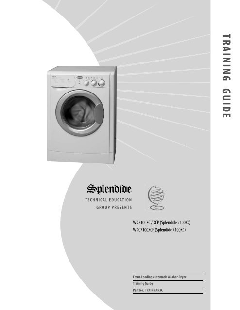
TRAINING GUIDE<br />
<strong>Splendide</strong>®<br />
TECHNICAL EDUCATION<br />
GROUP PRESENTS<br />
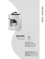
WD2100<strong>XC</strong> / <strong>XC</strong>P (<strong>Splendide</strong> 2100<strong>XC</strong>)<br />
WDC7100<strong>XC</strong>P (<strong>Splendide</strong> 7100<strong>XC</strong>)<br />
Front-Loading Automatic Washer-Dryer<br />
Training Guide<br />
Part No. TRAINMAN<strong>XC</strong>
Contact Info<br />
Product Specifications & Warranty Info<br />
Westland Sales, <strong>Splendide</strong> Tech Dept.<br />
1-800-356-0766 EXT. 5<br />
(503-655-2563)<br />
Technical Assistance & Parts Ordering<br />
Westland Sales, <strong>Splendide</strong> Tech Dept.<br />
1-800-356-0766 EXT. 5<br />
(503-655-2563)<br />
Literature Orders<br />
Westland Sales, <strong>Splendide</strong> Tech Dept.<br />
1-800-356-0766 EXT. 5<br />
(503-655-2563)<br />
Corporate Headquarters<br />
15650 SE 102nd Ave.<br />
(PO BOX 427)<br />
Clackamas, OR 97015<br />
Telephone: 800-356-0766 (503-655-2563)<br />
Service Fax: (503) 722-9202<br />
Service E-mail: service@splendide.com<br />
www.splendide.com/support.htm
Introduction<br />
Westland Sales assumes no responsibility for repairs on <strong>Splendide</strong> products by anyone other<br />
than Authorized <strong>Splendide</strong> Service Technicians. Warranty repairs must be pre-approved by <strong>Splendide</strong>.<br />
Contact Westland Sales, before servicing any <strong>Splendide</strong> appliance.<br />
This Training Guide for the “<strong>Splendide</strong> Front-Loading Automatic Washer-Dryer,” (Part No. TRAINMAN<strong>XC</strong>),<br />
provides the service technician with information on the installation and service of <strong>Splendide</strong> washerdryer<br />
models WD2100<strong>XC</strong> and WDC7100<strong>XC</strong>. It is to be used as a supplemental training aid for service<br />
technicians. For more information on the washer-dryer, refer to the “Use and Care Guide” provided with<br />
the appliance.<br />
Training Guide Goals<br />
The goal of this Training Guide is to provide information that will enable the service technician to properly<br />
diagnose malfunctions and repair the <strong>Splendide</strong> Front-Loading Automatic Washer-Dryer.<br />
The objectives of this Training Guide are for the service technician to:<br />
• understand and follow proper safety precautions,<br />
• effectively troubleshoot and diagnose malfunctions,<br />
• successfully perform necessary repairs, and<br />
• help the technician to quickly return the washer-dryer to its proper operational status<br />
<strong>Splendide</strong> ®<br />
© Copyright 2004, Westland Sales, Clackamas, OR 97015<br />
i
Contents<br />
1. General Information 1<br />
Model / Serial Number Designators 1<br />
Warranty Guide 2<br />
Washer-Dryer Specifications 3<br />
IMPORTANT General Safety Information 4<br />
2. Installation Information 5<br />
Installation Requirements 5<br />
Installation Instructions 9<br />
3. Theory of Operation 13<br />
Introduction to the Models 13<br />
Water System 13<br />
Wash/Dry System 15<br />
Door Lock / Switch Assembly 17<br />
Suspension System 17<br />
Customer Interface / Cycle Selection System 18<br />
Automatic Routines 24<br />
4. Accessing the Components 27<br />
Component Locations 27<br />
Top Panel / Control Panel Knobs 28<br />
Control Panel Board / Control Panel 29<br />
Door / Door Switch / Porthole Diaphragm 30<br />
Detergent Dispenser Assembly / Water Valves 31<br />
Pressure Switch 32<br />
Fan Motor / NTC Sensor / Heater Coil 33<br />
Removing the Heater Coil 34<br />
Lower Panel / Drain Pump / Pump Filter 35<br />
To Clean Out the Large Item Filter 36<br />
Back Panel / Main Motor / Module Board 37<br />
Shock Absorbers 38<br />
(Continued on the next page)<br />
iii
5. Component Testing Procedures 39<br />
Connector Locations on the Module Board 39<br />
Introduction / Instructions 40<br />
1. Door Switch Test 41<br />
2. Power “in” from the Surge Protector Test 42<br />
3. Pressure Switch Test 43<br />
4. Heating Element Test 44<br />
5. Main Motor Test (Includes Running the Main Motor with AC Voltage) 45<br />
6. Fan Motor / Water Pump Test 46<br />
7. Water Valve / Wash NTC Test 47<br />
8. Control Panel Board Test 48<br />
9. Dry NTC Sensor Test 49<br />
6. Diagnosis & Troubleshooting 50<br />
Introduction 50<br />
Explanation of Fault Codes 51<br />
Fault Code / Testing Procedure Chart 52<br />
Problem / Testing Procedure Chart 54<br />
7. Tech Tips 56<br />
<strong>Manual</strong>ly Unlocking the Door 56<br />
Performing a Dryer Airflow & Heat Test 56<br />
Winterization Instructions / Optional RV Winterization 57<br />
Verifying Normal Operation 58<br />
8. Wiring Diagrams 59-61<br />
iv
General Information<br />
Model / Serial No. Designators<br />
Use these numbers to obtain the Warranty status as well as a history of repairs and service calls for the washer-dryer.<br />
To speed the repair process, ALWAYS have the Model and Serial No. ready when you call Westland Sales.<br />
Model Number<br />
PRODUCT GROUP<br />
WD = Washer-Dryer<br />
PRODUCT IDENTIFICATION<br />
C = Condenser Drying System<br />
(Ventless model)<br />
WD C 7100<strong>XC</strong> p<br />
PRODUCT CODE<br />
PRODUCT COLOR Arctic White if not noted<br />
(P = Platinum)<br />
Serial Number<br />
S/N 7 07 14 3277<br />
YEAR OF MANUFACTURE<br />
MONTH OF MANUFACTURE<br />
DAY OF MANUFACTURE<br />
PRODUCT SEQUENCE NUMBER<br />
Model Number<br />
Serial Number<br />
General Information 1
Warranty Guide*<br />
Refer to this page for a brief summary of the Product Warranties available by <strong>Splendide</strong>.<br />
Wty Length <strong>Splendide</strong> Will Pay For <strong>Splendide</strong> WILL NOT Pay For<br />
MFR 1-YEAR<br />
From Date of<br />
Purchase<br />
LIMITED 1-YEAR**<br />
From Date of<br />
Purchase<br />
(Not available for some models)<br />
LIMITED 2-YEAR**<br />
From Date of<br />
Purchase<br />
(Not available for some models)<br />
LIMITED 5-YEAR **<br />
From Date of<br />
Purchase<br />
(Not available for some models)<br />
Replacement parts ONLY.<br />
For 1 year from the date of purchase WHEN product<br />
is registered. Limited replacement parts and repair<br />
labor costs.<br />
For two years from the date of purchase WHEN<br />
extended Protection Plan is purchased. Limited<br />
replacement parts and repair labor costs.<br />
For five years from the date of purchase WHEN<br />
extended Protection Plan is purchased.<br />
A. <strong>Repair</strong>s when the washer-dryer is used in other<br />
than normal, single-family use.<br />
B. Pickup and delivery. The washer-dryer is<br />
designed to be repaired on-site.<br />
C. Removal/replacement of washer-dryer from<br />
built-in or cabinet installations.<br />
D. Damage to the washer-dryer caused by<br />
accident, alterations, misuse, abuse, fire, flood,<br />
acts of God, or use of products not approved by<br />
<strong>Splendide</strong>.<br />
E. <strong>Repair</strong>s to parts or systems resulting from<br />
unauthorized modifications made to the<br />
washer-dryer.<br />
F. Replacement parts or repair labor costs not<br />
pre-approved by <strong>Splendide</strong> and/or provided by<br />
an unauthorized service company.<br />
G. Service calls to correct the installation of the<br />
washer or to instruct you how to use it.<br />
H. Plastic parts and cosmetic pieces.*<br />
*IMPORTANT!<br />
This chart should be used ONLY as a guide and DOES<br />
NOT supersede the Warranty Statement. For complete<br />
information, refer to the Warranty Statement that came with<br />
the appliance.<br />
** Coverage starts 60 days after warranty registration or warranty registration with full payment is<br />
received by Westland Sales.<br />
2<br />
General Information
Washer-Dryer Specifications<br />
The following is a list of product specifications for the <strong>Splendide</strong> Models covered in this Training Guide.<br />
Model Number WD2100<strong>XC</strong> / WD2100<strong>XC</strong>P WDC7100<strong>XC</strong>P<br />
COLOR White Platinum<br />
DRYER TYPE Vented Ventless<br />
ELECTRICAL REQ.<br />
Max. Current 11A 11A<br />
Rated Current 15 A 15 A<br />
Voltage 120V 120V<br />
Frequency 60Hz 60Hz<br />
Heating Power 1300W 1300W<br />
GALLONS WATER PER ‘Regular Cotton<br />
7.5 Gal. 7.5 Gal.<br />
Heavy Duty’ cycle*<br />
MAX. LOAD CAPACITY<br />
Wash 15 lb. 15 lb.<br />
Dry 11 lb. 11 lb.<br />
MAX. SPIN SPEED 1200 RPM 1200 RPM<br />
Height 33 1/4” 33 1/4”<br />
Width 23 1/2” 23 1/2”<br />
Depth 22 3/16” 22 3/16”<br />
WEIGHT 148 lb. 148 lb.<br />
PROGRAMS<br />
Wash 9 Cycles 9 Cycles<br />
Dry 3 Cycles 3 Cycles<br />
WASH TEMP OPTIONS 7 7<br />
SPECIAL WASH OPTIONS 4 buttons 4 buttons<br />
*Avg. wash water use is 7.5-16 gal/wash load. Water usage varies depending on load size and fabric type.<br />
NOTE: WDC7100<strong>XC</strong> has a condenser (ventless) drying system. This condenser drying system uses 2.5<br />
gallons of cold water per hour during the dry cycle.<br />
General Information 3
IMPORTANT General Safety Information<br />
Your safety is important. Read this section before you continue.<br />
Important safety messages can be found in this manual and on<br />
the appliance. Always read and obey all safety messages.<br />
!<br />
This is a safety alert symbol. This symbol<br />
alerts you to potential hazards that can kill or<br />
hurt you and others. All safety messages will<br />
follow the safety alert symbol and the word<br />
“WARNING.”<br />
The safety messages will tell you what the potential hazard is,<br />
tell you how to reduce the chance of injury, and tell you what can<br />
happen if the instructions are not followed.<br />
!<br />
WARNING<br />
ELECTRICAL SHOCK HAZARD<br />
Plug washer-dryer into a<br />
grounded 3 prong outlet.<br />
Do not remove ground prong.<br />
Do not use adapter.<br />
Do not use an extension cord.<br />
Failure to follow these<br />
instructions can result in death,<br />
fire, or electrical shock.<br />
!<br />
!<br />
WARNING<br />
ELECTRICAL SHOCK HAZARD<br />
Disconnect power before servicing.<br />
Replace all panels before operating.<br />
Failure to do so can result in death<br />
or electrical shock.<br />
WARNING<br />
E<strong>XC</strong>ESSIVE WEIGHT HAZARD<br />
Use two or more people to move<br />
and install the washer-dryer.<br />
Failure to do so can result in back<br />
or other injury<br />
Electrostatic Discharge (ESD)<br />
Sensitive Electronics<br />
ESD problems are present everywhere. ESD may damage or<br />
weaken the electronic control assembly. The new control assembly<br />
may appear to work well after repair is finished, but failure may<br />
occur at a later date due to ESD stress.<br />
• Use an antistatic wrist strap. Connect the wrist strap to a green<br />
ground connection point or unpainted metal in the appliance;<br />
or touch your finger repeatedly to a green ground connection<br />
point or unpainted metal in the appliance.<br />
• Avoid touching electronic parts or terminal contacts. Handle<br />
the Module Board by the plastic housing ONLY.<br />
4<br />
General Information
Installation Information<br />
Installation Requirements<br />
Check these location, plumbing and electrical installation requirements for a proper washer-dryer installation.<br />
Electrical<br />
• Machine Voltage/Amperage - 120V, 60 Hz, 1300<br />
W, 10.5 Amp.<br />
• Connection - 3-prong plug with 6’ cord is<br />
provided with the machine.<br />
• Circuit/Protector - 3-wire single phase, 120V, 60<br />
Hz, AC, on a separate 15 Amp circuit.<br />
Location<br />
• This machine may be installed free standing as<br />
well as in a recessed area, closet, or alcove<br />
If you have...<br />
no access to Hot/<br />
Cold water hookups<br />
to install a dryer<br />
vent and ducting in<br />
your RV or boat<br />
concerns about the<br />
appliance shifting in<br />
your RV or boat<br />
water damage<br />
concerns<br />
to make a 90” duct<br />
turn in less than 4.5”<br />
You’ll need...<br />
<strong>Splendide</strong> Faucet Adapter Kit, or<br />
equivalent.<br />
<strong>Splendide</strong> Vent Kit, or equivalent.<br />
<strong>Splendide</strong> SecureFit bracket kit, or<br />
equivalent.<br />
<strong>Splendide</strong> Drain-A-Way Pan, or equivalent.<br />
<strong>Splendide</strong> 90˚ offset elbow, or equivalent.<br />
• Minimum Installation Spacing - 0” on sides<br />
and 1” in front and back. NOTE: Additional<br />
installation spacing needs to be considered for<br />
easy installation, servicing, and compliance with<br />
state and federal codes.<br />
• Floor - Must support at least 280 lbs. and be a<br />
solid, level surface. DO NOT install on carpet.<br />
• RV/Marine Installations - When locating the<br />
appliance in a towable trailer or watercraft,<br />
position the machine over the axles or mid-ship<br />
where movement is at a minimum. Block the<br />
machine to prevent extreme movement.<br />
• Exhaust Requirements (WD2100<strong>XC</strong> Model<br />
ONLY) - Rigid or flexible metallic duct required.<br />
Ducting should be as short and straight as<br />
possible. DO NOT exhaust dryer into a chimney,<br />
furnace, cold air duct, attic crawl space, or<br />
another duct used for venting. If a cabinet door<br />
is installed, a minimum of 8 sq. in. should be<br />
provided for make up air. Louvered doors with<br />
equivalent air openings are acceptable. Allow<br />
clearances behind door(s) to avoid rubbing<br />
between back of cabinet door(s) and front of unit<br />
control panel. Additional clearances for wall, door<br />
and floor moldings may be required.<br />
Drainage<br />
• Standpipe Diameter/Capacity - Needs a 1 ¼”<br />
minimum diameter standpipe with a minimum<br />
carry-away capacity of 7 gallons per minute.<br />
• Top of Standpipe - Must be between 25” and<br />
34” high from the bottom of the machine.<br />
• Outlet End of Drain Hose (provided with the<br />
unit) - Must be at least 20” above the bottom of<br />
the washer-dryer. An air break must be available<br />
at the standpipe to avoid siphoning. No more than<br />
6” of the drain hose should be inserted into the<br />
drain pipe to prevent siphoning.<br />
Installation Information 5
Washer-Dryer Dimensions<br />
<br />
<br />
<br />
<br />
Undercounter Install Requirements<br />
The dimensions shown are for the minimum spacing allowed.<br />
0 in.<br />
(0 cm)<br />
<br />
<br />
33-1/4 in.<br />
(84.5 cm)<br />
0 in.<br />
(0 cm)<br />
23-1/2 in.<br />
(59.7 cm)<br />
0 in.<br />
(0 cm)<br />
<br />
<br />
Recessed Area/Closet Install Requirements<br />
The dimensions shown are for the minimum spacing allowed.<br />
<br />
<br />
<br />
<br />
<br />
<br />
Additional spacing should be considered for:<br />
• Ease of installation and servicing.<br />
• Additional clearances might be required for wall, door and floor<br />
moldings.<br />
• If cabinet door is installed, a minimum of 8 sq. in. should be<br />
provided for make up air. Louvered doors with equivalent air<br />
openings are acceptable.<br />
6<br />
Installation Information
Drain System Requirements<br />
The washer-dryer can be installed using the standpipe drain<br />
system, floor drain system or the sink drain system. To prevent<br />
siphoning, the outlet end of the drain hose MUST always be 20”<br />
(50.8 cm) above the base of the machine. Not more than 6” (15.24<br />
cm) of the drain hose should be inserted into the drain pipe.<br />
Sink Drain W/ "Y" Branch Tailpiece<br />
25" (62 cm) min.<br />
with an air break<br />
Laundry Sink Drain<br />
Floor Standpipe<br />
Wall Standpipe<br />
Cable tie<br />
A<br />
B<br />
This connection MUST be<br />
before drain trap and at<br />
least 20" (50.8 cm) above<br />
the floor where washer will<br />
be installed.<br />
"Y" Tail Piece<br />
Standpipe<br />
20" (51.8 cm) min.<br />
34" (86 cm) max.<br />
Floor Standpipe w/ "Y" Branch Tail Piece Fig. 7<br />
A & B = 25" (62 cm) min. / 34" (86 cm) max.<br />
The standpipe drain requires a minimum diameter standpipe of<br />
1-1/4” (3.2 cm). The minimum carry-away capacity can be no less<br />
than 7 gal (26.5 L) per minute.<br />
The top of the standpipe must be at least 25 in. (62 cm) high and<br />
no higher than 34” (86 cm) from the bottom of the washer.<br />
The floor drain system requires a siphon break that may be<br />
purchased separately.<br />
The sink drain system connected to a garbage disposer requires a<br />
“Y” connector (sold separately.<br />
Optional<br />
• The <strong>Splendide</strong> Faucet<br />
Adapter Kit, Part No.<br />
154187104A<br />
• Supplies water from the<br />
faucet and discharges<br />
water directly into the sink.<br />
• Designed for installations<br />
where washer-dryer hookups<br />
are not available.<br />
Faucet Adapter Kit, Part No.<br />
154187104A<br />
(Continued on the next page)<br />
U-Clamp<br />
6" max.<br />
25" (62 cm) min.<br />
34" (86 cm) max.<br />
Standpipe<br />
20" (50 cm) min.<br />
with an air break<br />
Installation Information 7
Electrical Requirements<br />
GROUNDING INSTRUCTIONS<br />
This appliance must be grounded. In the event of a malfunction,<br />
or breakdown, grounding will reduce the risk of electric<br />
shock by providing a path of least resistance for electric<br />
current. This appliance is equipped with a cord having an<br />
equipment grounding conductor and grounding plug. The<br />
plug must be plugged into an appropriate outlet that is<br />
properly installed and grounded in accordance with all local<br />
codes and ordinances. DO NOT modify the plug provided with<br />
the appliance. If it will not fit the outlet, have the proper outlet<br />
installed by a qualified electrician.<br />
WARNING: Improper connection of the equipmentgrounding<br />
conductor can result in a risk of electric shock.<br />
Check with a qualified electrician or serviceman if you<br />
are in doubt as to whether the appliance is properly<br />
grounded.<br />
!<br />
WARNING<br />
ELECTRICAL SHOCK HAZARD<br />
Plug washer-dryer into a<br />
grounded 3 prong outlet.<br />
Do not remove ground prong.<br />
Do not use adapter.<br />
Do not use an extension cord.<br />
Failure to follow these<br />
instructions can result in death,<br />
fire, or electrical shock.<br />
• A 120-volt, 60-Hz., AC-only, 15 or 20-amp, fused electrical<br />
supply is required. Time-delay fuse or circuit breaker is recommended.<br />
It is recommended that a separate circuit serving only<br />
this appliance be provided.<br />
• This washer-dryer is equipped with a power supply cord having a<br />
3-prong ground plug.<br />
• To minimize possible shock hazard, the cord must be plugged<br />
into a mating, 3-prong, ground-type outlet, grounded in accordance<br />
with local codes and ordinances. If a mating outlet is<br />
not available, it is the personal responsibility and obligation of<br />
the customer to have the properly grounded outlet installed by a<br />
qualified electrician.<br />
• If codes permit and a separate ground wire is used, it is recommended<br />
that a qualified electrician determine that the ground<br />
path is adequate.<br />
• Do not ground to a gas pipe.<br />
• Check with a qualified electrician if you are not sure the washer<br />
is properly grounded.<br />
• DO NOT use an extension cord.<br />
• Do not have a fuse in the neutral or ground circuit.<br />
• DO NOT install or store this appliance where it will be exposed to<br />
weather or in an area where gasoline or other flammables are<br />
stored.<br />
8<br />
Installation Information
Installation Instructions<br />
Follow these instructions in order to prevent installation errors and to assure proper washer-dryer operation.<br />
Unpacking the washer-dryer<br />
• Carefully remove the packing materials with care<br />
not to damage the drain hose and power cord<br />
that are shipped installed on the machine. Check<br />
that the machine is intact. Report any damage<br />
immediately.<br />
• Position the washer-dryer near the desired<br />
installation position.<br />
WARNING: Plastic bags, styrofoam, nails<br />
and other packaging parts are not children’s<br />
toys and can be potentially dangerous.<br />
Destroy the carton and plastic bags after the<br />
washer-dryer has been unpacked.<br />
Removing the transit screws<br />
For transportation, the inside of the machine is supported<br />
by screws, rubber grommets and spacers on the back<br />
panel. Before using the washer-dryer, these items MUST<br />
be removed.<br />
IMPORTANT: Transit screws and spacers must be<br />
removed before operating the machine to allow<br />
proper operation of the machine and to prevent<br />
damage to the appliance.<br />
• After positioning<br />
the washer-dryer<br />
near the installation<br />
location, remove the<br />
four screws (Fig.1),<br />
with the rubber<br />
grommets and plastic<br />
spacers that are<br />
attached to them.<br />
• Use the plastic plugs<br />
(provided in the accessories bag) to fill in the holes.<br />
Connecting the water inlets<br />
If the water pipes you will be connecting to are<br />
new or unused, run the water until clear to remove<br />
any debris that could clog the water valve screens<br />
or valves before connecting the machine. NOTE:<br />
Supply shut-off valves should be easily accessible.<br />
IMPORTANT: Water pressure MUST<br />
range within the values indicated on the<br />
“Technical Data” chart<br />
• Included in the accessories supplied with<br />
your machine are 2 inlet hoses with 4 rubber<br />
washers pre installed. Check that the rubber<br />
washers are installed in the ends of the inlet<br />
hoses to make a water tight seal at each<br />
connection point.<br />
• Connect the straight ends of the water inlet<br />
hoses to the<br />
supply taps<br />
that have ¾”<br />
BSP thread<br />
(standard hose<br />
bib).<br />
• Connect the<br />
90º angled<br />
ends (20 mm<br />
thread) of<br />
these hoses to<br />
the inlet valves<br />
on the back of the machine (Fig. 2). NOTE:<br />
Water Inlet valves are color coded: Red (Hot) &<br />
White (Cold).<br />
IMPORTANT: Do not use excessive force.<br />
Damage to the couplings can result. The<br />
couplings should be tightened by hand; a<br />
tool should only be used if a leak occurs.<br />
IMPORTANT: Retain the transit screws, spacers and<br />
rubber tubes. These items should be reinstalled to<br />
prevent damage if or when you transport the machine<br />
in the future.<br />
Installation Information 9
Connecting the drain hose<br />
It is possible for the water to be discharged into a sink,<br />
standpipe or drainpipe, but an air break must be available<br />
at a minimum 20” height to prevent the machine from<br />
siphoning (Fig. 6).<br />
the floor to a separate trap. The trap must be vented<br />
to prevent siphoning. To provide proper venting, install<br />
an Air Gap Kit (available at most hardware stores).<br />
4) To the faucet using a Faucet Adapter Kit (available<br />
separately).<br />
IMPORTANT: Make sure that the drain hose<br />
is not kinked and that water flow is not<br />
restricted.<br />
Standpipe Drain System - Installations require a minimum<br />
1 ¼” (3.2 cm) diameter standpipe with a minimum<br />
carry away capacity of 7 gallons (26 liters) per minute.<br />
Wall or Floor Standpipe Drain System - The top of the<br />
standpipe must be between 25” (62 cm) - 34” (86 cm)<br />
from the bottom of the washer (Fig. 4).<br />
• Use a U-Clamp (provided in your accessories<br />
packet) or suitable item to secure the outlet end<br />
of the drain hose (pre-installed on the back of<br />
your machine).<br />
• Insert the outlet end of the drain hose into the<br />
standpipe, wall or floor drain (Fig. 6). NOTE: The<br />
outlet end of the drain hose MUST be at least<br />
20” (50 cm) above the base of the machine.<br />
No more than 6” of the drain hose should be<br />
inserted into the drain pipe to prevent siphoning.<br />
• Use a strap, cable tie, or similar item to hold the<br />
hose or the U-Clamp in place.<br />
Sink Drainpipe System - Entry into the sink drain<br />
system must be above the trap (Fig. 5). When routing<br />
the drain hose through cabinets or walls, use a protective<br />
material such as electrical or duct tape to cover sharp<br />
edges that could damage the drain hose. Use a suitable<br />
clamp to secure the drain hose to the “Y” branch or the<br />
disposer (Fig. 7). With a sink drainpipe system, you may<br />
connect directly: 1) to a disposer by following the manufacturers<br />
attachment method. 2) directly to a “Y” branch<br />
tail piece (available at most hardware stores). 3) Through<br />
10<br />
Installation Information
Installing the exhaust ducting<br />
(WD2100<strong>XC</strong> Model ONLY)<br />
•<br />
•<br />
•<br />
•<br />
•<br />
IMPORTANT: This<br />
appliance should NOT<br />
be exhausted into a<br />
chimney, wall, ceiling,<br />
or any concealed space<br />
of a building. Only<br />
rigid or flexible metallic<br />
ducting should be<br />
used.<br />
Rigid or flex metal/metallic ducting should be used.<br />
Exhaust ducts should be as short and straight as<br />
possible. NOTE: Long exhaust ducting can extend<br />
drying time, collect lint and may affect drying<br />
performance.<br />
The exhaust duct must end with an approved<br />
exhaust vent hood with swing out damper(s) or<br />
tailpiece with louvers.<br />
Check that all ducting is clean and lint free. Use<br />
duct tape or screw clamps to secure all joints.<br />
Use duct tape or screw clamps to secure the duct<br />
to the round flange vent located on the back of the<br />
machine (Fig. 8).<br />
Leveling the washer-dryer<br />
(All Models)<br />
• To access the<br />
front leveling legs,<br />
tilt the machine<br />
backwards,<br />
leaning it against<br />
a wall or other<br />
stable structure.<br />
• Adjust the legs<br />
up or down (Fig.<br />
9) to ensure<br />
the washer is resting solid and does not<br />
rock side-to-side or front-to-back when the<br />
machine is upright.<br />
• Check that the angle of inclination,<br />
measured according to the work top, does<br />
not exceed 2°.<br />
IMPORTANT: The machine must rest solid on<br />
a sturdy floor for optimum performance and<br />
minimum vibration.<br />
WD2100<strong>XC</strong> WARNING! -To reduce the risk of fire,<br />
this appliance must be exhausted to the outdoors.<br />
Rigid or flexible metallic duct required. Ducting must<br />
be as short and straight as possible.<br />
Do not exhaust dryer into a chimney, furnace, cold<br />
air duct, attic crawl space, or another duct used for<br />
venting.<br />
If a cabinet door is installed, a min. opening of 8 sq.<br />
in. should be provided for make up air. Louvered<br />
doors with equivalent air openings are acceptable.<br />
Allow clearances behind door(s) to avoid rubbing<br />
between back of cabinet door(s) and front control<br />
panel. Additional clearances for all, door and floor<br />
molding may be required.<br />
Installation Information 11
Completing the installation<br />
•<br />
•<br />
•<br />
•<br />
•<br />
•<br />
•<br />
•<br />
Check the electrical requirements. Be sure<br />
that you have the correct electrical supply and<br />
the recommended grounding method.<br />
Check that the shipping brackets have been<br />
removed.<br />
Check that the water faucets are ON.<br />
Check for leaks around faucets and inlet<br />
hoses.<br />
Plug washer into a grounded 3-prong outlet.<br />
Slide the washer-dryer to it’s final location and<br />
confirm that it’s level.<br />
When installing this appliance in an RV or<br />
marine vessel, you should block in the unit to<br />
prevent it from shifting or tipping. A SecureFit<br />
Bracket Kit is available from <strong>Splendide</strong> to keep<br />
the unit from shifting front-to-back or side-toside.<br />
Test and clean the washer. Run a test load<br />
with no laundry.<br />
Testing and cleaning the washer,<br />
• Press the ON-OFF button to turn the washer<br />
ON<br />
• Pour 1 to 2 TBSP of powder detergent into<br />
the detergent dispenser compartment ‘2’<br />
• Select wash program ‘2’.<br />
• Make sure the DRY TIME knob is in the ‘OFF’<br />
position.<br />
• Then press START. Allow the washer to complete<br />
the wash cycle.<br />
12
Theory of Operation<br />
Introduction<br />
The <strong>Splendide</strong> Front-Loading Washer-Dryer models present many new features and characteristics that<br />
are different from previous models. In addition to the introduction of electronic controls, the washerdryer<br />
contains a number of unique operating features designed to offer extremely high water and<br />
energy conservation while increasing fabric cleaning results.<br />
Water System<br />
The water system consists of the hot and cold water inlet valves and the dispenser distribution system<br />
along with a traditional pressure switch.<br />
Water Inlet Valves<br />
The hot and cold water inlet valves are located at the back, top-left of the washer. These valves receive a<br />
control signal from the Module Board to manage the temperature of incoming water. The temperatures<br />
are determined by the specific wash temperature selected. (See chart on next page)<br />
Dispenser Distribution System<br />
All wash and rinse water is introduced into the drum through a Dispenser Distribution System that diverts<br />
the incoming water to one or more of the follow water inlet modes: Detergent Dispensing, Bleach<br />
Dispensing, Fabric Softener Dispensing. The dispenser drawer has three separate compartments (plus<br />
one removable bin) for adding laundry products to the wash load. These compartments are:<br />
1. Prewash Detergent (w/removable<br />
Bleach Bin)<br />
2. Main Wash Detergent<br />
3. Fabric Softener Compartment<br />
All of the water flows through<br />
the dispenser assembly. Laundry<br />
products are diluted and<br />
dispensed automatically at the<br />
proper time during the wash cycle.<br />
Refer to “Use and Care Guide”<br />
that came with the appliance for<br />
proper use of laundry aids.<br />
Theory of Operation 13
Pressure Switch<br />
The pressure switch is located in the top, right-front corner of the washer. This switch senses the water<br />
level in the drum. The control signal from the pressure switch is sent to the Module Board and is used to<br />
determine the amount of water introduced into the drum during the wash cycle.<br />
Pressure Switch<br />
WASH TEMP Knob Position Wash Temp.*<br />
HOT (Red) 1:30 140°F / 60° C<br />
3 o’clock 131°F / 55° C<br />
WARM (Grey) 4:30 122°F / 50° C<br />
6 o’clock 104°F / 40° C<br />
7:30 95°F / 35° C<br />
COLD (Blue) 9 o’clock 86°F / 30° C<br />
10:30 FROM COLD VALVE ONLY<br />
12 o’clock FROM COLD VALVE ONLY<br />
*NOTE: Actual wash water temperatures may vary depending on the<br />
temperature set at the water heater. Rinse temperatures are ALWAYS COLD.<br />
14<br />
Theory of Operation
Wash/Dry System<br />
The Wash/Dry System consists of the Module Board, the Main Motor, the Pump Motor and the<br />
Dryer Heating Element.<br />
Module Board<br />
The Module Board is located at the bottom,<br />
right-rear corner of the washer-dryer. If<br />
diagnostic tests indicate that the module<br />
board is defective, the entire module board<br />
must be replaced.<br />
The module board receives input from the<br />
Control Panel/LED assembly and directly<br />
controls the dispenser, drain pump, water inlet valves, door locking and unlocking, fan motor<br />
and heating element relay. The module board monitors the pressure switch, and door lock<br />
switches.<br />
Main Motor<br />
The main motor is located at the bottom,<br />
rear of the washer and is an infinite speed,<br />
3 phase brushless motor that operates at<br />
various speeds and directions based on<br />
input voltages from the module board.<br />
(Continued on the next page)<br />
Theory of Operation 15
Pump Motor<br />
A separate pump/pump motor is used to drain the drum (Fig. 3-1). The pump motor is 120 VAC and is<br />
attached directly to the pump. The pump has a filter located at the bottom-front that allows for the<br />
removal of large objects like keys and coins that may have passed from the basket. (Fig. 3-2)<br />
Drain Pump<br />
Large Object Filter<br />
Dryer Heating Element<br />
The Dryer Heating Element is located in the heater<br />
duct assembly on the top-right of the drum. The<br />
Module Board provides power to the element in<br />
the dry cycle. During the dry cycle:<br />
• Vented model (WD2100<strong>XC</strong>) take air from the<br />
surrounding room, heat it, tumble it through the<br />
clothes, and then exhaust it to the outside through<br />
a vent.<br />
• Ventless model (WDC7100<strong>XC</strong>) require 2.5<br />
gallons of cold water per hour during the dry cycle.<br />
(See below.)<br />
Dryer Heating Element<br />
How Does Ventless Drying Work<br />
1. As damp laundry tumbles, the inner drum is heated. Heat draws the moisture out of the laundry in the<br />
form of STEAM.<br />
2. Cold water cools the OUTER TUB. The cold surface attracts the warm, saturated air. STEAM passes through<br />
the holes in the INNER DRUM to reach the OUTER TUB.<br />
3. When the STEAM hits the cooled surface of the OUTER TUB, it’s condensed back into water. The water is<br />
then pumped out the drain. Process repeats until clothes are dry.<br />
NOTE: Do not attempt to dry less than 2.2 lbs of laundry during the Cotton Heavy Duty Dry cycle.<br />
16<br />
Theory of Operation
Door Lock/Switch Assembly<br />
The Door Lock/Switch Assembly is located on<br />
the right side of the door opening. The assembly<br />
contains a solinoid operated latching mechanism<br />
that will electrically lock the door during a wash or<br />
dry cycle.<br />
Door Lock/Switch Assembly<br />
Suspension System<br />
The drum assembly is held in position with two shock absorbers attached to the bottom sides of the<br />
tub assembly. In addition, the drum is suspended from the top frame of the washer with three springs<br />
attached to the sides of the case.<br />
Stability for this suspension system is provided by two concrete counter weights. One is located at the<br />
top and one at the bottom-front of the outer drum.<br />
Springs<br />
Top Counter Weight<br />
Bottom/Front<br />
Counter Weight<br />
Shock Absorbers<br />
Theory of Operation 17
Customer Interface / Cycle Selection System<br />
The Customer Interface / Cycle Selection System consists of the Control Panel/LED Assembly along with<br />
the program timer, option buttons, and Wash Temperature and Dry Time Selectors.<br />
Control Panel/LED Assembly<br />
The Control Panel/LED Assembly (Fig. 3-3) is removed as a single assembly and is connected to the<br />
Module Board by 5 connection points to the wiring harness.<br />
The assembly contains all the buttons, LED’s and switches for the user to operate the washer-dryer.<br />
This interfaces what the consumer commands to the Module Board.<br />
18<br />
Theory of Operation
Description of Control Panel Buttons, Knobs & LED’s<br />
ON/OFF Button- Use the ON/OFF Button to turn machine power ON or OFF<br />
START Button- Use this button to START a cycle (press once) or RESET the controls (press and hold for 5<br />
seconds). For more information, see “Resetting the Controls” on page 20.<br />
Option Buttons<br />
START/RESET<br />
Button<br />
Door Lock<br />
LED<br />
ON/OFF<br />
Button<br />
Cycle<br />
Status<br />
LED’s<br />
Dry Time<br />
Selector<br />
Wash Temp.<br />
Selector<br />
Cycle Selector<br />
Option Buttons - Use these buttons to modify the wash cycle (see “Description of Option Buttons”)<br />
Door Lock Light - This light indicates when the door is locked (LIT SOLID) and when it can be safely<br />
opened (BLINKING).<br />
Water Temperature Selector - Choose a water temperature by turning the knob to the desired selection.<br />
Refer to the garment label and choose the warmest water safe for the fabric. Choose a slightly<br />
lower temperature to get the same wash results while saving energy. NOTE: Rinse is always COLD.<br />
Dry Time Selector - Choose a dry time by turning the knob to the desired selection. Choose OFF up to<br />
MAX LOAD (180 minutes). ‘Very Dry’ and ‘Less Dry’ auto dry cycles are available on the WDC7100<strong>XC</strong><br />
model ONLY. This DRY TIME knob does not move during the dry cycle.<br />
Cycle Selector - Choose a wash cycle or dry cycle by turning the knob to the desired cycle. Each cycle is<br />
designed for different types of fabric and soil levels.<br />
Theory of Operation 19
Resetting the Controls<br />
Clearing the controls - Pushing and HOLDING the START button for 5 seconds will cancel the current<br />
program and allow you to set a new one.<br />
Cancelling a cycle in progress and setting a new cycle - Use the START button to cancel a program in<br />
progress and start a new cycle:<br />
1. press and HOLD the START button for 5 seconds,<br />
2. select a new cycle, then<br />
3. press the START button and the new cycle will begin.<br />
Description of Cyle Selector Options<br />
Rinse - Use a Rinse cycle to get a rinse and spin only. A Rinse is useful for loads that need rinsing only<br />
or for adding fabric softener to a load<br />
Spin - Use the Spin cycle to spin a wet load of laundry at 1200rpm<br />
Drain - Use the Drain cycle to drain the washer-dryer<br />
Description of Option Buttons<br />
You can customize the wash by adding an OPTION or combination of options to your cycle selection.<br />
You can add or change the options after starting a cycle anytime before the option begins. (See“Preset<br />
Wash/Dry Cycles Chart”)<br />
Extra Rinse - Pressing this button will add an extra rinse cycle<br />
Low Spin - Pressing this button will reduce the spin speed to 600 rpm<br />
Low Heat - Pressing this button will reduce the heat temperature during dry<br />
Pre-Wash - Pressing this button will add an extra fill at the beginning of the cycle<br />
20<br />
Theory of Operation
Description of Preset Wash Cycles<br />
Cotton Heavy Duty Wash - Use the Cotton Heavy Duty cycles to wash loads of sturdy, colorfast fabrics<br />
and normally to heavily soiled garments. These cycles combine fast speed tumbling and an extra high<br />
spin speed (1200 RPM) to shorten dry times.<br />
• SUPER - Use this cycle to wash exceptionally soiled cotton garments.<br />
• HEAVY - Use this cycle to wash heavily soiled garments.<br />
• REGULAR - Use this cycle to wash normally soiled garments.<br />
• EXPRESS - Use this cycle to wash smaller loads of lightly soiled garments in less time.<br />
Permanent Press Wash - Use the Permanent Press cycles to wash loads of no-iron fabrics such as<br />
sport shirts, blouses, casual business clothes, permanent press blends, linens, and other synthetic<br />
fabrics. These cycles combine medium speed tumbling and a high-speed spin (1000 RPM) for reduced<br />
wrinkling of synthetic fabrics.<br />
• HEAVY - Use this cycle to wash heavily soiled synthetic fabric garments.<br />
• REGULAR - Use this cycle to wash normally to heavily soiled garments.<br />
• GENTLE - Use this cycle to wash lightly soiled garments.<br />
• EXPRESS - Use this cycle to wash smaller loads of lightly soiled garments in less time.<br />
Delicates Wash - Use the Delicates Cycles to wash sheer fabrics, silk, wool, lingerie and other hand<br />
washable items. These cycles combine variable speed tumbling and a low spin speed (800 RPM for<br />
WOOL) or Drain ONLY (SILK) for gentle fabric care. (Check the label instructions to make sure that the<br />
garment is washable.)<br />
• SILK - Use this cycle to wash silk items, lingerie, and other particularly delicate fabrics.<br />
• WOOL - Use this cycle to clean washable woolen garments and other hand washables.<br />
How to Set a ‘Wash ONLY’ Cycle:<br />
1. Press the ON/OFF Button to turn the machine power ON (If necessary, press and HOLD<br />
the START button to clear the previous cycle)<br />
2. Use the Cycle Selector to select a wash cycle<br />
3. Set the Dry Time knob in the ‘OFF’ position<br />
4. Press the START Button. The wash cycle will begin.<br />
Theory of Operation 21
Description of Preset Dry Cycles<br />
Cotton Dry - Use this high heat cycle to dry sturdy, colorfast fabrics like towels socks and jeans. There’s<br />
a high spin at the beginning of this cycle to remove more water from fabrics.<br />
Synthetics Dry - Use this medium heat cycle to dry certain blouses and casual business clothes.<br />
Wool Dry - Use this high heat dry cycle to dry wool items ONLY.<br />
Wool Dry<br />
Cotton Heavy Duty<br />
Dry<br />
Synthetics Dry<br />
How to Set a ‘Wash-to-Dry’ cycle<br />
1. Press the ON/OFF Button to turn the machine power ON (If necessary, press and HOLD<br />
the START button to clear the previous cycle)<br />
2. Use the Cycle Selector to select a wash cycle<br />
3. Use the Dry Time knob to select the duration of the dry cycle<br />
4. Press the START Button. When the wash cycle is finished, the appropriate dry cycle<br />
will begin automatically<br />
How to Set a ‘Dry ONLY’ cycle<br />
1. Press the ON/OFF Button to turn the machine power ON (If necessary, press and HOLD<br />
the START button to clear the previous cycle)<br />
2. Select a Dry Cycle using the Cycle Selector (13, 10, or 5)<br />
3. Use the Dry Time knob to select the duration of the dry cycle<br />
4. Press the START Button. The dry cycle will begin<br />
22<br />
Theory of Operation
Preset Wash/Dry Cycles Chart***<br />
Type of fabric<br />
Degree of<br />
soil<br />
Program Knob<br />
No.<br />
Cotton Heavy Duty Cycles<br />
Heavy cotton<br />
fabrics:<br />
i.e. sheets, socks,<br />
towels, jeans,<br />
underwear,<br />
sweatshirts, etc.<br />
Exceptionally<br />
Soiled<br />
Permanent Press Cycles<br />
Synthetic, light<br />
cotton and<br />
more delicate<br />
fabrics:<br />
i.e. button-ups,<br />
khakis, rayon<br />
shirts, etc.<br />
Delicates Cycles**<br />
Silk and<br />
particularly<br />
delicate fabrics<br />
Wool and Hand<br />
Wash fabrics<br />
Delicate and<br />
lighter fabrics<br />
prone to<br />
wrinkling<br />
Cycle<br />
Name<br />
Detergent<br />
Pre<br />
Wash<br />
Wash<br />
Fabric<br />
Softener<br />
Bleach<br />
1 Super • • •<br />
Special<br />
Programs<br />
Low Heat<br />
Extra Rinse<br />
Low Spin<br />
*<br />
Cycle<br />
Length<br />
Heavily Soiled<br />
Soiled<br />
Lightly Soiled<br />
2<br />
3<br />
4<br />
Heavy<br />
Regular<br />
Express<br />
•<br />
•<br />
•<br />
•<br />
•<br />
•<br />
•<br />
•<br />
•<br />
Low Heat<br />
Pre Wash<br />
Extra Rinse<br />
Low Spin<br />
77 min.<br />
63 min.<br />
- 5 Dry<br />
NOTE: A spin cycle is carried out at<br />
the beginning of this dry cycle<br />
Heavily Soiled 6 Heavy • • •<br />
Low Heat<br />
Low Spin<br />
Low Heat<br />
Pre Wash<br />
Extra Rinse<br />
Cycle Description<br />
96 min. Wash cycle, rinse<br />
cycles, intermediate<br />
and final spin<br />
77 min.<br />
cycles.<br />
(1200 RPM High<br />
Spin)<br />
20 to 180<br />
min.<br />
66 min.<br />
Soiled 7 Regular • • • Low Heat 59 min.<br />
Pre Wash<br />
Lightly Soiled 8 Light • • • Extra Rinse<br />
Low Spin<br />
53 min.<br />
Lightly Soiled 9 Express • •<br />
Low Heat<br />
Low Spin<br />
- 10 Dry - Low Heat<br />
Soiled 11 Silk • • • •<br />
Soiled 12 Wool • • •<br />
- 13 Dry**<br />
About Rinse, Spin and Drain<br />
* Above cycle lengths may<br />
vary according to water<br />
pressure, load size and<br />
fabric type.<br />
** Silk cycle cannot be set<br />
to go from ‘wash-to-dry’<br />
automatically.<br />
Rinse<br />
Spin<br />
To prevent wrinkles, cycles 11 and 12<br />
will end with the laundry left to soak<br />
and the ‘Rinse’ LED flashing. To finish<br />
the cycle, press the START button<br />
NOTE: When used, fabric softener is<br />
automatically dispensed during the<br />
last rinse of each cycle.<br />
NOTE: High spin speed varies<br />
depending on the cycle you choose.<br />
Low Heat<br />
Pre Wash<br />
Extra Rinse<br />
Low Heat<br />
Extra Rinse<br />
Low Spin<br />
Low Heat<br />
Low Heat<br />
Extra Rinse<br />
Low Spin<br />
Drain Drains any water from the drum -<br />
33 min.<br />
20 o 180<br />
min.<br />
30 min.<br />
65 min.<br />
20 to 180<br />
min.<br />
35 min.<br />
16 min.<br />
1 to 4<br />
min.<br />
Spin cycle, timed<br />
drying<br />
(High Heat)<br />
Wash cycle, rinse<br />
cycles, intermediate<br />
and final spin<br />
cycles.<br />
(1000 RPM High<br />
Spin)<br />
Timed drying<br />
(Medium Heat)<br />
Wash cycle, rinse<br />
cycles, anticrease<br />
or Drain ONLY.<br />
(NO Spin)<br />
Wash cycle, rinse<br />
cycles, anticrease<br />
or spin cycles.<br />
(800 RPM High<br />
Spin)<br />
Timed drying<br />
(High Heat)<br />
Rinse cycles, intermediate<br />
and final<br />
spin cycles<br />
Draining and final<br />
spin cycle<br />
Drain ONLY.<br />
NO spin cycle.<br />
NOTE: Some options cannot be added to some cycles.<br />
***Above cycle times will vary according to water pressure, load size and fabric type.<br />
Theory of Operation 23
Automatic Routines<br />
The following are routines that the washer-dryer will follow out automatically during all of the wash,<br />
spin, rinse and dry cycles.<br />
Door Locking / Unlocking Routines<br />
Door Locking Summary - The Door Locking Routine will only start if the door is securely closed and<br />
the Door Switch contact is CLOSED.<br />
1. The Door Switch is energized whenever a cycle is started.<br />
2. During the next few seconds, the contacts on the door switch are checked by the Module Board. The<br />
Status/Door Lock light will go SOLID and the cycle will begin.<br />
Door Unlocking Summary - Unlocking will occur ONLY under these conditions:<br />
1. The Main Motor speed equals “0”<br />
2. The water level in the drum does not exceed the door seal<br />
3. The cycle is finished<br />
4. The cycle has been interrupted by following the ‘Add-An-Item’ instructions below<br />
CHILD DOOR LOCK<br />
This washer-dryer is equipped with a<br />
Child Door Lock. For your child’s safety,<br />
the door stays locked for the duration of<br />
the WASH and DRY cycles. However,<br />
the ‘Add-An-Item’ feature allows you to<br />
unlock the door when needed.<br />
NOTE: The ‘Add-An-Item’ feature is not<br />
available whenever it is unsafe to open<br />
the door (i.e. during high spins, if water<br />
level is to high, etc.)<br />
Unlock<br />
Resume<br />
‘Add-An-Item’<br />
• Press the ON/OFF button;<br />
You will hear 2 ‘clicks’ when<br />
the door unlocks. It is now<br />
safe to open the door.<br />
• Close the door;<br />
• press the ON/OFF button<br />
to resume the cycle.<br />
IMPORTANT: Never attempt to open the door<br />
when the Door Lock LED (D) is LIT SOLID.<br />
24<br />
Theory of Operation
Wash Quality Routines<br />
Drain and Spin Routines - During the Drain and Spin cycles, the water level is checked continuously.<br />
Normal Drain and Spin will occur until the Pressure Switch senses no water or foam (suds) in the drum.<br />
Foam Detection and Elimination Routine - Excessive foam can make clothes appear dingy and is<br />
usually caused by the use of too much detergent, or the wrong kind of detergent. If the Pressure Switch<br />
senses the presence of foam during the Drain or Spin Routine, the Module Board will stop the main<br />
motor and the basket will stop spinning. The Drain Pump will turn OFF and the drum will fill with<br />
water. Once the tub is filled, the basket will rest for several minutes in an attempt to eliminate the foam<br />
before resuming the original cycle. This process will repeat until no foam is detected.<br />
Impulse Spin Technology (IST) - During the Spin cycle the drum will rotate at varying speeds before<br />
reaching high spin (instead of a constant pace). This routine optimizes rinse efficiency and drying<br />
uniformity - clothing comes out with less creasing and wrinkling.<br />
Automatic Balance Routine<br />
Automatic Balance Routine Summary - An unbalanced load can cause excessive noise and vibration.<br />
The Automatic Balance Routine occurs during the distribution ramp (while the basket spin is accelerating<br />
from 40 to 600 rpm). At 600 rpm the motor is decelerated and the rate of deceleration is monitored<br />
by the Module Board. The motor is then ramped up to 600 rpm and shut off. The rate of deceleration<br />
is monitored again and compared to the first deceleration rate. Based on this comparison, the Module<br />
Board can determine whether an unbalanced condition exists or not.<br />
• If the Module Board does not sense an unbalanced condition, the ramp will continue.<br />
• If the Module Board senses an unbalance condition, the Main Motor will rotate slowly back and forth<br />
for the remainder of the cycle.<br />
Theory of Operation 25
26<br />
NOTES:
Accessing the Components<br />
Component Locations<br />
Follow the instructions in this section to gain access the following components.<br />
<br />
<br />
<br />
<br />
<br />
<br />
<br />
<br />
<br />
<br />
(DRY NTC)<br />
<br />
<br />
<br />
<br />
<br />
<br />
<br />
<br />
<br />
<br />
<br />
<br />
<br />
<br />
<br />
<br />
<br />
<br />
<br />
<br />
<br />
<br />
<br />
<br />
<br />
<br />
<br />
<br />
<br />
<br />
<br />
<br />
Accessing the Components 27
Required Tools<br />
To access components in this washer-dryer, you’ll need Metric and Standard sockets of various sizes, Torx-15, 25 Drivers, a Flat Head<br />
screwdriver, and a Phillips Head screwdriver.<br />
Top Panel / Control Panel Components<br />
Access to the Control Panel requires that the top of the washer be removed.<br />
Removing the Washer-Dryer Top<br />
Two Phillips Head screws secure the main top at the back of the<br />
washer-dryer (Fig. 4-1). Remove these screws and lift straight up<br />
on the rear of the main top.<br />
Removing the Knobs<br />
Remove the knob by pulling straight out. If you need to use<br />
pliers, make sure to use a shop rag as a buffer, so the knob<br />
does not get damaged.<br />
28<br />
Accessing the Components
Removing the Control Panel Board<br />
1. Remove the wire connector from the panel board (Fig. 4-2).<br />
2. Remove the two Phillips screws that secure the panel board<br />
to the control panel (Fig. 4-2).<br />
3. Gently lift up on tabs on the back of the control panel board<br />
(Fig. 4-2) and push in the tabs on the selector knob shafts<br />
(Fig. 4-3) and pull out panel board using care not to break<br />
the tabs.<br />
Removing the Control Panel<br />
1. Remove the three Phillips Head Screws (Fig. 4-4) located<br />
behind the Dispenser Drawer<br />
2. Remove the two Philips Head Screws located on the top<br />
corners of the Control Panel (Fig. 4-5) and then lift the<br />
entire panel straight off.<br />
Wire Harness<br />
Connector<br />
TABS<br />
SCREWS<br />
SCREWS<br />
TABS<br />
Fig. 4-4<br />
Fig. 4-2<br />
TABS<br />
Cycle Selector<br />
Knob Tabs<br />
SCREWS<br />
Fig. 4-5<br />
Fig. 4-3<br />
Accessing the Components 29
Door / Door Switch / Porthole Diaphragm<br />
Open the Door to access the Door, Door Switch and Porthole Diaphragm.<br />
Removing the Door<br />
Remove the two, size 15 Torx<br />
screws that secure the door<br />
to the door hinge. (Fig. 4-6)<br />
panel. (See “Removing the Porthole Diaphragm” to remove the<br />
entire diaphragm.) The door switch is secured to the washer<br />
front panel with two, size 15 Torx screws. (Fig. 4-9) Once these<br />
screws are removed, the door switch will remain in place until<br />
it is lifted slightly and pulled back from the washer panel. Then,<br />
remove the wire plug from the door switch.<br />
SCREWS<br />
Removing the Door Switch<br />
If the top cannot be removed, access to the door switch<br />
requires that the porthole diaphragm be eased back from<br />
the front of the washer. To do this, locate the retainer spring<br />
and use a small tool to grab the hoop in the spring. (Fig. 4-7)<br />
Pull the retainer forward and then off the perimeter of the<br />
diaphragm.<br />
Door Switch<br />
Removing the Porthole Diaphragm<br />
The porthole diaphragm can be completely removed from the<br />
outer rim of the tub assembly. Locate and remove the large<br />
sprig that holds the porthole to the drum (Fig. 4-10). Pull the<br />
diaphragm off the drum and out of the machine.<br />
Note: The Heater Housing and Coil enter the boot at the 1 o’clock<br />
position. Use care not to damage the diaphragm.<br />
Ease the edge of the<br />
diaphragm off of the lip<br />
of the washer front near<br />
the door switch. (Fig. 4-8)<br />
Remove enough of the<br />
diaphragm to gain access<br />
to the door switch behind<br />
the washer dryer front<br />
Fig. 4-10<br />
30<br />
Accessing the Components
Detergent Dispenser Assembly / Water Valves<br />
Access to the Detergent Dispenser and Water Valves requires that the top of the washer be removed.<br />
Removing the Dispenser Assembly<br />
Begin by removing the top, then use two hands to pull the<br />
dispenser drawer completely out of the housing. (Below)<br />
Disconnect the dispenser hose from<br />
the detergent dispenser assembly by<br />
pulling the loop on the hose off to the<br />
side of the assembly. (Fig. 4-13) Once<br />
that is removed, the hose can be pulled<br />
straight off. Now you can lift the detergent<br />
dispenser assembly out.<br />
Loop<br />
Remove the three Phillips Head screws securing the front of the<br />
detergent dispenser assembly to the front of the Control Panel.<br />
(Fig. 4-11) Remove the two screws securing the detergent<br />
dispenser assembly to the dispenser valves. (Fig. 4-12)<br />
Disconnect the two wires from the hot valve.<br />
IMPORTANT!<br />
Be sure to reattach the hose<br />
correctly, or it will vibrate off of the<br />
bottom of the housing and the unit<br />
will leak water.<br />
SCREWS<br />
Removing the Water Valves<br />
When the Detergent Dispenser Assembly is removed, the water<br />
valves will be exposed. Make sure the water valve seals are correctly<br />
installed on the water valves before re-assembly. (Fig. 4-14)<br />
Remove the two screws that secure the valves to the back of the<br />
machine. (Fig. 4-15, next page)<br />
Accessing the Components 31
IMPORTANT!<br />
It’s very important to note the<br />
orientation of the wiring on the<br />
valves for re-installation. If the<br />
wiring is switched the water<br />
temperatures will be incorrect, and<br />
on condenser machines, the dry<br />
cycle will not operate correctly.<br />
Pressure Switch<br />
The Pressure Switch is located on the top-right, front corner of the machine. The pressure switch can be accessed once the top is removed.<br />
Removing the Pressure Switch<br />
Using pliers, squeeze the clamp to disconnect the black hose from<br />
the bottom of the pressure switch. (Fig. 4-16) Be careful not to pull<br />
up on the hose too much, or it may become disconnected from the<br />
bottom of the drum.<br />
Next, squeeze the tabs (Fig. 4-16) to remove the wiring harness<br />
connectors from the pressure switch. Be sure to check the wire connector<br />
for a tight connection after re-installation. Gently wiggle the<br />
switch back and forth while pulling out to remove the switch from<br />
the cabinet (Fig. 4-17).<br />
Fig. 4-17<br />
32<br />
Accessing the Components
Fan Motor, NTC Sensor and Heater Coil<br />
The Fan Motor, NTC Sensor, Heater Coil and Housing sit on the drum and are located on the top, right side of the machine.<br />
It can be accessed once the top is removed.<br />
Removing the Fan Motor<br />
Disconnect the two wires that are attached to the fan motor and<br />
the ground wire attached to the housing (Fig. 4-18). Next, remove<br />
the seven, size 15 torx head screws that secure the two halves of<br />
the heater housing. Lift the top of the housing straight off and turn<br />
it over.<br />
Wires<br />
Remove the 10mm nut with LEFT-HANDED threads (Below) that<br />
secures the impeller to the motor shaft. Lift the impeller straight<br />
off the fan motor shaft. You may need to use a punch. NOTE:<br />
Make sure the impeller does not touch the gasket when<br />
re-installed. If the gasket is damaged it will need to be<br />
replaced.<br />
Nut<br />
NTC Sensor<br />
Fig. 4-19<br />
Removing the NTC Sensor<br />
Lift the NTC Sensor from the heater housing (Fig. 4-18). Remove<br />
the Wire Harness Connector from the sensor. NOTE: When<br />
reinstalling the sensor, make sure the plastic housing is<br />
lined up with the duct assembly.<br />
Accessing the Components 33
Removing the Heater Coil<br />
Remove the two wires from the heater coil and lift the<br />
heater coil out of the heater housing.<br />
Heater Coil<br />
Fig. 4-20<br />
34<br />
Accessing the Components
Lower Panel / Drain Pump / Pump Filter<br />
The Drain Pump is located at the lower, right-corner of the machine.<br />
You’ll need to remove the Lower Panel to access the Drain Pump and Pump Filter.<br />
Removing the Lower Panel<br />
Gently ease down the top of the panel with a flat blade screwdriver<br />
or plastic putty knife.<br />
Remove the panel by lifting slightly and pulling forward.<br />
(Below)<br />
Removing the Drain Pump<br />
With the Lower Panel removed and any residual water drained<br />
from the unit, gently tip the washer onto its’ left side.<br />
Remove the 4 screws that secure the sheet metal cover to the bottom<br />
of the washer. (Below) Remove the metal cover.<br />
Remove the two screws that secure the pump to the cabinet. (Fig.<br />
4-23) Rotate the pump clockwise from inside the unit and then<br />
pull to remove it from the cabinet.<br />
(Continued on the next page)<br />
Accessing the Components 35
Before you disconnect the hoses, note their orientation and place<br />
a towel under them to catch any water left inside. Unclamp the<br />
hoses from the drain pump and remove the pump assembly. (Fig.<br />
4-24)<br />
To Clean Out the Large Item<br />
Filter<br />
To clean out the Large Item Filter, turn the large<br />
knob counterclockwise and pull it out. (Below)<br />
Place a small pan or towel under the pump prior to<br />
removing the large item filter. There WILL be water<br />
in the pump housing.<br />
36<br />
Accessing the Components
Back Panel / Main Motor / Module Board<br />
The Main Motor and Module Board can be accessed once the back panel has been removed.<br />
Removing the Back Panel<br />
Remove the 7 Phillips screws that secure the panel to the back<br />
of the cabinet. (Below) Now lift the panel off.<br />
Removing the Module Board<br />
Remove the two, size 15 Torx Head screws that secure the<br />
Module Board to the case (below).<br />
Removing the Main Motor<br />
After removing the back panel, remove the Drive Belt. Next,<br />
remove the two 13mm mounting bolts that secure the motor to<br />
the tub. (Fig. 4-25) Slide the motor out of the unit.<br />
Gently tip the unit on it’s left side (looking from the<br />
back). Next, take the wires out of the retainers on<br />
the Module Board Housing (Fig. 4-26). Note all wire<br />
connections, then remove the wire connectors from the<br />
module board and lift the board out of the unit.<br />
Wire Retainers<br />
Bolts<br />
Fig. 4-26<br />
IMPORTANT!<br />
When re-installing the Main Motor, it’s very important to<br />
make sure that it’s properly re-seated and aligned, with the<br />
hangers lined up with the back side of the motor.<br />
Accessing the Components 37
Shock Absorbers<br />
The Shock Absorbers can be accessed once the bottom panel has been removed.<br />
Removing the Bottom Panel<br />
The tub is held in position by two shock absorbers. To access the<br />
Shock Absorbers, First, place the washer-dryer on its left side.<br />
Remove the 4 screws that secure the sheet metal cover to the<br />
bottom of the washer. (Below) Now, remove the metal cover.<br />
Removing the Shock Absorbers<br />
Remove the bolts that secure the shock absorbers to the tub<br />
using a 12mm, 15mm or 13mm socket (depending on serial<br />
number).<br />
Remove the plastic plugs that secure the shock absorbers to<br />
the bottom of the case using needle nose pliers. (Fig. 4-27)<br />
Bolts<br />
Plastic<br />
Plugs<br />
Fig. 4-27<br />
38<br />
Accessing the Components
Component Testing Procedures<br />
Connector Locations on the Module Board<br />
The following tests are performed by taking ohm readings on the Module Board connections listed below.<br />
The Module Board can be accessed once the back panel has been removed. See “Component Access Locations.”<br />
1<br />
2<br />
3<br />
1<br />
2<br />
3<br />
4<br />
5<br />
6<br />
7<br />
8<br />
9<br />
4 5 6 7 8 9<br />
COMPONENT CONNECTOR FAULT CODE(S)*<br />
Pressure Switch J3 F04, F05, F07, F08, F10, F15<br />
Heating Eement J2 F14, F15<br />
Door Switch J4 F17<br />
Power in from Surge Protector J1 N/A<br />
Main Motor and Waer Pump J9 F01, F02, F11<br />
Dry NTC Sensor / Condenser Valve ** J10 F13, F14<br />
Fan Motor J16 N/A<br />
Water Valves/Wash NTC J8 F03<br />
Control Panel Board J11 F12<br />
* For more information about how to read Fault Codes and what they mean, see the “Fault Code Chart”<br />
** Condenser Valve ONLY on WDC7100<strong>XC</strong><br />
(Continued on the next page)<br />
Component Testing Procedures 39
!<br />
WARNING<br />
ELECTRICAL SHOCK HAZARD<br />
Disconnect power before servicing.<br />
Replace all panels before operating.<br />
Failure to do so can result in death<br />
or electrical shock.<br />
Introduction<br />
Before testing the components, ALWAYS:<br />
• Make sure that the power cord is firmly plugged into a live circuit with the proper voltage.<br />
• Check for a blown household fuse or circuit breaker that has tripped.<br />
• Make sure that the dryer vent is properly installed and clear of lint obstructions. (WD2100<strong>XC</strong> Only.)<br />
When testing, follow these instructions:<br />
• Resistance tests MUST be made with the power cord unplugged from the outlet, and the wire<br />
connector removed from the Module Board.<br />
• All tests should be made with a VOM (volt ohmmeter) or DVM (digital volt ohmmeter) having a<br />
sensitivity of 20,000 ohms-per-volt DC or greater.<br />
• BEFORE replacing any component, ALWAYS check for wire connectors that are not pressed tightly<br />
into their terminals. Tests MUST be made with ALL connectors attached. Look for broken or loose<br />
wires, failed terminals, or wires that are not pressed into their connectors far enough.<br />
Your Test Results<br />
If the readings you obtain with the following tests match the specified range, the tested component is<br />
operating correctly.<br />
If the readings you obtain are not in the specified range, call <strong>Splendide</strong> Service at 1-800-356-0766<br />
(503-655-2563) ext. 5 for further assistance. Have the Model and Serial Number of your machine<br />
ready when you call.<br />
40<br />
Component Testing Procedures
1. Door Switch Testing<br />
Door Switch Test Points are located on the connector on the Module Board and on the Door Switch<br />
(See “Connector Locations on the Module Board”)<br />
321<br />
J4 on Module Board<br />
3<br />
4<br />
5<br />
Door Switch<br />
Fault Codes: F17<br />
Test Points<br />
Reading<br />
Door Switch to J4 3 to 3 0 ohms<br />
Door Switch to J4 4 to 2 0 ohms<br />
Door Switch to J4 5 to 1 0 ohms<br />
Component Testing Procedures 41
2. Power “in” from the Surge Protector Test<br />
Surge Protector Test Points are located on both the Surge Protector and on the J1 Connector. The Surge protector<br />
is connected to the Module Board (See “Connector Locations on the Module Board”). The J1 Connector is on the<br />
Module Board (See “Connector Locations on the Module Board”)<br />
J1 on Module Board<br />
1<br />
2<br />
Surge<br />
Protector<br />
12<br />
Fault Codes: N/A<br />
Test Points<br />
Reading<br />
Surge Protector to J1 1 to 1 0 ohms<br />
Surge Protector to J1 2 to 2 1.0 ohms<br />
42<br />
Component Testing Procedures
3. Pressure Switch Test<br />
Pressure Switch Test Points are located on both the J3 Connector and on the Pressure Switch. The J3 Connector is on<br />
the Module Board (See “Connector Locations on the Module Board”). The Pressure Switch can be accessed once the<br />
top is removed (See “Component Access Locations”)<br />
J3 on the Module Board<br />
1<br />
34<br />
Fault Codes: F04, F05, F07, F08, F10, F15<br />
Test Points<br />
Reading<br />
Water Level Empty 11 to 12 0 ohms<br />
Water Level Full 11 to 14 0 ohms<br />
Water Level Overfull 11 to 16 0 ohms<br />
Test Points<br />
Reading<br />
J3 to Switch 1 to 16 0 ohms<br />
J3 to Switch 3 to 14 0 ohms<br />
J3 to Switch 4 to 12 0 ohms<br />
Component Testing Procedures 43
4. Heating Element Test<br />
Heating Element Test Points are located on the J2 Connector on the Module Board<br />
(See “Connector Locations on the Module Board”)<br />
J2 on the Module Board<br />
12<br />
Fault Codes: F17<br />
Test Points<br />
Reading<br />
J2 Connector 1 to 2 11 ohms<br />
44<br />
Component Testing Procedures
5. Main Motor and Water Pump Test<br />
Main Motor Test Points are located on the J9 Connector on the Module Board<br />
(See “Connector Locations on the Module Board”).<br />
J9 on the Module Board<br />
9 8 7 6 5 4 3 2 1<br />
Fault Codes: F11<br />
Test Points<br />
Reading<br />
Pump 8 to 9 22.5 ohms<br />
Fault Codes: F01, F02<br />
Test Points<br />
Reading<br />
Motor Protector 7 to 6 0 ohms<br />
Stator 5 to 4 9.9 ohms<br />
Stator 5 to 3 9.9 ohms<br />
Stator 3 to 4 9.9 ohms<br />
Tachometer 1 to 2 180 ohms<br />
Running the Main Motor with AC Voltage Test:<br />
Connect AC cord to pins 5 and 3 (motor should run), then 5 and 4 (motor should run), then 3 and 4<br />
(motor should run). If the motor does not run on any combination, then the motor is bad.<br />
NOTE: You may need to start the motor by turning the pulley with your hand.<br />
Component Testing Procedures 45
6. Fan Motor Test / Water Valve for WDC7100<strong>XC</strong> Test<br />
Fan Motor Test Points are located on the J16 connector on the Module Board<br />
(See “Connector Locations on the Module Board”)<br />
J16 on the Module Board<br />
AB<br />
1 2<br />
Fault Codes: N/A<br />
Test Points<br />
Reading<br />
J16 Connector (Fan Motor) 1 to 2 10 ohms<br />
Condenser Valve* A to B 1000 ohms<br />
* Condenser Valve ONLY on WDC7100<strong>XC</strong><br />
46<br />
Component Testing Procedures
7. Water Valve Test / Wash NTC Test<br />
Water Valve Test Points are located on the J8 Connector on the Module Board<br />
(See “Connector Locations on the Module Board”)<br />
J8 on Module Board<br />
1 3 4 6 7 9 11 12<br />
Fault Codes: F3 (Wash NTC)<br />
Test Points<br />
Reading<br />
Cold Valve 1 to 3 1,000 ohms<br />
Cold Softener 4 to 6 1,000 ohms<br />
Hot Valve 7 to 9 1,000 ohms<br />
Wash NTC 11 to 12 20,000 ohms<br />
Condenser Valve* Test see page 46<br />
* Condenser Valve ONLY on WDC7100<strong>XC</strong><br />
Component Testing Procedures 47
8. Control Panel Board Test<br />
Control Panel Board test points are located on the control panel board and the J11 connector o the Module Board<br />
(See “Connector Locations on the Module Board”)<br />
J11 on Module Board<br />
54321<br />
5<br />
4<br />
3<br />
2<br />
1<br />
J11 on Module Board<br />
Fault Codes: F12<br />
Test Points<br />
Reading<br />
J11 to Control Panel Board 1 to 5 0 ohms<br />
J11 to Control Panel Board 2 to 4 0 ohms<br />
J11 to Control Panel Board 3 to 3 0 ohms<br />
J11 to Control Panel Board 4 to 2 0 ohms<br />
J11 to Control Panel Board 5 to 1 0 ohms<br />
48<br />
Component Testing Procedures
9. Dry NTC Sensor Test<br />
NTC Sensor Test Points are locted on the J10 Connector on the Module Board<br />
J10 on the Module Board<br />
45<br />
Fault Codes: F13<br />
Test Points<br />
Reading<br />
J10 Connector 4 to 5 27K@65˚F<br />
Component Testing Procedures 49
Diagnosis & Troubleshooting<br />
Introduction<br />
This section includes an Explanation of the Fault Codes for models WD2100<strong>XC</strong> and WDC7100<strong>XC</strong> as well as a Fault Code/Testing<br />
Procedure Chart and a Problem/Testing Procedure Chart.<br />
Time-Saving Tech Tips are included at the end of the chapter. Contact Westland Sales for a complete list of Service<br />
Bulletins and updates for these models.<br />
Option Button LED’s<br />
1 2 3 4<br />
Door Lock<br />
LED<br />
A<br />
Cycle<br />
Status<br />
LED<br />
Control Panel Fault Code Display, Fig. 6-1<br />
50<br />
Diagnosis & Troubleshooting
Explanation of Fault Codes<br />
These appliances incorporate an onboard diagnostic system to help you troubleshoot any problems that you may encounter.<br />
(See Chart on next page.) When the machine is in the Fault Mode,<br />
• The DOOR LOCK LED will flash quickly (frequency > 1 Hz, flashes more than one time per second)<br />
• An LED or combination of LED’s will light on the Control Panel (see Fig. 6-1 on opposite page).<br />
After identifying the Fault Code, see chart on next page for further testing procedure(s).<br />
LED ON<br />
LED OFF<br />
FAULT<br />
CODE<br />
F01<br />
F02<br />
F03<br />
F04<br />
F05<br />
F06<br />
F07<br />
F08<br />
F09<br />
F10<br />
F11<br />
F12<br />
F13<br />
F14<br />
F15<br />
F16<br />
F17<br />
F18<br />
CAUSES<br />
Motor triac short-circuit<br />
Motor blocked, tacho open / short-circuited<br />
Wash NTC sensor open / short-circuited<br />
Empty + pressure switch overfl ow simultaneously<br />
Empty pressure switch not reached Drain pump<br />
blocked<br />
Selector code not found<br />
No absorbtion of wash heater<br />
Contact NA/NC of the wash heater relay welded<br />
Setup fi le error (EEPROM not Programmed or<br />
damaged)<br />
No signal of simultaneous empty and full<br />
Drain pump not supplied<br />
No communication between Control Panel Board and<br />
Main Board<br />
Drying NTC sensor open / short circuited. Fan motor<br />
blocked<br />
No absorbtion of drying heater<br />
Contact of drying heater relay welded<br />
Drum lock (top-loading only)<br />
Door lock not supplied / open<br />
Error in communication between Micro Processor and DSP (Digital<br />
Signal Processor)<br />
LED COMBINATION<br />
LED A LED 1 LED 2 LED 3 LED 4<br />
Diagnosis & Troubleshooting 51
DISPLAY<br />
Fault Code / Testing Procedure Chart<br />
See “Explanation of the Fault Codes” on the previous page to determine the Fault Code that the washer-dryer is displaying. Then, follow the recommended<br />
testing procedure to troubleshoot the problem. Call Westland Sales if the machine continues displaying the Fault Code.<br />
Fault Code<br />
F01<br />
F02<br />
F03<br />
F04<br />
F05<br />
F06<br />
F07<br />
F08<br />
Explanation / Recommended Testing Procedure<br />
Short-circuited Motor TRIAC on Module Board<br />
• Verify Drive Motor connections and wiring. See “Component Testing”.<br />
• Open the door of the washer-dryer and verify the drum spins freely and is not hitting anything.<br />
Blocked Motor/Tachometer Open/Short-Circuited<br />
• Verify Drive Motor connections and wiring. See “Component Testing”.<br />
• Verify motor operation. Refer to “Test Running the Main Motor with AC Voltage” pg 47.<br />
• Open the door of the washer-dryer and verify the drum spins freely and is not hitting anything.<br />
Wash NTC Sensor Open/Short-Circuit<br />
• Verify NTC Connections and wiring. See “Component Testing”.<br />
Both Empty and Over Flow Signals Present<br />
• Verify Pressure Switch connections and wiring. See “Component Testing”.<br />
Blocked Pump/Pressure Switch Stuck on Empty<br />
• Check Pump Pre-Chamber for blockage. See “Component Access”.<br />
• Verify pump connector and wiring. See “Component Testing”.<br />
• Verify Pressure Switch connections and wiring. See “Component Testing”.<br />
Selector Binary Code Not Found<br />
• Verify Program Selector connections and wiring, See “Component Testing”.<br />
Not Applicable<br />
Not Applicable<br />
52<br />
Diagnosis & Troubleshooting
Fault Code<br />
F09<br />
F10<br />
F11<br />
F12<br />
Explanation / Recommended Testing Procedure<br />
File Set-Up Error (Unverifiable Fault)<br />
Missing or Conflicting Pressure Switch Signal<br />
• Verify Pressure Switch connections and wiring. See “Component Testing”.<br />
Drain Pump Power Supply Failure<br />
• Verify Drain Pump connections and wiring, See “Component Testing”.<br />
Communication Failure<br />
• Verify Module Board connections and wiring. See “Component Testing”.<br />
F13<br />
F14<br />
F15<br />
F16<br />
F17<br />
F18<br />
Dry NTC Sensor Open/Shorted Circuit<br />
• Verify NTC Sensor connections and wiring. See “Component Testing”.<br />
• Verify the fan motor is not stuck, obstructed, or open. See “Component Access”.<br />
Dryer Element on, Pressure Switch Sensing Water in Drum<br />
• Verify pressure switch connector and wiring. See “Component Testing”.<br />
Dry Heating Element Relay Malfunction<br />
• Verify Heating Element connections and wiring. See “Component Testing”.<br />
Not Applicable<br />
Door Lock not Supplied<br />
• Verify Door Switch connections and wiring. See “Component Testing”.<br />
Error in Communication betweeen microprocessor and DSP<br />
• Replace Module Board.<br />
Diagnosis & Troubleshooting 53
DISPLAY<br />
Problem / Testing Procedure Chart<br />
Follow these steps in the order they are listed to effectively troubleshoot the problem.<br />
Call Westland Sales if the problem continues after you have completed the recommended tests.<br />
Problem Testing Procedure<br />
WON’T POWER UP 1. Check the line voltage for blown fuses.<br />
2. Check for voltage going to the Module Board.<br />
3. Before continuing, unplug the unit.<br />
4. Check continuity of line cord and line filter.<br />
5. Remove the washer-dryer back and check wire harness connections to the Module Board.<br />
6. Check for correct wiring at the surge protector.<br />
WON’T START CYCLE<br />
WON’T<br />
DISPENSE<br />
LAUNDRY AIDS<br />
WON’T FILL<br />
CYCLE<br />
SELECTOR<br />
ROTATES ON IT’S<br />
OWN<br />
OVERFILLS<br />
1. Open and close the door.<br />
2. Verify there is water entering the Hot and Cold Valves.<br />
3. Check the Door Switch using the Component Testing procedure.<br />
4. If door is locked, select “Drain” on the Cycle Selector to drain the drum.<br />
5. Remove the washer-dryer top and check the wire harness connections.<br />
1. Verify the unit is level.<br />
2. Verify the Dispenser Drawer is not clogged with detergent.<br />
3. Check water connections to the unit. Check for plugged water valve screen.<br />
4. Remove the top and check water connections within the unit.<br />
1. Check installation.<br />
2. Check inlet valves.<br />
3. Check water connections to the unit. Check for plugged water valve screen.<br />
4. Remove the top and check water connections within the unit.<br />
1. Move the Cycle Selector knob to any position except a ‘Reset’ and the washer will return to the original<br />
cycle.<br />
2. Check to see if the unit is displaying Fault Code (See “Explanation of the Fault Codes”)<br />
1. Verify the unit is level.<br />
2. Check Pump Drain system - this could indicate a failure to drain.<br />
3. Check Operating Pressure Switch.<br />
4. Check Pressure Switch hose for holes, cut marks.<br />
6. Check the Module Board.<br />
54<br />
Diagnosis & Troubleshooting
Problem<br />
DRUM WON’T ROTATE<br />
WON’T DRAIN<br />
MACHINE<br />
VIBRATES<br />
Possible Cause / Recommended Testing<br />
1. Remove the washer-dryer back and check the Drive Belt.<br />
2. Check the Main Motor.<br />
3. Check the Wire Harness connections.<br />
1. Remove the washer-dryer back and check the Drain Pump<br />
2. Check that the Drain Hose and Large Item Filter is clear of foreign objects.<br />
3. Check the Module Board.<br />
1. Verify the Transit Screws/Spacers have been removed.<br />
2. Check the Installation.<br />
3. Check the Leveling Feet.<br />
4. Check for a weak floor. DO NOT install on carpet.<br />
NOTE: Some vibration is normal.<br />
INCORRECT WATER<br />
TEMPERATURE<br />
WON’T DRY<br />
1. Check that the Inlet Hoses are connected properly.<br />
2. Remove the washer-dryer top and check the wiring to the Dry Time and Water Temperature Selectors to<br />
make sure they aren’t reversed.<br />
1. Check the dry cycle and load size. If testing with the drum empty, use Permanent Press Dry ONLY.<br />
3. Verify that the Fan Motor is rotating. If it is, go to Step 4. If not, try rotating it by hand. If you can’t rotate it<br />
by hand, check for 110V AC across the two wires. If voltage is present, but the fan will not rotate, the Fan<br />
Motor will need to be replaced.<br />
4. Perform a “Dryer Airflow and Heat Test” (See pg. 56)<br />
Diagnosis & Troubleshooting 55
Tech Tips<br />
<strong>Manual</strong>ly Unlocking the Door<br />
1. Unplug the power cord from the outlet.<br />
2. Remove the Lower Panel.<br />
3. Unclip the Door Switch Release Cable from the<br />
cabinet of the unit.<br />
4. While puling downward on the Door Switch<br />
Release Cable, open the door with the door<br />
handle. If you still cannot open the door,<br />
Contact <strong>Splendide</strong> Technical Service.<br />
Door Switch<br />
Cable<br />
Performing a Dryer Airflow & Heat Test<br />
1. Open the door.<br />
2. Set the Cycle Selector to any ‘DRY’ cycle.<br />
3. Set the Dry Time knob to ‘40’ minutes.<br />
4. Push the ‘ON/OFF’ button IN.<br />
5. Activate the Door Switch by inserting a screwdriver tip about 1/4” into the door hook entry hole.<br />
6. Using the screwdriver, move the white-colored slide mechanism to the. Right until it stops. HOLD<br />
the mechanism in place while holding the START button IN until the dryer turns on. (Approx. 10<br />
seconds)<br />
7. Place your hand inside the Porthole Diaphragm at the 1 o’clock position to feel for heat and airflow.<br />
The airflow should be similar to a hand-held hair dryer on LOW and it should start heating up within<br />
20 seconds. NOTE: If either the heat or airflow are not present, see “Problem/Testing Procedure Chart”<br />
for further troubleshooting help.<br />
8. Release the Door Switch by pressing and holding the START button. If you test a model WD2100<strong>XC</strong><br />
and the Airflow and Heat Test results are normal but the problem persists, check the dryer exhaust<br />
system for obstructions:<br />
• With the dryer ON, check the airflow exiting from the vent located on the outside wall<br />
and clear any obstructions.<br />
• Disconnect the flex/metal dryer ducting from the back of the machine. With the dryer<br />
ON, check the airflow exiting from the back of the machine and clear any obstructions.<br />
-- End --<br />
56<br />
Tech Tips
SPECIAL WINTERIZATION INSTRUCTIONS<br />
FOR RV/MARINE INSTALLATIONS:<br />
To winterize washer-dryer,<br />
WINTERIZE<br />
END<br />
1.<br />
2.<br />
3.<br />
4.<br />
5.<br />
6.<br />
7.<br />
With washer-dryer power<br />
OFF, pour ½ quart of RV-type<br />
antifreeze into washer drum;<br />
Close door. Advance Cycle<br />
Selector to ‘Spin’;<br />
Press ON/OFF button, then<br />
press START. let the washerdryer<br />
run for 1 to 2 minutes;<br />
Press ON/OFF button to turn<br />
power OFF.<br />
Unplug washer-dryer<br />
from electrical outlet (or<br />
disconnect power);<br />
Turn water supply faucets<br />
OFF. Disconnect inlet hoses<br />
from faucets;<br />
Drain remaining water from<br />
the hoses. FINISHED.<br />
To use washer-dryer again,<br />
WINTERIZE<br />
1.<br />
2.<br />
3.<br />
4.<br />
5.<br />
Reconnect water inlet hoses<br />
to corresponding HOT/COLD<br />
faucets. Turn faucets ON.<br />
NOTE: Check water inlet hoses<br />
and pump periodically (see<br />
Users Guide);<br />
Plug washer-dryer into<br />
appropriate electrical outlet<br />
(see Users Guide) - OR<br />
reconnect power supply;<br />
With washer-dryer power OFF,<br />
pour 1/2 TBSP. of powder<br />
detergent (or liquid equiv.)<br />
into compartment ‘2’ inside<br />
Dispenser Drawer;<br />
Advance Cycle Selector to<br />
position ‘9’;<br />
Press ON/OFF button, then<br />
press START.<br />
END<br />
6.<br />
Allow machine to run through<br />
the complete cycle to clean<br />
out any remaining antifreeze.<br />
FINISHED.<br />
Winteriza Option<br />
Optional Winterization Instructions<br />
If you’re currently pumping antifreeze through your fresh water system, you can<br />
follow these steps to winterize your washer-dryer:<br />
1.<br />
2.<br />
3.<br />
4.<br />
5.<br />
6.<br />
With machine power OFF, turn WASH TEMP knob to ‘HOT’;<br />
Advance Cycle Selector to position ‘3’;<br />
Press ON/OFF button, then press START. Let machine fi ll until the drum<br />
turns (could take up to 1 to 2 minutes);<br />
Press ON/OFF button to turn power OFF;<br />
Advance Cycle Selector to ‘Spin’;<br />
Press ON/OFF button, then press START.<br />
END<br />
7.<br />
After letting antifreeze drain completely from drum, press the ON/OFF button<br />
to turn power OFF. FINISHED. TO USE YOUR WASHER-DRYER AGAIN,<br />
SEE INSTRUCTIONS ABOVE<br />
Tech Tips 57
DISPLAY<br />
Verifying Normal Operation<br />
Follow these steps in the order they are listed to test the washer-dryer for normal operation.<br />
We recommend that you ALWAYS perform this test as the last step of your repair. It takes approximately 8 min. to complete.<br />
Introduction<br />
The following instructions explain how to test the washer-dryer to make sure everything’s working properly. Keep in mind, this appliance<br />
operates differently than some of the previous <strong>Splendide</strong> models you may be familiar with.<br />
It’s important to note the following differences:<br />
• The timer WILL NOT advance like a traditional, mechanical timer. It only sends a signal to the control board.<br />
• All of the timing is controlled by a microprocessor on the board, so the Dry Time knob WILL NOT move, or “count down” the time.<br />
Before beginning the test, remove all items from the drum and close the door.<br />
Step You Select Correct Washer-Dryer Response Components Checked<br />
1 Press ‘ON/OFF’ button Power to unit will turn ON Control Panel Board, Module Board<br />
2<br />
3<br />
Press and HOLD ‘START’<br />
button for 5 seconds<br />
Set DRY TIME knob to ‘40’<br />
Set CYCLE SELECTOR to ‘4’<br />
Press ‘START’ Button<br />
Controls will clear. All LED’s will turn ON then OFF, then the<br />
DOOR LOCK LED will blink<br />
Fill by water inlet valves. Two-way basket rotation.<br />
LED’s<br />
Inlet Valves, Door Lock<br />
System, Main Motor<br />
4 Cancel the cycle by PRESSING and HOLDING the ‘START’ button for 5 seconds<br />
5<br />
Set CYCLE SELECTOR to ‘Spin’<br />
Press ‘START’ Button<br />
Drain Pump turns ON. Basket rotates and ramps up.<br />
Drain Pump, Main Motor.<br />
6 Cancel the cycle by PRESSING and HOLDING the ‘START’ button for 5 seconds<br />
7<br />
Set CYCLE SELECTOR to ‘5’<br />
Press ‘START’ Button<br />
Fan turns ON. Two-way basket rotation.<br />
Fan Motor.<br />
8 Cancel the cycle by PRESSING and HOLDING the ‘START’ button for 5 seconds<br />
9 Press ‘ON/OFF’ button Power to unit will turn OFF<br />
-- End --<br />
58<br />
Tech Tips
Wiring Diagrams<br />
WD2100<strong>XC</strong> / WD2100<strong>XC</strong>P / WD7100<strong>XC</strong>P<br />
TF<br />
1200W 115v<br />
1<br />
1<br />
1<br />
1<br />
1<br />
L<br />
T<br />
N<br />
1<br />
2<br />
3<br />
4<br />
2<br />
2<br />
2<br />
2<br />
5<br />
10w<br />
EVC<br />
10w<br />
EVP<br />
10w<br />
EVL<br />
1<br />
3<br />
4<br />
6<br />
2 1<br />
EMI<br />
RTN<br />
RTN_IP<br />
J13<br />
J10<br />
Asc.<br />
8A<br />
8A<br />
12A<br />
48w<br />
12<br />
6 7<br />
D<br />
1<br />
2<br />
OVERFLOWW<br />
11 16<br />
1 14<br />
1<br />
2 3 4<br />
4<br />
3<br />
2<br />
R<br />
A<br />
1<br />
Test<br />
1<br />
5<br />
1<br />
3<br />
1<br />
3<br />
1A<br />
2 1<br />
9 8 7 6<br />
5<br />
4 3 2 1<br />
VUOTO<br />
PIENO<br />
COMUNE<br />
6<br />
5<br />
Lav.<br />
1 *<br />
2<br />
12<br />
11<br />
SDA<br />
SCL<br />
GND<br />
Vcc<br />
2<br />
1<br />
2<br />
5<br />
1<br />
3<br />
4<br />
5<br />
5<br />
4<br />
4<br />
7<br />
3<br />
3<br />
6<br />
2<br />
2<br />
1<br />
1<br />
8A<br />
1A<br />
SDA<br />
Vcc<br />
CLEANING PUMP<br />
ELECTROVALVES<br />
EVH EVPW EVW<br />
WASH MOTOR<br />
7<br />
9<br />
J9<br />
J8 J15<br />
J14<br />
B A<br />
VNR<br />
GND<br />
SCL<br />
1 2 3 4 5<br />
j15<br />
PRESSURE<br />
SWITCH<br />
J3<br />
J12<br />
J11<br />
J7<br />
EVA<br />
MODULE<br />
DISPLAY<br />
1 3<br />
EVA<br />
Condenser Valve<br />
(WDC7100<strong>XC</strong>P ONLY)<br />
SIGNAL<br />
DRYER<br />
HEATING<br />
ELEMENT<br />
J2<br />
N<br />
F<br />
J16<br />
BM<br />
N<br />
F<br />
SUPPRESSOR<br />
FILTER<br />
3 2 1<br />
DRYER<br />
FAN<br />
MOTOR<br />
4<br />
16A<br />
16A<br />
10A<br />
10A<br />
1 2 3 4<br />
J1<br />
GND<br />
J5<br />
2<br />
RX<br />
1<br />
BP1<br />
J4<br />
C<br />
16A<br />
16A<br />
1 2 3<br />
4 3 2<br />
2<br />
3<br />
DOOR BLOCK<br />
4<br />
Wiring Diagrams 59
WD2100<strong>XC</strong> / WD2100<strong>XC</strong>P / WD7100<strong>XC</strong>P<br />
MODULE<br />
BOARD<br />
J1<br />
CN3<br />
CN1<br />
BROWN<br />
BLUE<br />
14 X 1000<br />
16 X 1000<br />
FA4<br />
FA1<br />
SURGE<br />
PROTECTOR<br />
PRESSURE<br />
SWITCH<br />
3-P11<br />
4-P16<br />
2-P14<br />
1-P12<br />
BLUE<br />
RED<br />
BROWN<br />
BLUE<br />
16 X 550<br />
18 X 1250<br />
16 X 1250<br />
16 X 1250<br />
1-J3<br />
3-J3<br />
4-J3<br />
MODULE<br />
BOARD<br />
A = WIRING ASSEMBLY MODULE - BOARD - SURGE PROTECTOR - PRESSURE SWITCH<br />
MODULE<br />
RST 2,5 EDG<br />
J11<br />
1J11<br />
2J11<br />
3J11<br />
4J11<br />
5J11<br />
LIGHT BLUE<br />
LIGHT BLUE<br />
LIGHT BLUE<br />
LIGHT BLUE<br />
LIGHT BLUE<br />
24 X 1400<br />
24 X 1400<br />
24 X 1400<br />
24 X 1400<br />
24 X 1400<br />
5J15<br />
4J15<br />
3J15<br />
2J15<br />
1J15<br />
Comunic.<br />
J15<br />
B1 = WIRING ASSEMBLY MODULE - DISPLAY<br />
RST 2,5 EDG<br />
MODULE<br />
J8<br />
1J8<br />
3J8<br />
4J8<br />
6J8<br />
7J8<br />
9J8<br />
11J8<br />
12J8<br />
WHITE<br />
24 X 1390<br />
WHITE 24 X 1390<br />
LIGHT BLUE 24 X 1390<br />
LIGHT BLUE<br />
RED<br />
RED<br />
LIGHT BLUE<br />
LIGHT BLUE<br />
24 X 1390<br />
24 X 1390<br />
24 X 1390<br />
24 X 720<br />
24 X 720<br />
3<br />
1<br />
3<br />
1<br />
3<br />
1<br />
3<br />
EVW<br />
EVPW<br />
EVH<br />
NtcW<br />
1<br />
C = WIRING ASSEMBLY MODULE - EVW - EVPW - EVH - NtcW<br />
MODULE<br />
J16<br />
-1-<br />
-2-<br />
RED<br />
RED<br />
18 X 950<br />
18 X 950<br />
DM<br />
DM<br />
60<br />
Wiring Diagrams<br />
G = WIRING ASSEMBLY MODULE - DRY MOTOR
WD2100<strong>XC</strong> / WD2100<strong>XC</strong>P / WD7100<strong>XC</strong>P<br />
DIC4<br />
DIC3<br />
DIC2<br />
BROWN<br />
WHITE<br />
RED<br />
14 X 1640<br />
14 X 1640<br />
18 X 1640<br />
1J4<br />
2J4<br />
3J4<br />
MODULE<br />
D1 = WIRING ASSEMBLY MODULE - DOOR INTERLOCK<br />
WASH MOTOR<br />
DP<br />
-7-<br />
-6-<br />
-5-<br />
-4-<br />
-3-<br />
-2-<br />
-1-<br />
RED<br />
RED<br />
BLACK<br />
BLACK<br />
BLACK<br />
BLACK<br />
BLACK<br />
RED<br />
RED<br />
18 X 570<br />
18 X 570<br />
18 X 570<br />
18 X 570<br />
18 X 570<br />
18 X 570<br />
18 X 570<br />
18 X 510<br />
18 X 510<br />
1J9<br />
2J9<br />
3J9<br />
4J9<br />
5J9<br />
6J9<br />
7J9<br />
8J9<br />
9J9<br />
J9<br />
MODULE<br />
RST 5<br />
EDG<br />
L = WIRING ASSEMBLY MODULE - DRAIN PUMPE - WASH MOTO<br />
TG2<br />
Y/G<br />
16 X 1360<br />
TM<br />
TG6<br />
Y/G<br />
16 X 500<br />
TS<br />
Y = WIRING ASSEMBLY EARTH MACHINE<br />
MODULE<br />
J2<br />
1J2<br />
2J2<br />
BLUE<br />
BLUE<br />
16 X 960<br />
16 X 960<br />
DH<br />
H = WIRING ASSEMBLY MODULE - DRY HEATER<br />
MODULE<br />
1J11<br />
2J11<br />
J10<br />
3J11<br />
4J11<br />
5J11<br />
LIGHT BLUE<br />
LIGHT BLUE<br />
24 X 1300<br />
24 X 1300<br />
3<br />
1<br />
NTC AS<br />
COMPLESSIVO P = NTC ASCIUGATURA<br />
P = WIRING ASSEMBLY MODULE - NTC DRY<br />
Wiring Diagrams 61
<strong>Splendide</strong> ®<br />
© Copyright 2007, Westland Sales, Clackamas, OR 97015