group 18 Trim, Seats and Convertible Top.pdf
group 18 Trim, Seats and Convertible Top.pdf
group 18 Trim, Seats and Convertible Top.pdf

You also want an ePaper? Increase the reach of your titles
YUMPU automatically turns print PDFs into web optimized ePapers that Google loves.
PART <strong>18</strong>-1<br />
PAG E<br />
Interior <strong>Trim</strong> And Roof Outside<br />
Cover <strong>18</strong>-1<br />
PART <strong>18</strong>-2<br />
<strong>Seats</strong> <strong>18</strong> - 21<br />
PART <strong>18</strong>-3<br />
PAGE<br />
<strong>Convertible</strong> <strong>Top</strong> <strong>18</strong>-35<br />
Section<br />
1 Door <strong>and</strong> Quarter <strong>Trim</strong> Panels<br />
Page<br />
IS-1<br />
Door <strong>Trim</strong> Panels<br />
IS-1<br />
Falcon, Fairlane, Mercury Intermediate IS-1<br />
Cougar<br />
IS-5<br />
Mustang<br />
IS-5<br />
Quarter <strong>Trim</strong> Panels<br />
IS-7<br />
Falcon, Fairlane, Mercury Intermediate IS-7<br />
Cougar <strong>and</strong> Mustang-Hardtop<br />
<strong>and</strong> <strong>Convertible</strong><br />
IS-7<br />
Mustang-Model 63<br />
Mustang-Model 63<br />
IS-7<br />
2 Headlining IS-S<br />
Falcon, Fairlane, Mercury Intermediate IS-S<br />
Section<br />
Page<br />
Mustang-Model 63 <strong>18</strong>-10<br />
Mustang <strong>and</strong> Cougar-Model 65 <strong>18</strong>-10<br />
3 Instrument Panel Pad <strong>18</strong>-12<br />
Falcon, Fairlane, Mercury Intermediate .<strong>18</strong>-12<br />
Cougar.. ..,.. ..<strong>18</strong>-12<br />
Mustang <strong>18</strong>-14<br />
4 Console... ... <strong>18</strong>-15<br />
Mustang <strong>and</strong> Cougar <strong>18</strong>-15<br />
Cougat:-Roof Console <strong>18</strong>-15<br />
5 Roof Outside Cover <strong>18</strong>-16<br />
Falcon, Fairlane, Mercury Intermediate <strong>18</strong>-16<br />
Mustang <strong>and</strong> Cougar <strong>18</strong>-16<br />
DOOR AND QUARTER TRIM PANELS<br />
FALCON, FAIRLANE, MERCURY<br />
INTERMEDIATE DOOR TRIM<br />
PANEL<br />
REMOVAL<br />
1. Remove the two retaining screws<br />
from the arm rest <strong>and</strong> pad assembly<br />
<strong>and</strong> remove the assembly (Fig. 1).<br />
2. Remove the one retaining screw<br />
from the inside door h<strong>and</strong>le <strong>and</strong> window<br />
regulator h<strong>and</strong>le (if so equipped)<br />
<strong>and</strong> remove the h<strong>and</strong>les from their<br />
shafts.<br />
3. Remove the two retaining screws<br />
from the mirror remote control <strong>and</strong> remove<br />
the control from the trim panel<br />
<strong>and</strong> disconnect the wires from the<br />
control.<br />
4. With a putty knife, pry the<br />
trim panel retaining clips out of the<br />
inner panel at each side.<br />
5. Bow the trim panel out of the<br />
trim panel retainers, <strong>and</strong> carefully<br />
loosen the water shields if necessary.<br />
6. If the vehicle is equipped with<br />
power windows, disconnect the switch<br />
assembly wiring at the block connector<br />
after the trim panel is removed.<br />
Remove the two retaining screws <strong>and</strong><br />
retainer plate from the switch assembly<br />
<strong>and</strong> remove the switch assembly.<br />
INSTALLATION<br />
1. Pla
PART <strong>18</strong>-1-lnterior <strong>Trim</strong> And Roof Outside Cover<br />
<strong>18</strong>-3<br />
TAPt<br />
\PE<br />
VIEW-BB<br />
FOR R.P.O. ELECTRIC<br />
WINDOW CONTROL ONLY<br />
VIEW - CC<br />
SECTIONAL<br />
VIEW-OD<br />
R 1258-B<br />
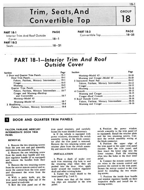
FIG. 3-<br />
.Typical Quarter <strong>Trim</strong> Water Shields<br />
R 1353.A<br />
FIG. 4- Typical Door <strong>Trim</strong> Panel <strong>and</strong> Water Shield Installation<br />
Cougar
1352-A<br />
FIG. 5. Typical Door <strong>Trim</strong> Panel <strong>and</strong> Water Shield. Mustang<br />
FIG. 6 Quarter <strong>Trim</strong> Panel Falcon, Fairlone, Mercury Intermediate
PART <strong>18</strong>-1-lnterior <strong>Trim</strong> And Roof Outside Cover <strong>18</strong>-5<br />
8. Position the arm rest <strong>and</strong> pad<br />
assembly to the panel <strong>and</strong> install the<br />
two retaining screws.<br />
COUGAR DOOR TRIM PANEL<br />
REMOVAL<br />
1. Remove the retaining screws<br />
from the window regulator h<strong>and</strong>le<br />
<strong>and</strong> the inside door h<strong>and</strong>le <strong>and</strong> remove<br />
the h<strong>and</strong>les from their shafts<br />
(Fig. 4).<br />
2. Remove the two retaining screws<br />
from the arm rest assembly <strong>and</strong> remove<br />
the assembly.<br />
3. Pry the two door pull h<strong>and</strong>le<br />
cover assemblies from the h<strong>and</strong>le <strong>and</strong><br />
remove the two retaining screws from<br />
the h<strong>and</strong>le <strong>and</strong> remove the pull h<strong>and</strong>le.<br />
4. With a putty knife, pry the<br />
trim panel retaining clips out of the<br />
inner panel <strong>and</strong> remove the panel<br />
from the door. Carefully remove the<br />
water shield, if necessary.<br />
INSTALLATION<br />
1. Place a daub of sealer over<br />
each trim retaining clip hole to seal<br />
the retaining clips when they are<br />
pushed into the door. Also, apply<br />
sealer around the window regulator<br />
shaft hole <strong>and</strong> other existing holes.<br />
2. Fasten the water shield to the<br />
inner panel (Fig. 4).<br />
3. Position the trim panel to the<br />
inner door panel <strong>and</strong> water shield<br />
<strong>and</strong> push the retaining clips into their<br />
holes.<br />
4. Position the arm rest assembly<br />
<strong>and</strong> install the two retaining screws.<br />
5. Position the inside door h<strong>and</strong>le<br />
<strong>and</strong> window regulator on their respective<br />
shafts <strong>and</strong> install the retaining<br />
screws.<br />
MUST ANG DOOR<br />
TRIM PANEL<br />
REMOVAL<br />
1. Remove the retaining screws<br />
from the window regulator h<strong>and</strong>le <strong>and</strong><br />
the inside door h<strong>and</strong>le <strong>and</strong> remove the<br />
h<strong>and</strong>les from their shafts (Fig. 5).<br />
2. Remove the two retaining screws<br />
from the arm rest assembly <strong>and</strong> remove<br />
the assembly.<br />
j. With a putty knife, pry the<br />
trim panel retaining clips out of<br />
the inner panel <strong>and</strong> remove the panel<br />
FIG. 7-Quarter <strong>Trim</strong> Panel <strong>and</strong> Water Shield-MustanQ
<strong>18</strong>-6<br />
GROUP l8-<strong>Trim</strong>, <strong>Seats</strong>, And <strong>Convertible</strong> <strong>Top</strong><br />
SECTIONAL<br />
VIEW-BB<br />
FIG. 8- Typical Quarter <strong>Trim</strong> Panel <strong>and</strong> Water Shield.<br />
Cougar<br />
R 1355-A
~<br />
from the door. Carefully remove the<br />
water shield, if necessary.<br />
INST ALLATION<br />
1. Place a daub of sealer over<br />
each trim retaining clip hole to seal<br />
the retaining clips when they are<br />
pushed into the door. Also, apply<br />
sealer around the window regulator<br />
shaft hole <strong>and</strong> other existing holes.<br />
2. Fasten the water shield to the<br />
inner panel (Fig. 5).<br />
3. Be sure that the retaining<br />
clips are installed in the trim panel.<br />
4. Position the trim panel to the<br />
inner door panel <strong>and</strong> water shield <strong>and</strong><br />
push the retaining clips into their<br />
holes.<br />
5. Position the arm rest assembly<br />
to the trim panel <strong>and</strong> install<br />
the two retaining screws.<br />
6. Place the window regulator<br />
h<strong>and</strong>le <strong>and</strong> inside door h<strong>and</strong>le on their<br />
respective shafts <strong>and</strong> install a retaining<br />
screw in each h<strong>and</strong>le.<br />
QUARTER TRIM PANEL-<br />
FALCON, FAIRLANE, MERCURY<br />
INTERMEDIATE<br />
Basically, all quarter trim panels<br />
are retained in the same manner. In<br />
view of this, one removal <strong>and</strong> installation<br />
procedure will cover all models.<br />
1. Remove the window regulator<br />
h<strong>and</strong>le <strong>and</strong> the arm rest retaining<br />
screws <strong>and</strong> remove the h<strong>and</strong>les from<br />
their shafts.<br />
2. Remove any screws retaining<br />
the trim panel to the inner panel,<br />
such as the arm rest retaining screws<br />
(Fig. 6).<br />
3. With a putty knife, pry the<br />
trim panel retaining clips out of the<br />
inner panel at each side.<br />
4. Bow the trim panel out of the<br />
retainers, <strong>and</strong> carefully loosen the<br />
wa ter shield, if necessary.<br />
5. Place a daub of sealer over<br />
each trim retaining clip hole to seal<br />
the retaining clips when they are<br />
pushed into the door. Also, apply this<br />
sealer around the window regulator<br />
shaft <strong>and</strong> other existing holes.<br />
6. Fasten the water shield to the<br />
inner panel.<br />
7. Make sure that all the retaining<br />
clips are installed in the trim<br />
panel. Place the upper edge of the<br />
trim panel in the retainer, bow the<br />
trim panel, <strong>and</strong> then insert the lower<br />
edge into the retainer. Push the retaining<br />
clips into the holes in the door<br />
inner panel (Fig. 6).<br />
8. Install the arm rest retaining<br />
screws.<br />
9. Place the friction plate against<br />
the trim panel <strong>and</strong> push the h<strong>and</strong>le<br />
onto the shaft. Install<br />
taining screws.<br />
the h<strong>and</strong>le reo<br />
COUGAR AND MUSTANG<br />
HARDTOP AND CONVERTIBLE<br />
QUARTER TRIM PANEL<br />
REMOVAl.<br />
1. Remove the rear seat cushion<br />
<strong>and</strong> the rear seat back (Refer to<br />
Part 2, Section I).<br />
2. Remove the retaining screw<br />
from the upper front trim panel cap<br />
<strong>and</strong> remove the cap, if so equipped.<br />
3. Pull the wind lace assembly<br />
from the door edge of the quarter trim<br />
panel.<br />
4. Remove the retaining screw from<br />
the quarter window regulator h<strong>and</strong>le<br />
<strong>and</strong> remove the h<strong>and</strong>le from the shaft.<br />
5. Remove the retaining screws<br />
from the trim panel <strong>and</strong> remove the<br />
panel from the inner quarter panel.<br />
6. Carefully remove the water<br />
shield, if necessary.<br />
INSTALLATION<br />
1. Place a daub of sealer over<br />
each of the retaining screw holes to<br />
seal the screw when it is installed. Also,<br />
apply sealer around the window<br />
regulator shaft hole.<br />
2. Fasten the water shield to the<br />
inner quarter panel (Fig. 7 <strong>and</strong> 8).<br />
3. Position the trim panel to the<br />
inner panel <strong>and</strong> install the retaining<br />
screws.<br />
:~<br />
UPPER FR~T<br />
Q.JARTER TRIM'<br />
PANEL.6331002<br />
."./:"<br />
i<br />
I Iii:;<br />
- ! lfi"<br />
AA~16;:;'<br />
/1;'<br />
~-::::::#'~'<br />
~.<br />
~~<br />
FIG. la-Interior<br />
Model 63<br />
UPPER FR~T QUARTER<br />
TRIM MOULDING.633 1282<br />
:/~"~i':'~'1<br />
;::~£~i:;\~<br />
4. Position the window regulator<br />
h<strong>and</strong>le on the shaft <strong>and</strong> install the<br />
retaining screw.<br />
5. Press the windlace assembly<br />
into position along the door edge of<br />
the trim panel.<br />
6. Position <strong>and</strong> install the upper<br />
trim panel cap <strong>and</strong> retaining screw,<br />
if so equipped.<br />
7. Install the rear seat back<br />
<strong>and</strong> rear seat cushion.<br />
QUARTER TRIM PANELS-<br />
MODEL 63-MUSTANG<br />
REMOVAL<br />
1. Remove the rear seat cushion.<br />
2. Tilt the rear seat back forward<br />
<strong>and</strong> remove the retaining screws<br />
from the rear floor section <strong>and</strong> remove<br />
the floor section (Fig. 9).<br />
3. Remove the two retaining bolts<br />
from the rear seat back hinges <strong>and</strong><br />
remove the seat back assembly.<br />
4; Remove the four retaining<br />
screws from the upper front quarter<br />
trim moulding <strong>and</strong> remove the moulding<br />
(Fig. 10).<br />
5. Remove the seven retaining<br />
screws from the upper front quarter<br />
trim panel <strong>and</strong> remove the panel.<br />
6. Remove the four screws retaining<br />
the rear seat latch assembly at<br />
the lower quarter panel <strong>and</strong> remove<br />
the latch assembly.<br />
7. Remove the four bolts <strong>and</strong> two<br />
screws from the lower front quarter<br />
trim panel.<br />
~~~ "-, /<br />
~§~~~~~~'i;j<br />
;,:H<br />
REAR QUARTER UPPER<br />
TR!M PANEL.6331 112<br />
~{"i,," ::==7-::~ .<br />
ki,;~~;l.;:;i)l~~t<br />
- -<br />
- LOWERR£AR<br />
--<br />
QUARTER<br />
PANEL<br />
6331222<br />
,- --<br />
LOWER FRONT BACK<br />
WINDOW TRIM PANEI-<br />
63424A68<br />
~==--<br />
~ ---<br />
TRIM<br />
--
<strong>18</strong>-8<br />
GROUP l8-<strong>Trim</strong>, <strong>Seats</strong>, And <strong>Convertible</strong> <strong>Top</strong><br />
8. Remove the carpet trim from<br />
the trim panel <strong>and</strong> disconnect the plug<br />
connectors to the courtesy light in the<br />
trim panel <strong>and</strong> remove the panel <strong>and</strong><br />
remove the li~ht from the panel.<br />
INST ALLA TIO N<br />
1. Install the courtesy light in<br />
the lower front quarter trim panel<br />
<strong>and</strong> connect the plug connectors.<br />
2. Position the trim panel to the<br />
lower quarter panel <strong>and</strong> install the<br />
retaining bolts <strong>and</strong> screws. Install<br />
the carpet trim on the trim panel.<br />
3. Position the upper front quarter<br />
trim panel <strong>and</strong> install the retaining<br />
screws.<br />
4. Position the rear seat latch<br />
assembly <strong>and</strong> install the four retainin~<br />
screws.<br />
5. Install the upper front quarter<br />
trim moulding <strong>and</strong> retaining screws.<br />
6. Position the rear seat back<br />
assembly <strong>and</strong> hinges <strong>and</strong> install the<br />
two retaining bolts in each of the<br />
hinges.<br />
7. Position the rear floor section<br />
<strong>and</strong> install the retaining screws.<br />
8. Tilt the rear seat back assembly<br />
rearward <strong>and</strong> install the rear<br />
seat back <strong>and</strong> seat cushion.<br />
HEADLINING<br />
FALCON-FAIRLANE-<br />
MERCURY INTERMEDIATE<br />
REMOVAL<br />
1. Remove the sun visors <strong>and</strong> rear<br />
view mirror.<br />
2. Remove the windshield side<br />
<strong>and</strong> upper garnish mouldings.<br />
3. Pull the door opening weatherstrips<br />
down far enough to provide access<br />
to the headlining perimeter.<br />
4. Remove the rear seat cushion<br />
<strong>and</strong> seat back.<br />
5. Remove the quarter trim<br />
panels.<br />
6. Remove the rear package tray<br />
trim panel.<br />
TRIM MOULDING-<br />
7. Remove the coat hooks <strong>and</strong> the<br />
dome light lens assemblies.<br />
8. Unhook the headlinging from<br />
the rear quarter retaining strips.<br />
9. Cut the headlining loose around<br />
the back window.<br />
10. Peel the headling from<br />
around the windshield <strong>and</strong> door openings<br />
(Figs. II, 12 <strong>and</strong> 13).<br />
11. Unhook the headlining support<br />
rods <strong>and</strong> remove the headlining<br />
assembly from the car.<br />
INSTALLATION<br />
1. Unpack <strong>and</strong> layout the new<br />
headlining.<br />
~If<br />
:"*. ~<br />
:<br />
:::;:..- :~<br />
.~...,:;,..<br />
'~rr;';,:i.<br />
III ""'o'~";"'" '.!~<br />
..~ :~'iil'r~~:.;~~<br />
REAR SUPPORT-52<strong>18</strong>0-<br />
2. Transfer the support rods from<br />
the old headlining to the new one.<br />
3. Position the headlining in the<br />
car <strong>and</strong> insert the support rod ends<br />
into their respective retaining holes<br />
in the roof side rails.<br />
4. Measure <strong>and</strong> trim excess material<br />
from the headlining around the<br />
back window.<br />
5. Apply trim cement around the<br />
back window flange <strong>and</strong> around the<br />
mating headlining edge. Tuck the<br />
headlining under the back window<br />
weatherstrip <strong>and</strong> pullout any wrinkles.<br />
6. Apply trim cement around the<br />
rear quarter area <strong>and</strong> to the mating<br />
surface of the headlining. Hook the<br />
LOWER SIDE RETAIN ER<br />
NO.3 SUPPORT (MODEL 54)-52194-5<br />
;::::(BLACK. YELLOW, MODEL 62, 52104)<br />
(GREEN. YELLOW, MODEL 54, 52103) ~'\"-: ;;~i,;,~;\,.,<br />
~--c ~'\\\ ;..'<br />
'II' 'I ~~"<br />
.,J (BRONZE- ~~LC;~,P:g;;L 62, 52105) :':/( "'~<br />
~,;<br />
SOUND ABSORBER<br />
54310<br />
=-<br />
~-~~:..,~",<br />
NO.1 SUPPORT<br />
(PURPLE. YELLOW)-52101<br />
";~}";~~~~~ (GREEN. YELLOW, NO. =- -~, MODEL 62,52103)<br />
E LLOW MO DEL 5 4 5210 5)<br />
(PINK- Y<br />
~ ~ift;!:,;'~~j~i;;<br />
, , """""" Yf<br />
A"'I'1<br />
' .,.."""... ' =-- ~<br />
HEADLINING ASSEMBLY-<br />
51916 '. ,<br />
,1)'/ ,'".:<br />
:AINER STRIP-<br />
50966<br />
~~--<br />
1~'-~- " ", .<br />
\ ~<br />
~<br />
f j - -<br />
~ :..:~<br />
SIDE REAR LOWER TACKING<br />
STRIP-50992<br />
>~:V14 C-<br />
FILLER-513A40 (GRAY-YELLOW, NO.4 SUPPORT MODEL 62, 52104) .~<br />
~ (BLACK.YELLOW, MODEL 54, 52104)<br />
~<br />
~::==::::::--<br />
\\1 (BRONZE. BRONZE, MODEL 5~, 52102)<br />
} ABSORBER-54330 ~ "' .<br />
~A~<br />
~<br />
~<br />
Rl167-B<br />
~<br />
FIG. 1<br />
Headlining Installation-Typical<br />
Mercury Intermediate, Falcon, Fairlane
REAR SOUND<br />
ABSORBER -54330<br />
SECTIONAL<br />
VIE<br />
HEADLINING ASSEMBLY<br />
, Hi . ..'<br />
C'c-<br />
--;<br />
/Il.""""".",,= 1171/ DD_~-- ~ - -. (f<br />
z."""""",~<br />
~<br />
VIEW - DD<br />
\\<br />
."<br />
CENTER SOUND<br />
ABSORBER - S4322<br />
\<br />
REAR SaUNa<br />
B -"<br />
ABSORBER - 54330<br />
C<br />
:~<br />
FRONT SOUND<br />
ABSORBER-S4310<br />
f';;:;=:<br />
N AA D<br />
. ~<br />
~ NO.3SUPPORT<br />
(BLUE. BLUE) 52103<br />
REAR SUPPO~T<br />
RETAINER-S2<strong>18</strong>0<br />
1/' IJ<br />
NO.8 SUPPORT<br />
(BLUE. GRAY) 52108<br />
SECTION~' =-=<br />
VIEW - BB ;;;o...c.<br />
NO.'5~SUPPORT<br />
. (BLUE - PURPLE) 52105<br />
NO.6 SUPPORT r<br />
, (BLUE-GREEN) 52106.~<br />
NO.7 SUPPORT ': .~<br />
(BLUE. PINK)<br />
E<br />
~<br />
N<br />
;~<br />
VIEW-EE<br />
NO.1 SUPPORT<br />
(YELLOW. PURPLE) 52101<br />
, NO.2 SUPPORT<br />
'(BRONZE, BRONZE) 52102<br />
-<br />
52107 ~~/r<br />
l ... TRIM MOULOING-<br />
SECTIONAL 03542<br />
VIEW - AA<br />
HEAD.LINING RETAINER<br />
STRIP-50966<br />
NO.4 SUPPORT<br />
:(BLUE. BROWN) 52104<br />
B-C.D.E.F<br />
ADHESIVE (C2AZ.19C52S.A:<br />
125- B<br />
FIG. 72.<br />
Headlining Installation<br />
.Typical Station Wagon<br />
FIG. 13-<br />
Headlining Installation. .Fairlane,<br />
Mercu ry Intermediate<br />
.Model 63
<strong>18</strong>-10<br />
GROUP la-<strong>Trim</strong>, <strong>Seats</strong>, And <strong>Convertible</strong> <strong>Top</strong><br />
headlining material over the retaining<br />
strips <strong>and</strong> bend the retainer tabs<br />
down.<br />
7. Apply trim cement to the roof<br />
header <strong>and</strong> to the mating surface<br />
around the front of the headlining.<br />
8. Position the headlining to the<br />
roof header <strong>and</strong> pullout any wrinkles.<br />
9. Apply trim cement around the<br />
door openings <strong>and</strong> mating surface of<br />
the headlining. Steam between the<br />
headlining panels as required to help<br />
remove any wrinkles <strong>and</strong> secure the<br />
headlining perimeter.<br />
10. <strong>Trim</strong> the excess headlining<br />
material.<br />
11. Install the package tray <strong>and</strong><br />
quarter trim panels.<br />
12. Install the coat hooks <strong>and</strong><br />
dome light lens.<br />
13. Install the windshield upper<br />
<strong>and</strong> side interior mouldings.<br />
14. Install the windlace around<br />
the door openings.<br />
15. Install the rear view mirror<br />
<strong>and</strong> sun visors.<br />
16. Install the rear seat back <strong>and</strong><br />
rear seat cushion.<br />
17. Clean the interior <strong>and</strong> headlining.<br />
MUSTANG (MODEL 63)<br />
1. Remove the sun visors <strong>and</strong> the<br />
inside rear view mirror.<br />
2. Remove the roof headlining<br />
side front retainer from each A pillar<br />
(Fig. l4-View BB).<br />
3. Remove 5 screws <strong>and</strong> remove<br />
the back window upper garnish<br />
moulding.<br />
4. Remove 4 screws <strong>and</strong> remove<br />
the quarter trim upper front mouldings<br />
<strong>and</strong> caps (Fig. 10).<br />
5. Remove 5 screws <strong>and</strong> remove<br />
the quarter trim upper front panel.<br />
6. Remove the windlace from the<br />
door openings (Fig. 14).<br />
7. Cut the headlining at the windshield<br />
weatherstrip <strong>and</strong> loosen the<br />
headlining.<br />
8. Cut the headlining at the back<br />
window weatherstrip <strong>and</strong> loosen the<br />
headlining.<br />
9. Pull the headlining from the<br />
door opening pinch weld, disconnect<br />
the bows, <strong>and</strong> remove the headlining.<br />
10. Place the old <strong>and</strong> new headlinings<br />
on a clean surface <strong>and</strong> transfer<br />
the bows to the new headlining.<br />
The bows are color coded on one<br />
end for identification (Fig. 14).<br />
11. Position the headlining in the<br />
car <strong>and</strong> install the roof bows in the<br />
side rails.<br />
12. Apply trim cement (C2AZ-<br />
19C525-A) to the back side of the<br />
headlining at the back window opening.<br />
13. Tuck the headling under the<br />
back window weatherstrip. Smooth<br />
out any wrinkles or gathering <strong>and</strong><br />
trim off any excess material.<br />
14. Apply trim cement (C2AZ-<br />
19C525-A) to the back side of the<br />
headlining at the windshield opening.<br />
15. Tuck the headlining under the<br />
windshield weatherstrip. Smooth out<br />
any wrinkles or gathering <strong>and</strong> trim<br />
off any excess material.<br />
16. Apply trim cement (C2AZ-<br />
19C525-A) to the roof side rails at<br />
the door openings. Position the headlining<br />
to the side rails <strong>and</strong> trim off<br />
any excess material (Fig. 14).<br />
17. Install the windlace in the<br />
door openings.<br />
<strong>18</strong>. Install the roof headlining side<br />
front retainer at each A pillar.<br />
19. Install the inside rear view<br />
mirror <strong>and</strong> sun visors.<br />
20. Install the right <strong>and</strong> left quarter<br />
trim upper front panels (Fig. 10).<br />
21. Install the quarter trim upper<br />
front mouldings <strong>and</strong> front caps.<br />
22. Install the back window upper<br />
garnish moulding.<br />
23. Clean all mouldings <strong>and</strong> remove<br />
any headlining scraps from the<br />
car.<br />
MUSTANG AND COUGAR<br />
(MODEL 65)<br />
The procedure for the Cougar <strong>and</strong><br />
Mustang is the same except for lights<br />
FIG. 14-Headlining Installation-Mustang Model 63
PART <strong>18</strong>-1-lnterior <strong>Trim</strong> And Roof Outside Cover<br />
<strong>18</strong>-<br />
in the roof quarters on the Cougar<br />
models.<br />
1. Remove the rear seat cushion<br />
<strong>and</strong> seat back <strong>and</strong> remove the quarter<br />
trim panels.<br />
2. Remove 2 clips <strong>and</strong> retainers<br />
<strong>and</strong> remove the package tray.<br />
3. Bend back the headlining lower<br />
rear side retaining strip tabs<br />
(Fig. 15).<br />
4. Remove the coat hanger hooks.<br />
5. Remove the sun visors.<br />
6. Remove the headlining retainer<br />
from each A pillar (Fig. 15).<br />
7. Remove 3 screws <strong>and</strong> remove<br />
the rear view mirror.<br />
8. Remove the door opening windlace<br />
from each side of the body.<br />
9. Cut the headlining along the<br />
edge of the windshield <strong>and</strong> back<br />
window weatherstrips.<br />
10. Remove the headlining from<br />
the right <strong>and</strong> left sides in the package<br />
tray area. Then, remove the headlining<br />
from the roof side rails <strong>and</strong><br />
remove it from the car.<br />
11. Place the new <strong>and</strong> old head-<br />
lining on a clean surface <strong>and</strong> transfer<br />
the headlining: upport wires in<br />
sequence to the new headlining. The<br />
roof bows are color coded on one<br />
end. When ordering new roof bows,<br />
be sure to note the color code.<br />
12. Position the headlining in the<br />
car <strong>and</strong> install the rear support wire<br />
<strong>and</strong> 2 rear support retainers. Then,<br />
install the remaining support wires,<br />
working towards the front of the car.<br />
13. <strong>Trim</strong> the headlining at the<br />
windshield header, leaving approximately<br />
1/2 inch of material for tucking<br />
under the windshield header<br />
weatherstrip.<br />
14. Apply trim cement to the<br />
windshield header <strong>and</strong>, starting from<br />
the center, cement the he&dlining to<br />
the header. Insert the remainip'J headlining<br />
material under the windshield<br />
header weatherstrip.<br />
15. <strong>Trim</strong> the headlining at the<br />
rear window, leaving approximately I /2<br />
inch of material for tucking under the<br />
weatherstrip. Apply trim cement to the<br />
rear window upper rail <strong>and</strong>, starting<br />
from the center, cementhe headlining<br />
to the upper rail. Insert the remaining<br />
material under the rear window<br />
weatherstrip.<br />
16. Pull the headlining down at<br />
the sides to remove wrinkles. Cut the<br />
listings at each end to eliminate gathering<br />
of the material.<br />
17. Apply trim cement to the left<br />
roof side rail over the door <strong>and</strong> quarter<br />
window. Pull the headlining down<br />
to remove wrinkles <strong>and</strong> cement it in<br />
place. Then, trim the headlining as<br />
necessary. Cement <strong>and</strong> trim the right<br />
side the same way.<br />
<strong>18</strong>. Straighten the metal prongs<br />
(V iew A A Fig. 15) at the package<br />
tray area; attach the headlining to<br />
the prongs <strong>and</strong> bend the prongs down<br />
as shown.<br />
19. Roll the lower rear side retaining<br />
strips into the headlining <strong>and</strong><br />
retain them by bending the tabs<br />
(V iew AA).<br />
20. Install the right <strong>and</strong> left roof<br />
side windlace at the door <strong>and</strong> windowopenings.
F () - :~ ;:<br />
<strong>18</strong>-12<br />
GROUP l8-<strong>Trim</strong>, <strong>Seats</strong>, And <strong>Convertible</strong> <strong>Top</strong><br />
21. Install the headlining retainer<br />
at the A pillar (View 00).<br />
22. Install the rear view mirror,<br />
sun visors, <strong>and</strong> coat hooks.<br />
23. Slide the package tray into position<br />
<strong>and</strong> install the retainers <strong>and</strong><br />
clips. Then, install the quarter trim<br />
panels <strong>and</strong> rear seat back <strong>and</strong> cushion.<br />
INSTRUMENT PANEL PAD<br />
FALCON, FAIRLANE, MERCURY<br />
INTERMEDIATE<br />
REMOVAL<br />
1. Open the glove box door. Remove<br />
the glove box liner retaining<br />
screws <strong>and</strong> remove the glove box<br />
liner.<br />
2. Fairlane: Remove the radio<br />
control knobs <strong>and</strong> the control shaft<br />
retaining nuts.<br />
3. Remove the instrument cluster<br />
retaining screws.<br />
4. Pull the instrument cluster out<br />
far enough to disconnect the speedometer<br />
cable, light sockets <strong>and</strong> wiring<br />
connectors from the instrument<br />
cluster. Remove the instrument<br />
cluster.<br />
5. Remove the nuts retaining the<br />
safety cover to the instrument panel.<br />
6. Pry up <strong>and</strong> remove the safety<br />
cover.<br />
INSTALLATION<br />
1. Position the new safety cover<br />
to the instrument panel (Figs. 16 <strong>and</strong><br />
17).<br />
2. Install the safety cover retaining<br />
nuts.<br />
3. Position the instrument cluster<br />
to the instrument panel. Connect<br />
the wiring connectors <strong>and</strong> the speedometer<br />
cable. Install the light sockets.<br />
4. Install the instrument cluster<br />
retaining screws.<br />
5. Fairlane: Install the radio<br />
control shaft retaining nuts <strong>and</strong> the<br />
radio control knobs.<br />
6. Position the glove box liner<br />
in place <strong>and</strong> install the glove box<br />
liner retaining screws.<br />
COUGAR INSTRUMENT<br />
PANEL PAD<br />
REMOVAL<br />
I. Disconnect the battery ground<br />
cable.<br />
2. Remove the thirteen (13) retaining<br />
screws from the front of the<br />
instrument panel pad assembly (Fig.<br />
<strong>18</strong>).<br />
3. Remove the four retaining screws<br />
from the heater control assembly <strong>and</strong><br />
position the control out of the instrument<br />
panel. Thru the heater control<br />
opening, disconnect the ~peedometer<br />
cable.<br />
4. Remove the three retaining<br />
screws from the ash receptacle <strong>and</strong><br />
disconnect the connector to the cigar<br />
lighter. Remove the receptacle assembly<br />
from the instrument panel.<br />
5. Thru the receptacle opening,<br />
remove the nut <strong>and</strong> washer retaining<br />
the inboard edge of the instrument<br />
cluster to the instrument panel.<br />
6. Remove the seven retaining<br />
screws from the instrument cluster.<br />
Position the cluster out of the panel<br />
<strong>and</strong> disconnect the windshield wiper<br />
switch, the multiple connector <strong>and</strong><br />
the push on connector to the constant<br />
voltage regulator <strong>and</strong> then remove<br />
the cluster.<br />
~<br />
PAD<br />
I ! :Y-- h<br />
~ '<br />
~:7<<br />
~", <br />
A '~~---<br />
~~;~::Z::"""'Q<br />
-:~ ~~~:<br />
. ~<br />
(I' 11" ::::::--~ .<br />
J' , ; I . '\: \<br />
i ..<br />
",+~..<br />
i i! I,<br />
. 0 "<br />
,::.;-1'<br />
1<br />
AND RETAINER<br />
ASSEMBL Y -04282<br />
" ""<br />
,<br />
';104<br />
;; :::::::::::::::::;::::::::::::::"<br />
_.-:::::::~<br />
"-~ :;<br />
]<br />
FALCON<br />
~,<br />
~ _r ' ~..:.~<br />
;;::;"'~~:::~,,::,,~ lit ~:~<br />
0 ..~.k---/~<br />
<br />
~ ,C:::~~\<br />
'<br />
, -~""'~:::=~<br />
-::::;.-<br />
._~-<br />
./-<br />
-~~/ '<br />
~:~;jJ) r' -<br />
~<br />
./~~Zij"~ ;~9- :::.' .~- -::::::---11<br />
.;.-<br />
);;;;'1<br />
FIG. 16<br />
FAIRLANE<br />
i ' :<br />
'V::;::;;:;::<br />
-~<br />
R 1261-D<br />
Instru ment Pane! Pad Installation .Falcon, Fairlane<br />
~~
~<br />
:.;;.;.; ~c,:::~<br />
"--:-<br />
r;:;:~<br />
-:--.:.~<br />
-~~"i-;~'<br />
,oP<br />
'g';;;;oo.<br />
PAD AND RETAINER<br />
04282<br />
~<br />
~<br />
"--- ~<br />
-='='1~<br />
.. ,i<br />
:;;;: 'O~~' - ..-~::::::::::::::~;;';/; ~_.,;<br />
,~<br />
_..~~<br />
(J -<br />
-<br />
;<br />
~;,;~<br />
-.-:::::: .. '<br />
:.::;;::::::... ...<br />
III'<br />
/,~~<br />
.r_~' ~ ~ -' 0<br />
::.~ ,-<br />
~ .-::::::::;.<br />
:::;"::'-"';::<br />
~- ~.-:::;<br />
& -"<br />
;;~<br />
. I<br />
FIG. 17-lnstrument Panel Pod Installation<br />
~~<br />
Mercury Intermediate<br />
~VIEW. A<br />
~-<br />
~<br />
jM~~~t!;r;;iilt[<br />
r,:;i;;:::,..~<br />
::;:;;;::;: VIEW - B<br />
c<br />
R 1158.D
<strong>18</strong>-14<br />
GROUP <strong>18</strong>-<strong>Trim</strong>, <strong>Seats</strong>, And <strong>Convertible</strong> <strong>Top</strong><br />
7. Remove the retaining screws<br />
from the glove box assembly <strong>and</strong> remove<br />
the assembly.<br />
8. Working thru the glove box<br />
opening, remove the retaining nut from<br />
the lower right end of the instrument<br />
pad.<br />
9. Remove the five screws <strong>and</strong> four<br />
nuts retaining the upper finish panel<br />
<strong>and</strong> remove the panel.<br />
10. Remove the retaining screws<br />
from the top instrument pad retainer<br />
mouldings <strong>and</strong> remove the mouldings.<br />
II. Working thru the heater control<br />
opening remove the retaining nut<br />
from the lower left end of the pad<br />
assembly.<br />
12. Pry the A pillar pad assemblies<br />
loose <strong>and</strong> remove them.<br />
13. Remove the six nuts retaining<br />
the pad assembly to the instrument<br />
panel <strong>and</strong> remove the pad assembly.<br />
INSTALLATION<br />
1. Position the pad assembly to<br />
the instrument panel <strong>and</strong> install the<br />
six retaining nuts.<br />
2. Install the lower right <strong>and</strong><br />
left nuts retaining the pad assembly<br />
to the instrument panel.<br />
3. Position the center finish<br />
panel <strong>and</strong> install five retaining screws<br />
<strong>and</strong> four nuts.<br />
4. Push the right <strong>and</strong> left A<br />
pillar pads into position to engage<br />
the retaining clips.<br />
S. Position the top instrument<br />
pad retainer mouldings <strong>and</strong> install<br />
the retaining screws.<br />
6. Insert the glove box in its<br />
opening <strong>and</strong> install the retaining<br />
screws.<br />
7. Connect the windshield wiper<br />
switch plug, the constant voltage regulator<br />
connector <strong>and</strong> the multiple<br />
connector to the instrument cluster.<br />
Position the cluster to the instrument<br />
panel <strong>and</strong> install the seven retaining<br />
screws.<br />
8. Thru the ash receptacle opening,<br />
install the inboard cluster retaining<br />
washer <strong>and</strong> nut.<br />
9. Connect the cigar lighter connector.<br />
Position the ash receptacle in<br />
the instrument panel <strong>and</strong> install the<br />
three retaining screws.<br />
10. Thru the heater control opening,<br />
connect the speedometer cable.<br />
11. Position the heater control<br />
assembly to the instrument panel <strong>and</strong><br />
install the retaining screws.<br />
12. Install the thirteen (13) retaining<br />
screws in the front of the instrument<br />
pJid assembly.<br />
13. Connect the ba ttery.<br />
MUST ANG INSTRUMENT<br />
PANEL PAD<br />
REMOVAL<br />
1. Disconnect the battery ground<br />
cable. Remove the three retaining<br />
screws from the ash receptacle assembly,<br />
<strong>and</strong> disconnect the COnneClJr to<br />
the cigar lighter.<br />
2. Remove the four screws retaining<br />
the heater control assembly to<br />
the instrument panel <strong>and</strong> position the<br />
assembly out of the panel<br />
3. Thru the heater control opening,<br />
remove the nut retaining the<br />
lower left end of the pad to the instrument<br />
panel (Fig. 19).<br />
4. Remove the five retaining screws<br />
from the instrument cluster. Thru<br />
the ash receptacle opening, remove<br />
the nut <strong>and</strong> washer retaining the inboard<br />
end of the cluster to the instrument<br />
panel Position the cluster out<br />
of the instrument panel.<br />
5. Remove the three retaining screws<br />
from the glove box assembly.<br />
6. Remove the retaining nut from<br />
the lower right end of the pad to the<br />
instrument panel<br />
7. Remove the retaining nuts from<br />
the lower, upper <strong>and</strong> center finish<br />
panels <strong>and</strong> remove the panels.<br />
8. Remove the seven screws retaining<br />
the top instrument pad retainer<br />
mouldings <strong>and</strong> remove the mouldings.<br />
9. Remove four pad retaining<br />
screws from the forward edge of the<br />
pad.<br />
10. Pull the instrument panel<br />
pad from the instrument panel.<br />
.;;t:<br />
INSTRUMENT<br />
PftNEL<br />
PAD<br />
04282<br />
~ '<br />
"<br />
,.-,--p-<br />
\,( ~<br />
FIG. 19<br />
-;;./ fJ<br />
#,VA<br />
A /;i\~:-/<br />
"<br />
r<br />
NSTAL ATION<br />
1. Position the pad to the instrument<br />
panel.<br />
2. Install the four pad retaining<br />
screws at the forward edge of the pad.<br />
3. Thru the heater control opening<br />
install the retaining nuts on the<br />
lower left of the instrument pad.<br />
4. Install the retaining nut on<br />
the lower right of the instrument pad.<br />
5. Position the center <strong>and</strong> upper<br />
fin ish panel <strong>and</strong> install the retaining<br />
screws.<br />
6. Position the lower right finish<br />
panel to the instrument panel <strong>and</strong><br />
install the retaining nut <strong>and</strong> screws.<br />
7. Position the cluster to the<br />
instrument panel <strong>and</strong> install the five<br />
retaining screws, also install the<br />
inboard cluster retaining nut <strong>and</strong><br />
washer.<br />
8. Connect the cigar lighter connector.<br />
Insert the ash receptacle assembly<br />
in the instrument panel <strong>and</strong><br />
install the three retaining screws.<br />
9. Position the heater control assembly<br />
to the instrument panel <strong>and</strong><br />
install the four retaining screws.<br />
10. Insert the glove box assembly<br />
<strong>and</strong> install the three retaining screws.<br />
11. Position the top instrument<br />
pad retainer mouldings <strong>and</strong> install<br />
the retainer screws.<br />
12. Connect the battery.<br />
PAD TOP<br />
MOOLDING ,<br />
045.22-3 SUPPORt<br />
'045C72 ---<br />
v<br />
"""F<br />
UPPER<br />
FINISH<br />
PANEL<br />
044A90<br />
Instrument Panel Pad Installation-Mustang<br />
I -LOWER<br />
~ FINISH<br />
PAN£L<br />
044A12<br />
R 1275-B
PART <strong>18</strong>-1-lnterior <strong>Trim</strong> And Roof Outside Cover <strong>18</strong>-15<br />
CONSOLE<br />
CONSOLE-MUST ANG AND<br />
COUGAR<br />
REMOV AI.<br />
I. Remove the set screw from the<br />
gear selector lever h<strong>and</strong>le <strong>and</strong> remove<br />
the h<strong>and</strong>le. Pry the top cover pad<br />
loose <strong>and</strong> remove the pad.<br />
2. Raise the door on the glove<br />
box <strong>and</strong> remove the two retaining<br />
screws from the shift lever opening covcr<br />
<strong>and</strong> remove the cover (Fig. 20).<br />
3. Remove the three screws <strong>and</strong> retainers<br />
from the dial assembly to the<br />
console.<br />
4. Remove the two screws retaining<br />
the radio to the rear support bracket.<br />
5. Remove the six screws retaining<br />
the radio <strong>and</strong> console assembly<br />
<strong>and</strong> remove the assembly. Disconnect<br />
thc antcnna wire <strong>and</strong> feed wires to<br />
tht: radio <strong>and</strong> the connector to the<br />
consolc lamp wiring.<br />
INSTALLATION<br />
I. Connect the connector to the<br />
console lamp wiring <strong>and</strong> connect the<br />
radio wiring.<br />
2. Position the radio <strong>and</strong> console<br />
assl:mbly <strong>and</strong> install thl: six retain-<br />
Ing screws.<br />
-,. Position the radio to its rear<br />
su pport bracket <strong>and</strong> install the retaining<br />
~crews.<br />
4. Install the dial assembly retainers<br />
<strong>and</strong> three retaining screws.<br />
5. Position the shift lever opening<br />
cover on the console <strong>and</strong> install<br />
the two retaining screws.<br />
6. Position the top cover pad <strong>and</strong><br />
snap the pad into place.<br />
7. Position the shift lever h<strong>and</strong>le<br />
on the shift lever <strong>and</strong> install the retaining<br />
screws.<br />
ROOF CONSOLE-COUGAR<br />
I. Remove two console attaching<br />
screws <strong>and</strong> pull the console down to<br />
unclip the two retainers (Fig. 21).<br />
2. Disconnect the wires from the<br />
console <strong>and</strong> remove the console from<br />
the vehicle.<br />
3. Position the console in the vehicle<br />
<strong>and</strong> connect the wires.<br />
4. Position the console to the roof<br />
<strong>and</strong> install the two retainers <strong>and</strong> attaching<br />
screws.
<strong>18</strong>-16<br />
GROUP l8-<strong>Trim</strong>,<br />
<strong>Seats</strong>, And <strong>Convertible</strong> <strong>Top</strong><br />
,<br />
FIG.2<br />
Couga r Roof Console<br />
ROOF OUTSIDE COVER<br />
~<br />
FALCON, FAIRLANE AND<br />
MERCURY INTERMEDIATE<br />
REMOVAL<br />
4. Remove the side <strong>and</strong> rear belt<br />
mouldings.<br />
5. Remove the back window outside<br />
mouldings. Remove the back<br />
window <strong>and</strong> weatherstrip.<br />
6. Remove the windshield wiper<br />
arm assemblies <strong>and</strong> remove the top<br />
cowl panel.<br />
7. Remove the side, top <strong>and</strong> bottom<br />
windshield outside mouldings.<br />
8. From within the vehicle remove<br />
the rear view mirror assembly,<br />
the windshield pillar cap mouldings<br />
<strong>and</strong> the plastic windshield header<br />
moulding.<br />
9. Cut the windshield sealer as<br />
described in Part 17-3 <strong>and</strong> remove<br />
the windshield.<br />
10. Remove the sealer from the<br />
windshield pinch weld flange <strong>and</strong><br />
remove the moulding retainer clips.<br />
11. Remove the drip rail moulding<br />
<strong>and</strong> then using a 0.128 to 0.132<br />
inch diameter drill, remove the rivets<br />
from the drip rail cover retainers<br />
<strong>and</strong> discard the retainers.<br />
12. Remove the staples from the<br />
front <strong>and</strong> back window opening that<br />
are retaining the cover <strong>and</strong> remove<br />
the cover from the roof.
PART <strong>18</strong>-1-lnterior <strong>Trim</strong> And Roof Outside Cover <strong>18</strong>-17<br />
FIG. 22. Typical Roof Outside Cover Installation Mercu ry Intermediate, Falcon, Fai rlane<br />
13. Remove the old adhesive from<br />
the roof area with a scraper or use<br />
an appropriate cleaning solvent. It<br />
is extremely important that the entire<br />
roof <strong>and</strong> drip rails are thoroughly<br />
cleaned.<br />
INSTALLATION<br />
It is recommended that drive nails<br />
be substituted for the staples shown<br />
in Fig. 22.<br />
Wherever possible, use the existing<br />
drive nail or screw holes. Therefore,<br />
each location should be identified<br />
on the pinch weld flange with<br />
a wax crayon.<br />
Seal all unused holes with either<br />
CIAZ-19627-A Pressure Sensitized<br />
Tape or AB-19560-A caulking cord.<br />
1. Carefully position the outside<br />
cover on the roof panel. (Fore <strong>and</strong><br />
Aft center punch marks have been<br />
provided in the cover for centering<br />
purposes.)<br />
2. With the cover properly positioned<br />
<strong>and</strong> temporarily secured, apply<br />
an even coating of C2AZ-19C-<br />
525-A adhesive to the roof panel <strong>and</strong><br />
a like amount to the corresponding<br />
area of the roof outside cover assembly.<br />
For best results, secure limited<br />
sections at a time. Make certain<br />
that the adhesiye is not lumpy as it<br />
will be objectionable from an appearance<br />
stdndpoint.<br />
3. Using a 0.128 to 0.132 inch<br />
diameter drill, pierce the vinyl material<br />
at the existing staple or screw<br />
hole locations. Install drive nails in<br />
each of the holes.<br />
4. Position both drip rail re.tainers<br />
<strong>and</strong>, using the same drill referred to<br />
above, pierce the vinyl at each of<br />
the holes. Install the Pop rivets from<br />
the underside of the drip rail except<br />
at the extreme rear hole in which<br />
case the rivet should be inserted from<br />
the retainer side.<br />
5. <strong>Trim</strong> the excess cover material<br />
from around the entire perimeter.<br />
6. Apply sealer C3AZ-19562-A<br />
(for white tops) or sealer C3AZ-<br />
19562-B (for black tops) over the<br />
entire surface of the drip rail retainers.<br />
With the drip rail properly<br />
sealed, a minimum depth of 1/8 inch<br />
should be retained for adequate<br />
water drainage. Place masking tape<br />
on the cover assembly for the entire<br />
length of the drip rail before applying<br />
sealer. After sealer has been applied,<br />
remove the tape.<br />
7. Install the drip rail mouldings.<br />
8. Install the back belt center <strong>and</strong><br />
side mouldings.<br />
9. Reposition <strong>and</strong> secure the headlining.<br />
10. Install the back window <strong>and</strong><br />
outside window mouldings.<br />
II. Install the quarter trim panel<br />
retainer mouldings <strong>and</strong> quarter window<br />
garnish mouldings.<br />
12. Install the package tray panel,<br />
quarter panels, rear seat back <strong>and</strong><br />
seat cushion.<br />
13. Install the windshield.<br />
14. Install the windshield interior<br />
garnish mouldings <strong>and</strong> sun visor assemblies.<br />
15. Install the windshield exterior<br />
mouldings, retainers, <strong>and</strong> windshield<br />
wiper blade assemblies.<br />
ROOF OUTSIDE COVER-<br />
MUSTANG AND COUGAR<br />
REMOVAL<br />
1. Disconnect the battery negative<br />
cable. At this time also unpack <strong>and</strong><br />
spread out the roof cover.<br />
2. Re!:l1°ve the windshield wiper<br />
arms. Also remove the windshield exterior<br />
mouldings using tool T64P-<br />
420068 orC (Refer to Part 17-3).<br />
3. Remove the rear seat cushion<br />
<strong>and</strong> rear seat back.<br />
4. Remove the five retaining screws<br />
from each of the quarter trim panels<br />
<strong>and</strong> remove the panels.
<strong>18</strong>-<strong>18</strong> GROUP l8-<strong>Trim</strong>, <strong>Seats</strong>, And <strong>Convertible</strong> <strong>Top</strong><br />
FIG. 23<br />
Outside Roof Cover Installation<br />
Mustang<br />
SECTIONAL<br />
VIEW-AA<br />
SECT I!<br />
R 1361-A<br />
~<br />
FIG. 24 Outside Roof Cover Installation Cougar
PART <strong>18</strong>-1-lnterior <strong>Trim</strong> And Roof Outside Cover <strong>18</strong>-19<br />
5. On the Mustang only, loosen<br />
the headlining at the roof quarters.<br />
6. Remove the retaining nuts from<br />
the right <strong>and</strong> left h<strong>and</strong> back side belt<br />
mouldings <strong>and</strong> remove the mouldings.<br />
Also the back belt moulding below<br />
the rear window on the Cougar<br />
(Figs. 23 <strong>and</strong> 24).<br />
7. Remove the exterior moulding<br />
from around the rear window with tool<br />
T64P-42006-B or C.<br />
8. Remove the moulding retainers<br />
from around the windshield <strong>and</strong> rear<br />
window.<br />
9. Remove the left <strong>and</strong> right roof<br />
side drip rail mouldings.<br />
10. On the Cougar only, remove<br />
the right <strong>and</strong> left weatherstrips <strong>and</strong><br />
remove the ten retaining screws from<br />
each of the weatherstrip retainers<br />
<strong>and</strong> remove the retainers. Also remove<br />
the four rivets from each of the<br />
drip rail moulding extensions <strong>and</strong> remove<br />
the extensions (Fig. 25).<br />
11. Remove the rivets retaining<br />
the right <strong>and</strong> left drip rail retainers<br />
<strong>and</strong> remove the retainers. The rivets<br />
may be drilled out with a 0.128 to<br />
0.132 diameter drill.<br />
12. Clean all mouldings <strong>and</strong> retainers<br />
<strong>and</strong> clean the excess sealer<br />
at the windshield <strong>and</strong> rear window.<br />
13. Remove the outside roof cover,<br />
leaving the staples in place. Remove<br />
the old adhesive from the roof area<br />
with a scraper or appropriate clean-<br />
ing solvent. It is extremely important<br />
that the entire roof <strong>and</strong> drip rail are<br />
thoroughly cleaned.<br />
INSTALLATION<br />
It is necessary that drive nails<br />
be substituted during installation<br />
for the staples.<br />
Seal all unused holes <strong>and</strong> staples<br />
with sealer AB-19560A.<br />
1. Locate the center line on the<br />
roof cover using the center punch<br />
marks that have been provided in the<br />
cover for this purpose. Also mark<br />
the center line of the roof to allow<br />
for proper alignment of the roof<br />
cover.<br />
2. Apply Vinyl Roof Adhesive<br />
C5AZ-19C525-A to one half of the<br />
roof <strong>and</strong> the corresponding half of the<br />
roof cover, from the center line to the<br />
seam. Make certain that the adhesive<br />
is not lumpy as it will be objectionable<br />
from an appearance<br />
st<strong>and</strong>point.<br />
3. Carefully align the center<br />
lines of the roof cover <strong>and</strong> roof.<br />
Then stretch <strong>and</strong> smooth the roof cover<br />
into position.<br />
4. Apply adhesive to the remaining<br />
part of the roof <strong>and</strong> the corresponding<br />
roof cover <strong>and</strong> install the<br />
cover as outlined in the preceeding<br />
step.<br />
5. Apply adhesive to the remain-<br />
ing parts of the roof <strong>and</strong> roof cover,<br />
except the window opening.<br />
6. Position the remaining parts<br />
of the roof cover to the roof sides<br />
<strong>and</strong> roof quarters, stretch <strong>and</strong> smooth<br />
as necessary. <strong>Trim</strong> or make any<br />
angular cuts in the roof cover around<br />
the window openings. On the .cougar<br />
only; start below the rear window.<br />
7. <strong>Trim</strong> all selvage from the cover,<br />
leaving about 1/2 inch around the<br />
window openings.<br />
8. Apply adhesive to the front<br />
pillars <strong>and</strong> position the cover.<br />
9. Apply adhesive to the window<br />
opening areas <strong>and</strong> stretch the cover<br />
into position. Cut the cover from<br />
around the moulding retainer studs.<br />
10. Using an awl, pierce the roof<br />
cover at intervals of 1 1/2 inches<br />
around the window openings. Install<br />
the drive nails in each of the holes<br />
in the roof cover. Be sure to apply<br />
sealer to each of the nails before<br />
they are installed. Also take precautions<br />
to protect the window glass<br />
during this operation.<br />
II. Position both drip rail retainers<br />
<strong>and</strong>, with the awl pierce the<br />
roof cover at each of the holes. Insta<br />
II the seventeen (17) retain ing<br />
rivets in the retainers. On the Cougar<br />
it is also necessary to install four<br />
rivets in the drip moulding extensions.<br />
12. Install the right <strong>and</strong> left<br />
h<strong>and</strong> drip rail mouldings.<br />
VIEW-A<br />
.~~<br />
ADHESIVE<br />
~ A<br />
J VIEW-B VIEW-C R 1372.A<br />
/<br />
/'<br />
/<br />
0<br />
FIG. 25<br />
Roof Side Rail Weatherstrip Installation-Cougar
<strong>18</strong>~20 GROUP l8-<strong>Trim</strong>, <strong>Seats</strong>, And <strong>Convertible</strong> <strong>Top</strong><br />
13. On the Cougar only; install<br />
the weatherstrips <strong>and</strong> the weatherstrip<br />
retainers shown in Fig. 25.<br />
14. Install the exterior window<br />
moulding retainers around the windshield<br />
<strong>and</strong> rear window. Also apply<br />
sealer AB-19560A around the windshield<br />
<strong>and</strong> rear window.<br />
15. Position <strong>and</strong> install the wind-<br />
shield <strong>and</strong> rear window exterior<br />
mouldings.<br />
16. On the Cougar only; install<br />
the back belt mouldings <strong>and</strong> nine retaining<br />
nuts below the rear window.<br />
17. Install the back side belt<br />
mouldings <strong>and</strong> the retaining nuts.<br />
<strong>18</strong>. On the Mustang only; install<br />
the headlining at the roof quarters.<br />
19. Position <strong>and</strong> install the quarter<br />
trim panels <strong>and</strong> install the rear<br />
seat back <strong>and</strong> seat cushion.<br />
20. Install the windshield wipers<br />
<strong>and</strong> thoroughly clean the cover <strong>and</strong><br />
moulding areas.<br />
21. Connect the battery negative<br />
cable.
1 St<strong>and</strong>ard Seat Removal <strong>and</strong> <strong>Seats</strong><br />
<strong>and</strong> Seat Installation Track<br />
Rear Front Seat Seat Seat Back Cushion Cushion Back Cover Cover<br />
Cover Cover<br />
Removal <strong>and</strong> Installation<br />
<strong>18</strong>-21<br />
Section<br />
Front Seat Cushion <strong>and</strong>/or Back<br />
Rear Seat Cushion <strong>and</strong>/or Back.<br />
2 Bucket <strong>Seats</strong>-Manual ,<br />
Page<br />
<strong>18</strong>-21<br />
<strong>18</strong>-21<br />
<strong>18</strong>-21<br />
,<strong>18</strong>-22<br />
,<strong>18</strong>-22<br />
<strong>18</strong>-22<br />
,<strong>18</strong>-22<br />
,<strong>18</strong>-23<br />
<strong>18</strong>-22<br />
.<strong>18</strong>-26<br />
.<strong>18</strong>-26<br />
Section<br />
Seat Front <strong>and</strong> Seat Cushion Track Cover<br />
3 Power Front Removal <strong>Seats</strong> Seat <strong>and</strong> Back Installation.<br />
Cover<br />
Bucket Bench Seat Seat Track Motor Track<br />
4 Seat Belts <strong>and</strong> Shoulder Straps<br />
Removal <strong>and</strong> Installation ,<br />
Page<br />
<strong>18</strong>-26<br />
<strong>18</strong>-26<br />
<strong>18</strong>-27<br />
<strong>18</strong>-30<br />
<strong>18</strong>-30<br />
,<strong>18</strong>-30<br />
,<strong>18</strong>-30<br />
<strong>18</strong>-31<br />
<strong>18</strong>-31<br />
<strong>18</strong>-31<br />
STANDARD SEATS<br />
REMOVAL<br />
AND INSTAllATION<br />
SEAT AND SEAT TRACK<br />
Work, other than that of minor<br />
na ture, is more easily performed<br />
when the front seat assembly is removed<br />
from the car.<br />
I. Remove the nuts retaining the<br />
seat tracks to the floor pan. If<br />
equipped with power seats, discon-<br />
nect the seat wiring loom connector.<br />
Lift the seat assembly from the car<br />
(Figs. I <strong>and</strong> 2).<br />
2. Disconnect <strong>and</strong> remove the release<br />
cable from the seat frame.<br />
Remove the seat tracks from the seat<br />
frame.<br />
J. Transfer the seat adjusting lever<br />
knob <strong>and</strong> the retracting springs,<br />
if necessary, to the new track assembly.<br />
4. Position the seat tracks on the<br />
seat frame <strong>and</strong> install the retaining<br />
bolts <strong>and</strong> release cable.<br />
5. Position the seat assembly in<br />
the car <strong>and</strong> install the retaining bolts<br />
<strong>and</strong> nuts.<br />
Release Cable Adjustment. Release<br />
cable maladjustment will affect<br />
only the right side of the seat. In<br />
case the latch retaining the track<br />
fails to release, turn the release cable<br />
OJSHIO'j ASSEMBLY
turnbuckle or eye bolt enough turns<br />
to shorten the release cable travel<br />
sufficiently to release the track latch.<br />
If the latch fails to secure the seat<br />
travel, turn the release cable turnbuckle<br />
or eye bolt to lengthen the<br />
release cable enough to allow the<br />
latch to snap in the locking position.<br />
FRONT SEAT CUSHION<br />
AND/OR BACK<br />
1. Remove the front seat <strong>and</strong> seat<br />
track from the car if the cushion is to<br />
be replaced.<br />
2. To replace the seat cushion, remove<br />
the seat assembly from the seat<br />
track.<br />
3. On cars with a solid seat back,<br />
remove the bolts <strong>and</strong> washers attaching<br />
the seat back to the seat<br />
cushion frame. Before being able to<br />
remove the attaching bolts it is necessary<br />
to remove the seat back <strong>and</strong><br />
seat cushion trim from the bolts.<br />
4. On cars with a split front seat<br />
back, remove the hairpin clip from<br />
the center seat back stud <strong>and</strong> the<br />
seat cushion stud. Before being able<br />
to remove the hair pin clips it is<br />
necessary to remove the pivot covers.<br />
5. Position the seat back assembly<br />
on the seat. On cars with the<br />
split seat back, install the hairpin<br />
clip at the seat center bracket <strong>and</strong><br />
the seat cushion stud <strong>and</strong> install<br />
the pivot covers.<br />
6. On a car with a solid seat back,<br />
install the bolts <strong>and</strong> washers attaching<br />
the seat back to the seat <strong>and</strong> fasten<br />
the seat back <strong>and</strong> seat cushion<br />
cover trim with hog rings.<br />
7. Position the seat cushion on the<br />
seat track <strong>and</strong> install the retaining<br />
bolts if removed.<br />
8. Install the front seat <strong>and</strong> seat<br />
track in the car.<br />
REAR SEAT CUSHION<br />
AND/OR BACK<br />
1. Lift the rear seat cushion <strong>and</strong><br />
pull it forward to remove it from the<br />
car.<br />
2. Remove one rear seat arm rest<br />
(two-door sedans).<br />
3. Remove 2 rear seat back attaching<br />
screws located at the bottom of<br />
the seat back. On the Mustang Model<br />
63 there are four screws retaining the<br />
seat along the bottom.<br />
4. Lift up on the seat back to disengage<br />
the seat from the upper hooks<br />
<strong>and</strong> remove the seat back from the<br />
car.<br />
5. Position the seat back in the car<br />
<strong>and</strong> engage the seat with the upper<br />
hooks.<br />
6. Install the seat back lower retaining<br />
screws <strong>and</strong> the removed arm<br />
rest. Then install the rear seat cushion.<br />
FRONT SEAT CUSHION<br />
COVER<br />
Figs. 3 <strong>and</strong> 4 show a front seat<br />
cushion buildup. Seat cushions for all<br />
models are built up in basically the<br />
same manner. Therefore, when installing<br />
new seat cushion covers or<br />
pads, refer to Figs. 3 <strong>and</strong> 4 for the<br />
location of listing wires, hog rings,<br />
anti-squeak pads, <strong>and</strong> seat pad stackup.<br />
1. Remove the seat <strong>and</strong> seat track<br />
assembly.<br />
2. On models with a solid seat<br />
back, remove the bolts <strong>and</strong> washers<br />
attaching the seat back to the seat<br />
cushion frame.<br />
3. On models with a split seat<br />
back, remove the seat back outer<br />
support arm covers <strong>and</strong> remove the<br />
hairpin clips from the pivot pins.<br />
4. On models with a split seat<br />
back, remove the retaining screw<br />
from the seat back center support<br />
trim cover <strong>and</strong> remove the seat back<br />
center pivot hair pin clips.<br />
5. Remove the seat back assembly.<br />
6. Remove the seat back stop<br />
plates from the seat cushion.<br />
7. Remove the hog rings retaining<br />
FIG. 2 ypical Front Seat Track Installation-Mustang, Cougar
PART <strong>18</strong>-2-<strong>Seats</strong><br />
<strong>18</strong>-23<br />
the seat cushion cover <strong>and</strong> remove<br />
the cover (Figs. 2 <strong>and</strong> 3). Inspect the<br />
pad <strong>and</strong> replace it if necessary.<br />
8. Transfer the listing wires to the<br />
new cover.<br />
9. With the seat cushion assembly<br />
right side up, make sure that the pads<br />
are stacked properly <strong>and</strong> centered;<br />
then place the cover over the pads to<br />
hold them in position.<br />
10. Carefully turn the seat assembly<br />
over so that the pads do not shift<br />
out of position.<br />
II. After centering the cover <strong>and</strong><br />
straightening the seams along the<br />
front edge of the cushion, fasten the<br />
cover to the front of the seat frame<br />
with hog rings. Make sure that the<br />
hog rings encircle the listing wire. Install<br />
I hog ring in each hole provided<br />
in the seat cushion frame.<br />
12. At the rear of the seat assembly,<br />
pull the cover taut over the<br />
pads, <strong>and</strong> install hog rings at the<br />
seat frame.<br />
13. Fasten the side of the cover<br />
to the seat frame side with hog rings<br />
through the holes provided (Figs. 2<br />
<strong>and</strong> 3).<br />
14. Install the seat back stop<br />
plates <strong>and</strong> the seat back.<br />
15. Install the seat tracks to the<br />
cushion <strong>and</strong> the seat assembly in the<br />
car.<br />
REAR SEAT CUSHION<br />
COVER<br />
1. Remove the rear seat cushion<br />
from the car by lifting on the front of<br />
the seat <strong>and</strong> pulling it forward.<br />
2. Remove the cushion cover hog<br />
rings <strong>and</strong> remove the cushion cover<br />
from the seat frame.<br />
3. Inspect the pad <strong>and</strong> replace it<br />
if necessary.<br />
4. Transfer the listing wire, if<br />
equipped, to the new cushion cover.<br />
5, Position the new cushion cover<br />
on the seat frame <strong>and</strong> springs <strong>and</strong> attach<br />
it in place with hog rings (Fig. 5).<br />
R 1164-C<br />
FIG. 3- Tvoical Front Seat Cushion Cover Installation-Falcon.<br />
Fairlane. Mercury Intermediate
<strong>18</strong>-24 GROUP l8-<strong>Trim</strong>, <strong>Seats</strong>, And <strong>Convertible</strong> <strong>Top</strong><br />
FIG. 4. Front Seat Cover Installation -Mustang, Cougar<br />
FIG.5 .TVDical Rear Seat CushiDn Cnv~r In~tnllntinn
<strong>18</strong>-26 GROUP l8-<strong>Trim</strong>, <strong>Seats</strong>, And <strong>Convertible</strong> <strong>Top</strong><br />
FIG. 8.<br />
Typical Rear Seat Back Cover Installation<br />
1262<br />
BUCKET SEATS-MANUAL<br />
The seat is mounted in the conventional<br />
manner on two seat tracks.<br />
The seat release is located at the<br />
lower front center of the seat, <strong>and</strong> is<br />
operated by pulling the lever side<br />
ways to release the seat tracks.<br />
REMOVAL<br />
SEAT AND SEA'<br />
AND INSTAllATION<br />
TRACK<br />
The seat track assembly is easily<br />
replaced if the seat assembly is removed<br />
from the car.<br />
1. Remove 4 floor pan plug buttons<br />
to gain access to the seat track<br />
retaining nuts (Mustang <strong>and</strong> Cougar<br />
only).<br />
2. From under the car. remove<br />
the seat track retaining stud nuts <strong>and</strong><br />
washers. Remove the seat assembly<br />
from the car <strong>and</strong> place it on a clean<br />
work area.<br />
3. Remove the screws which retain<br />
the seat track assembly to the<br />
seat cushion <strong>and</strong> remove the seat<br />
track assembly (Figs. 9 <strong>and</strong> 10).<br />
4. Disconnect the seat track brace<br />
<strong>and</strong> latch release rod from the track<br />
being replaced, <strong>and</strong> connect these<br />
parts to the new seat track.<br />
5. Loosely install the track-to-floor<br />
retaining studs in the seat track.<br />
6. Place the seat track assembly<br />
on the seat cushion, <strong>and</strong> install the<br />
retaining screws.<br />
7. Place the seat assembly in the<br />
car <strong>and</strong> install the washers <strong>and</strong> nuts<br />
on the retaining studs.<br />
8. Install the floor pan plug buttons<br />
(Mustang <strong>and</strong> Cougar only).<br />
FRONT SEAT CUSHION<br />
COVER<br />
Repairs to se~t cushions or seat<br />
backs are performed out of the car<br />
<strong>and</strong> are usually limited to replacement<br />
of torn or burned seat covers.<br />
In a few instances, the pads may be<br />
damaged <strong>and</strong> require replacement.<br />
When installing a new seat cover<br />
or pad, refer to Figs. II <strong>and</strong> 12 for<br />
the location of listing wires, hog<br />
rings, anti-squeak pads, <strong>and</strong> seat pad<br />
stack-up.<br />
Mercury Intermediate, Falcon<br />
(Model 76 Only)<br />
Remove the seat <strong>and</strong> seat track<br />
assembly from the car <strong>and</strong> place it<br />
on a clean work area.<br />
2~ Remove the seat cushion from<br />
the seat track. From each side of the<br />
seat, remove the seat back retainer,<br />
<strong>and</strong> remove the seat back.<br />
3. Remove the seat back scuff<br />
plates <strong>and</strong> remove the hog rings retaining<br />
the seat cushion cover to the<br />
spring assembly. Separate the bottom<br />
cover from the seat cushion pad <strong>and</strong><br />
remove the cushion cover.<br />
4. Inspect the pad <strong>and</strong> spring assemblies,<br />
<strong>and</strong> repair or replace as<br />
necessary.<br />
5. Transfer the listing wires to the<br />
new cover.<br />
6. Place the new cover assembly<br />
over the pad <strong>and</strong> seat spring assembly<br />
<strong>and</strong> secure it to the front bolster<br />
wire with hog rings. Apply trim<br />
cement (C2AZ-19C525-A) to the<br />
bottom of the cushion cover <strong>and</strong><br />
position the cover correctly to the<br />
seat cushion pad.<br />
7. Secure each side bolster wire<br />
t the seat spring assembly with hog<br />
rIngs.<br />
8. The front <strong>and</strong> side edges of the<br />
cover assembly can now be secured<br />
to the bottom of the spring assembly<br />
with hog rings as shown in Fig. II.
PART <strong>18</strong>-2-<strong>Seats</strong><br />
1 8-27<br />
9. Sec.ure the rear edge of the<br />
cover assembly to the bottom of the<br />
spring assembly with hog rings.<br />
10. Install the two scuff plates on<br />
the cushion.<br />
II. Install the seat back side<br />
shield <strong>and</strong> seat tracks. Install the<br />
seat assembly.<br />
Mustang <strong>and</strong> Cougar<br />
1. Remove the front seat <strong>and</strong> track<br />
from the car <strong>and</strong> remove the seat<br />
tracks from the seat.<br />
2. Remove the front seat back<br />
shield <strong>and</strong> the seat back pivot side<br />
cover.<br />
3. Remove the ~eat back pivot pin<br />
<strong>and</strong> remove the seat back from the<br />
seat cushion.<br />
4. Remove the seat cushion scuff<br />
plate.<br />
5. Remove the seat cushion cover<br />
<strong>and</strong> pad.<br />
6. Position the seat cushion pad on<br />
the frame <strong>and</strong> install the hog rings<br />
(Fig. 12).<br />
7. Position the cushion cover on<br />
the pad. Cement with trim cement<br />
(C2AZ-19C525-A) <strong>and</strong> retain with<br />
hog rings (Fig. 12).<br />
8. Install the seat cushion scuff<br />
plate.<br />
9. Position the seat back on the<br />
pivot <strong>and</strong> install the pivot pin.<br />
10. Install the front seat back<br />
shield <strong>and</strong> the seat back pivot side<br />
cover.<br />
11. Install the seat on the seat<br />
tracks <strong>and</strong> install the seat <strong>and</strong> seat<br />
track in the car.<br />
FIG. 9- Bucket Seat Installation. Falcon, Fairlane, Mercury Intermediate<br />
FRON'<br />
SEAT BACK COVER<br />
1. Remove the seat <strong>and</strong> seat<br />
tracks from the car, if required, for<br />
accessibility to the seat side shield<br />
retaining screws.<br />
2. Remove the right <strong>and</strong> left seat<br />
back side shields <strong>and</strong> remove the seat<br />
back retaining bolts or retainer pins<br />
<strong>and</strong> remove the seat back from the<br />
cushion.<br />
3. Unsnap <strong>and</strong> remove the seat<br />
back rear cover (Figs. II <strong>and</strong> 12).<br />
4. Remove the seat back upper<br />
moulding retaining screws <strong>and</strong> remove<br />
the mouldings.<br />
5. Remove the seat back stop adjusting<br />
bolts <strong>and</strong> remove the hog<br />
rings retaining the cover to the<br />
frame.<br />
6. Bend up the side retaining tabs<br />
(Fig. II) <strong>and</strong> lift the cover off the<br />
tabs.<br />
7. Remove any additional hog<br />
rings retaining the cover to the seat<br />
frame.<br />
8. Position the trim cover off the<br />
side padding to gain access to the FIG. 10- Bucket Seat Installation. Mustang, Cougar<br />
R 1366.A
<strong>18</strong>-28<br />
GROUP l8-<strong>Trim</strong>, <strong>Seats</strong>, And <strong>Convertible</strong> <strong>Top</strong><br />
cr<br />
A HOG RINV(16 REQ'O)<br />
B HOG RING (3 REQ'O EACH BOLSTER)<br />
C HOG RING (6 REQ'O EACH BOLSTER)<br />
0 HOG RING (5 REQ'O)<br />
E HOG RING (7 REQ'O)<br />
F HOG RING (5 REQ'O ALONG REAO)<br />
G ADHESIVE-C2AZ. 19C52S- A<br />
FIG. 1<br />
Tvcical Bucket Seat Back <strong>and</strong> Cushion Cover Installation-Mercury Intermediate, Falcon, Fairlane
PART <strong>18</strong>-2-<strong>Seats</strong><br />
<strong>18</strong>-29<br />
A<br />
C<br />
\<br />
JUTE<br />
BO~STERWIRE<br />
65446<br />
PAD ASSEMBLY -<br />
64819<br />
CDYER ASSEMBLY..<br />
64416<br />
-J<br />
ANTI-SQUEAK"..,<br />
B~ .-<br />
~<br />
,~<br />
COVER ASSEMBLY-<br />
64416<br />
"".<br />
l.<br />
M<br />
.--" .~ /<br />
;;;..;~::::::<br />
~K-':":___:<br />
REAR TRIM<br />
PANEL COVER<br />
--.:===:-<br />
REAR PANEL. CL;~~"'-:.<br />
(11 REQ'D) f"-i,~<br />
E ---~~\..<br />
--'-- -= -<br />
/'<br />
/<br />
:J>1<br />
~<br />
REAR TRIM PANEL<br />
PAD-64625<br />
,<br />
" I..<br />
:'/~<br />
:/ ~<br />
REAR TRIM<br />
- PANEL -61632<br />
:--- ..<br />
'<br />
-~~~ / ci~r"<br />
/' '~~j) '.<br />
./<br />
,/ /l~<br />
, SPRING ASSEMBLY-<br />
64700-)<br />
/~~ , "J1:J:<br />
~)<br />
A<br />
B<br />
C<br />
D<br />
E<br />
F<br />
G<br />
K<br />
HOG RING (19 REQ'D)<br />
HOG RING (3 REQ'D)<br />
HOG RING (5~EQ'D)<br />
HOG RING (17 REQ'D)<br />
HOG RING (5 REQ'D)<br />
HOG RING (12 REQ'D)<br />
HOG RING (5 REQ'D)<br />
ADHESIVE C2AZ- 19C525- A<br />
SPRING ASSEMBLY<br />
64700-1<br />
J<br />
-<br />
'F-f-'<br />
SCUFF PLATE-<br />
61643<br />
--<br />
- ~<br />
'J.~B~<br />
A HOG RING (15 REQ'D)<br />
C HOG RING (12 REQ'D)<br />
B HOG RING (4 REQ'D)<br />
E HOG RING (5 REQ'D)<br />
F HOG RING (12 REQ'D)<br />
G HOG RING (4 REQ'D)<br />
Ii ADHESIVE -C2AZ. ~9E:525.A<br />
-"'-" ..:-;--'t~..1 ~<br />
--~ '~<br />
'/ PAD ASSEMBL<br />
c Y -""..., ","<br />
-- ~,\<br />
~B -~-r;:-<br />
- D<br />
BOLSTER WIRE- -"~<br />
65447<br />
AN~~:~UEA~" ~-~<br />
c'<br />
63222 ~<br />
( -.-;!/,<br />
'<br />
C"'-',-,;:<br />
~~~~~~::=:~ -<br />
-COVER ASSEMBL Y -<br />
'~;<br />
62900<br />
BOLSTER WIRE- ~~~=--<br />
631AO8<br />
'SPRING ASSEMBLY<br />
D<br />
63100.]<br />
//~<br />
FRONT WIRE-<br />
~ 66691<br />
--"'"<br />
,,~<br />
~<br />
/<br />
..Eh-~~~~<br />
-:::;;~~'\<br />
~~~c,~.<br />
A<br />
f<br />
c,£"~~~~ :"'~~<br />
:::~<br />
t<br />
"'"<br />
1 8-30 GROUP l8-<strong>Trim</strong>, <strong>Seats</strong>, And <strong>Convertible</strong> <strong>Top</strong><br />
hog rings in the center of the seat<br />
back <strong>and</strong> remove the hog rings.<br />
9. Position the new cov~r over the<br />
front center of the seat back <strong>and</strong> attach<br />
it with hog rings. Position the<br />
cover around the sides <strong>and</strong> top of<br />
the sponge padding, pulling the material<br />
tight. Then, turn the seat back<br />
face down.<br />
10. Pull the trim cover tight <strong>and</strong><br />
install hog rings at the top. Pull the<br />
cover tight <strong>and</strong> install hog rings at<br />
the bottom.<br />
11. Pull the trim cover tight at the<br />
sides <strong>and</strong> position it over the side<br />
retaining tabs (Fig. 11). Bend the<br />
tabs down.<br />
12. Position the rear cover on the<br />
seat back <strong>and</strong> snap it into place. Install<br />
the seat back stop adjusting bolts<br />
<strong>and</strong> nuts.<br />
13. Install the seat back upper<br />
moulding.<br />
14. Install the seat back on the<br />
cushion <strong>and</strong> install the seat back pivot<br />
covers.<br />
15. Install the seat <strong>and</strong> seat track<br />
in the car.<br />
POWER SEATS<br />
REMOVAL<br />
AND INSTALLATION<br />
BENCH SEAT TRACK-POWER<br />
-MERCURY INTERMEDIATE<br />
Removal<br />
SCREW AND WASHER<br />
370385-52<br />
CUSHION~""""'U'-'<br />
1. Remove the retaining bolts<br />
from the two inboard seat belts at<br />
the tunnel.<br />
2. Remove the four seat track retaining<br />
nuts. Disconnect the seat wiring<br />
loom at the quick disconnect <strong>and</strong><br />
remove the seat assembly from the<br />
vehicle. (Fig. 13).<br />
3. Remove the four retaining<br />
screws from the cushion assembly to<br />
the seat track.<br />
4. Disconnect the wires leading<br />
from the seat control switch assembly<br />
at the quick disconnect <strong>and</strong> separate<br />
the cushion assembly from the seat<br />
track.<br />
5. Release the tension on the assist<br />
springs on the seat track assembly.<br />
6. Remove the six screws retaining<br />
the three drive units to the track<br />
assembly <strong>and</strong> separate the units from<br />
the track.<br />
7. Remove the relays from their<br />
brackets.<br />
8. Remove the two nuts retaining<br />
the motor to its bracket <strong>and</strong> remove<br />
the motor.<br />
9. Remove the two screws retaining<br />
the transmission assembly to its<br />
bracket <strong>and</strong> disconnect the wires to<br />
the transmission <strong>and</strong> remove the<br />
transmission.<br />
Installation<br />
1. Position the transmission assembly<br />
to its seat track bracket <strong>and</strong><br />
install the two retaining screws.<br />
Connect the wires at the quick disconnect.<br />
2. Position the motor to its<br />
bracket <strong>and</strong> install the two retaining<br />
nuts.<br />
3. Position three drive units on<br />
the seat track assembly <strong>and</strong> install<br />
the six retainin~ Screws.<br />
~ ~c<br />
~<br />
~ ,,:<br />
.£-:: ""-<br />
NUT AND W<br />
376785-52 ~- -, ASSEMBLY-6170'<br />
~ )" -:" ~ ~'h ~' c<br />
BENCH SEAT<br />
3 WAY POWER ./<br />
FIG. 13-Power Seat Track-Bench<br />
4. Install the relays in their<br />
brackets.<br />
5. Install the assist springs on<br />
the seat tracks.<br />
6. Connect the control switch<br />
quick disconnect <strong>and</strong> position the<br />
cushion assembly to the seat track<br />
<strong>and</strong> install the four retaining screws.<br />
7. Place the assembled seat in the<br />
vehicle.<br />
8. Connect the wires at the quick<br />
disconnect <strong>and</strong> install the four seat<br />
track retaining nuts.<br />
9. Check the operation of the seat.<br />
BUCKET SEAT TRACK-<br />
POWER-MERCURY<br />
INTERMEDIATE<br />
Removal<br />
1. Remove the four seat track retaining<br />
nuts. Disconnect the seat<br />
wiring loom at the quick disconnect<br />
'1\<br />
---"> "<br />
1,,-<br />
~<br />
:~'"<br />
R 1376-A<br />
-Mercury Intermediate<br />
<strong>and</strong> remove the seat assembly from<br />
the vehicle (Fig. 14).<br />
2. Remove the four bolts retaining<br />
the cushion assembly to the seat<br />
track <strong>and</strong> remove the assembly.<br />
3. Disengage the seat track assist<br />
spring.<br />
4. Remove the forward <strong>and</strong> rear<br />
drive unit from the track. Unplug the<br />
relay wires. Remove the relay retaining<br />
screws <strong>and</strong> remove the relays.<br />
5. Remove the up <strong>and</strong> down drive<br />
unit from the track assembly.<br />
6. Remove the screws retaining<br />
the motor <strong>and</strong> solenoid to the track<br />
assembly. Remove the wire <strong>and</strong> cable<br />
clamp <strong>and</strong> separate the motor <strong>and</strong><br />
solenoid from the seat track.<br />
Installation<br />
I. Position the motor <strong>and</strong> solenoid<br />
to the seat track <strong>and</strong> install
the retaining screws. Also install<br />
the wire <strong>and</strong> cable clamps.<br />
2. Install the up <strong>and</strong> down drive<br />
unit to the seat track.<br />
3. Position the relays to the<br />
track assembly <strong>and</strong> install the retaining<br />
screws. Connect the relay wires.<br />
4. Install the forward <strong>and</strong> rear<br />
drive unit to the seat track. Position<br />
<strong>and</strong> engage the seat track assist<br />
spring.<br />
5. Position the cushion assembly<br />
to the seat track <strong>and</strong> install the four<br />
retaining bolts.<br />
6. Position the seat assembly in<br />
the vehicle <strong>and</strong> connect the seat<br />
wiring 100m. Install the four seat<br />
track retaining nuts.<br />
7. Check the operation of the seat.<br />
POWER SEAT MOTOR<br />
-BENCH-MERCURY<br />
INTERMEDIATE<br />
Removal<br />
1. Remove the four seat retaining<br />
nuts <strong>and</strong> disconnect the main wiring<br />
100m disconnect <strong>and</strong> tilt the seat<br />
assembly backwards.<br />
2. Disconnect the two push on<br />
connector at the seat track transmission<br />
assembly. Remove the two<br />
bolts retaining the transmission to<br />
the bracket <strong>and</strong> position the transmission<br />
<strong>and</strong> drive block to the side.<br />
3. Disconnect the plugs to the<br />
motor assembly. Remove the two nuts<br />
retaining the motor to the mounting<br />
bracket <strong>and</strong> remove the motor.<br />
Installation<br />
1. Position the motor to the mount-<br />
FIG. 74-Power Seat Track Bucket-Mercury Intermediate<br />
fig bracket <strong>and</strong> install the two retaining<br />
nuts. Connect the plugs to the<br />
motor assembly.<br />
2. Position the transmission <strong>and</strong><br />
drive block to the motor <strong>and</strong> bracket<br />
<strong>and</strong> install the two retaining bolts.<br />
Connect the two push on connectors.<br />
3. Connect the main wiring loom<br />
connector. Position the seat assembly<br />
to the floor <strong>and</strong> install the four retaining<br />
nuts.<br />
4. Check the operation of the seat.<br />
SEAT BELTS AND SHOULDER STRAPS<br />
SEAT BELTS<br />
The seat belts are factory installed<br />
in their proper locations. If the<br />
belts are removed for any reason,<br />
they should be installed as shown in<br />
Figs. 15, 16 <strong>and</strong> 17. Sealer should be<br />
placed around the rear seat belt<br />
anchor bolt holes in the floor pan.<br />
SHOULDER<br />
STRAPS<br />
The shoulder strap installation is<br />
shown in Figs. <strong>18</strong> <strong>and</strong> 19. When at-<br />
taching the lower part of the shoulder<br />
strap to the floor pan, place sealer<br />
around the anchor bolt hole as shown<br />
in View BB. Tighten all bolts to the<br />
torque specified in Figs. <strong>18</strong> <strong>and</strong> 19.
<strong>18</strong>-32 GROUP l8-<strong>Trim</strong>, <strong>Seats</strong>, And <strong>Convertible</strong> <strong>Top</strong><br />
/~:~ -=7<br />
SEAT BELT ASSEMBLY<br />
611A72<br />
~<br />
W:~t,<br />
.ij~;';\~;~'.<br />
BUCKET SEATS<br />
~<br />
BOLT<br />
38<strong>18</strong>72.5100<br />
\ WASHER<br />
356420-58<br />
BOLT<br />
38<strong>18</strong>7Q.S1OO<br />
BOLT<br />
38<strong>18</strong>70-5100<br />
SEALER<br />
SECTIONAL<br />
VIEW - CC<br />
SECTIONAL<br />
VIEW - AA<br />
MOOEL 76 ONL Y<br />
BE;;.~,',':..B" 1/<br />
/IAIL~~""""~;;-=-<br />
'":::::>-
PART <strong>18</strong>-2-<strong>Seats</strong><br />
<strong>18</strong>-33<br />
FIG. 16-Front Seat Belt Installation<br />
-Mustang <strong>and</strong> Cougar<br />
R 1370.A<br />
FIG. 17-Rear Seat Belt Installation-Mustang <strong>and</strong> Cougar
.t-<br />
4'<br />
1!<br />
II;<br />
'I,<br />
'"<br />
:~~::.;.:<br />
~<br />
-II '<br />
-t.:;.;.<br />
, 1<br />
. SHOJLDER ASSEMBLY STRAP 60232<br />
... , iij"j",~~),...<br />
- -., ,I<br />
j ti<br />
41<br />
I t!<br />
"~ ,:<br />
! tt ~. 'i'<br />
~:J~ :-. '~.~ '--'I-:'~" , " BOLT,,~'"<br />
RETAINER ASSEMBLY<br />
..r 60236<br />
NUT 33799.S2 -~\<br />
,/'<br />
, -. -.<br />
~<br />
WASHER 44727:S2 ~f(iJ)<br />
'\~::::~,~ ! '" '::;<br />
-'<br />
- "<br />
-:::',Jl<br />
I<br />
;",T'..<br />
,,/ I .<br />
::~1.,<br />
I<br />
VIEW - DO<br />
Of'<br />
,<br />
f 1 "I<br />
SHruLOERSTRAP<br />
VIEW. BB ~<br />
BOOT 60~34<br />
::::;:- CONVERTIBLE ~<br />
;~ !;.':,\<br />
" " '<br />
,;-:':,,-<br />
/:-<br />
1.:<br />
..!J.<br />
~i'<br />
:7<br />
§~~TBEL T /- ASSEMBLY """'<br />
~c,"!!!f!fffJ;r,. "<br />
~ ;":<br />
'..<br />
-:~::.~~~~~<br />
ic:"' ~--"- ::;-"'" I I~ W":<br />
',--_:/ I"~, @<br />
\ I,:<br />
.jl<br />
I<br />
'.<br />
"--' --" 1<br />
',- 38<strong>18</strong>73.5100<br />
SPACER<br />
612A56<br />
,;- I<br />
%:~~~ ,\ ""<br />
RETAINER NUT ',\ I",""<br />
381513.52 :/i\ ,:..<br />
-""" ", .' 1 ...'.' /1'<br />
I ft'.,:~:-,". 1<br />
- ""; '-- ""'-<br />
i",q;<br />
(i1fi"f ~ "r- :,<br />
I') i"<br />
"'I 'J,'<br />
VIEW - AA 'iJ"'i '-.<br />
EXPLODED<br />
i-<br />
7~ 'f.: .'<br />
I .'" .1" ...,<br />
),:,.,. .,.:~<br />
, '_.:..!' '!~<br />
~) /<br />
-- g~;<br />
~<br />
BOLT<br />
381512.536<br />
.,'a!""'!;.:'!IJ'<br />
,1611<br />
CONVERTIBLE<br />
FIG. <strong>18</strong>-Shoulder Strap Installation<br />
.Falcon, Fairlane, Mercury Intermediate<br />
BOLT 381512.S36<br />
VIEW. CC<br />
EXPLODED<br />
R 1368.A<br />
ADHESiON PAD<br />
600"'-6260234<br />
VIEW-CC<br />
VIEW-BB<br />
R 1371 A<br />
~<br />
FIG. 19. Shoulder Strap Installation -Mustang <strong>and</strong> Cougar
21 Care of <strong>Top</strong> Fabric ,<br />
3 Adjustments <strong>and</strong> Light Repairs<br />
Diagnosis lacinahceM <strong>and</strong> Checks<br />
Testing-Power <strong>Top</strong><br />
gnatsuM <strong>Top</strong> Adjustments<br />
etaidemretnI Side Rail Adjustment.<br />
etaidemretnI <strong>and</strong> Fairlane<br />
ediS Rail Weatherstrips Adjustment<br />
elgoTecnalaB Link Adjustment<br />
2.oN Bow Adjustment<br />
laretaL Adjustment<br />
lewoD Pin Adjustment<br />
Clamp Adjustment<br />
elbitrevnoC <strong>Top</strong> Fabric<br />
kcaB Curtain<br />
foR Front Header Weatherstrip<br />
yrucreMkcaB Curtain<br />
gnatsuM Intermediate, Fairlane<br />
kcaB Curtain Ziper<br />
launaM <strong>Top</strong> "'"<br />
yrucreM Intermediate, Fairlane<br />
yrucreM Intermediate, Fairlane<br />
gnatsuM<br />
gnatsuM<br />
gnatsuM<br />
yrucreM Intermediate, Fairlane<br />
gnatsuM .<br />
raeR Mercury<br />
yrucreM Intermediate, Fairlane<br />
<strong>18</strong>-35<br />
Section<br />
Folding <strong>Top</strong> Adjustments-Mercury<br />
Electrical Hydraulic Tests Tests ,<br />
Hold-Down Side Clamps-Manual <strong>Top</strong><br />
4 Removal rotoM <strong>and</strong> <strong>and</strong> Pump-Power Instalation<br />
<strong>Top</strong><br />
Roof Hold Down Clamp-Fairlane,<br />
Lift Mercury Cylinder-Power Intermediate <strong>Top</strong><br />
Page<br />
<strong>18</strong>-35<br />
<strong>18</strong>-35<br />
<strong>18</strong>-35<br />
<strong>18</strong>-35<br />
<strong>18</strong>-36<br />
<strong>18</strong>-36<br />
Section<br />
Counterbalance Cylinder-Mustang<br />
Side Rail Weatherstrip-Center <strong>and</strong>/or<br />
Page<br />
.<strong>18</strong>-41<br />
<strong>18</strong>-41<br />
.<strong>18</strong>-41<br />
.<strong>18</strong>-42<br />
<strong>18</strong>-43<br />
,<strong>18</strong>-43<br />
<strong>18</strong>-43<br />
<strong>18</strong>-43<br />
<strong>18</strong>-43<br />
<strong>18</strong>-44<br />
<strong>18</strong>-43<br />
<strong>18</strong>-36<br />
<strong>18</strong>-36<br />
<strong>18</strong>-36<br />
<strong>18</strong>-39<br />
<strong>18</strong>-39<br />
<strong>18</strong>-39<br />
<strong>18</strong>-39<br />
<strong>18</strong>-39<br />
<strong>18</strong>-39<br />
<strong>18</strong>-39<br />
.<strong>18</strong>-43<br />
.<strong>18</strong>-44<br />
.<strong>18</strong>-48<br />
,.<strong>18</strong>-48<br />
.<strong>18</strong>-49<br />
<strong>18</strong>-41<br />
<strong>18</strong>-41<br />
,<strong>18</strong>-49<br />
~ CARE OF TOP FABRIC<br />
Proper care of the top material<br />
will reduce the possibility of water<br />
stains, mildew, or shrinkage. Do not<br />
stack the top if it is damp. Always<br />
use the convertible top vinyl boot to<br />
keep the top material clean, dry, <strong>and</strong><br />
positioned when the top is stacked.<br />
The rear window slide fastener<br />
should be lubricated at least once a<br />
year with stainless stick lubricant.<br />
Use the top compartment behind<br />
the rear seat back only for storage<br />
of the top. The storage of other<br />
items not only interferes with the<br />
proper operation of the top, but may<br />
also damage or stain the top material.<br />
The vinyl top may be washed each<br />
time the car is washed. Clean the<br />
material with FoMoCo Interior <strong>Trim</strong><br />
Cleaner <strong>and</strong> a scrub brush. Be sure<br />
to rinse the top thoroughly with<br />
clean water during <strong>and</strong> after washing.<br />
Do not use a cleaning material<br />
that is not recommended for vinyl<br />
material because damage to the top<br />
may result.<br />
The vinyl coating becomes tacky<br />
at approximately <strong>18</strong>00 F. Therefore,<br />
when making paint repairs, be sure<br />
to protect the top material from heat.<br />
DIAGNOSIS AND TESTING<br />
POWER TOP<br />
Refer to Wiring Diagram Manual<br />
Form 7795P-67 for locations of wiring<br />
harnesses. Schematics are shown<br />
in Group 19 of this manual.<br />
If the top cannot be lowered or<br />
raised satisfactorily, or if it fails to<br />
operate at all, <strong>and</strong> the trouble is not<br />
readily apparent, make the following<br />
mechanical, electrical, <strong>and</strong> hydraulic<br />
tests to find the cause of the trouble.<br />
Always check the battery before<br />
making any of the following checks.<br />
Fig. <strong>18</strong> shows symptoms <strong>and</strong> possible<br />
causes of trouble.<br />
MECHANICAL CHECKS<br />
I. If the action of the top is slow,<br />
raise <strong>and</strong> lower it <strong>and</strong> look for bent<br />
or misaligned linkage.<br />
2. If binding is noted when clamp-<br />
ing the top at the header, check the<br />
alignment of the door <strong>and</strong> the<br />
quarter windows with the side rail<br />
weatherstrips. Also check the top<br />
sag adjustment <strong>and</strong> toggle clamp adjustment.<br />
ELECTRICAL TESTS<br />
BATTERY CHARGE<br />
The battery charge should be<br />
determined before making any electrical<br />
checks because a partially discharged<br />
battery will cause slow motor<br />
<strong>and</strong> pump operation.<br />
CURRENT ORA W<br />
To check the current draw in the<br />
top operating circuit, disconnect the<br />
black wire at the circuit breaker (located<br />
on the starter relay), <strong>and</strong> connect<br />
an ammeter in series in the<br />
circuit. Operate the top control<br />
switch <strong>and</strong> note the ammeter readings.<br />
The current draw should be<br />
28 amperes maximum operating.<br />
Current in excess of 75 amperes indicates<br />
a frozen pump or cylinder or<br />
a mechanical obstruction. Low amperage<br />
with the motor running <strong>and</strong><br />
no top movement indicates a defective<br />
pump or low fluid level in the<br />
reservoir.<br />
TOP CONTROL SWITCH<br />
I. Disconnect the wiring harness<br />
at the switch multiple connector located<br />
behind the instrument panel.<br />
2. Connect one terminal of a test
<strong>18</strong>-36 GROUP l8-<strong>Trim</strong>, <strong>Seats</strong>, And <strong>Convertible</strong> <strong>Top</strong><br />
lamp to the black (feed) wire of the<br />
top control switch, <strong>and</strong> ground the<br />
other lead. If the test lamp does not<br />
light, there is an open or short circuit<br />
between the battery <strong>and</strong> the<br />
switch or a bad circuit breaker.<br />
3. If there is voltage to the switch,<br />
connect a jumper wire between the<br />
black (feed) wire <strong>and</strong> the red wire,<br />
<strong>and</strong> then between the black wire<br />
<strong>and</strong> the yellow wire. If the top motor<br />
operates, the switch is faulty <strong>and</strong><br />
must be replaced.<br />
CIRCUIT<br />
BREAKER<br />
If there is no voltage at the top<br />
control switch, connect a jumper wire<br />
across the terminals of the circuit<br />
breaker (located on the starter relay)<br />
<strong>and</strong> operate the switch. If the top<br />
motor operates, the circuit breaker<br />
is faulty <strong>and</strong> must be replaced. If<br />
there is no voltage at the circuit<br />
breaker, check the black wire from<br />
the circuit breaker to the starter<br />
relay.<br />
SWITCH TO-MOTO R WI RES<br />
Disconnect the yellow <strong>and</strong> the red<br />
switch-to-motor leads at the junction<br />
block near the motor. Connect a 12-<br />
volt test lamp between the yellow<br />
wire <strong>and</strong> a ground <strong>and</strong> check by<br />
operating the top control switch to<br />
raise the top. Connect the test lamp<br />
between the red wire <strong>and</strong> a ground,<br />
<strong>and</strong> check by operating the switch to<br />
lower the top. If the test lamp does<br />
not light in either case, the wire<br />
from the junction block to the switch<br />
is open or shorted.<br />
MOTOR<br />
Check the operation of the motor<br />
by connecting first one motor lead,<br />
<strong>and</strong> then the other, directly to the<br />
battery positive terminal. If the<br />
motor operates in either case, but<br />
will not operate when hooked into<br />
the wiring harness, check the wiring<br />
harness again for short or open circuits.<br />
If the motor will not work<br />
when hooked directly to the battery,<br />
check the black (ground) wire from<br />
the motor. If the motor still does not<br />
work, it must be replaced.<br />
HYDRAULIC TESTS<br />
Faulty hydraulic system operation<br />
can be caused by lack of fluid, leaks,<br />
air in the system, obstructions or<br />
kinks in the hoses, or faulty operation<br />
of the cylinder or the pump.<br />
FLUID LEVEL<br />
I. Remove the rear seat <strong>and</strong> raise<br />
the top.<br />
2. Place absorbent cloths below<br />
the filler plug.<br />
3. Remove the filler plug, <strong>and</strong><br />
check the fluid level. It should be<br />
level with the bottom edge of the<br />
hole.<br />
4. If the level is low, check the<br />
system for leaks, adding automatic<br />
transmission fluid CIAZ-19582-A<br />
as necessary.<br />
.IFT CYLINDER<br />
Remove the rear seat <strong>and</strong> the<br />
quarter trim panels, operate the top<br />
control switch, <strong>and</strong> check the operation<br />
of the lift cylinders for the<br />
following:<br />
If the movement of the piston<br />
rods are sluggish or uneven, check<br />
the hoses from the pump to the cylinders<br />
for kinks.<br />
If one piston rod moves slower<br />
than the other, the cylinder with the<br />
slower rod is defective <strong>and</strong> should<br />
be replaced.<br />
If both rods move slowly, or do<br />
not move at all, disassemble <strong>and</strong> repair<br />
the pump.<br />
ADJUSTMENTS AND LIGHT REPAIRS<br />
Before aligning the top, visually<br />
determine if the trouble results from<br />
top misalignment <strong>and</strong>lor window<br />
misalignment. It may be necessary to<br />
align both the top <strong>and</strong> the windows<br />
because of the relationship between<br />
the two. Adjustments of the door<br />
<strong>and</strong> quarter windows must be<br />
checked <strong>and</strong> any necessary changes<br />
made before making top adjustments.<br />
These windows must be fully closed<br />
to insure proper top adjustment.<br />
Door window <strong>and</strong> quarter window<br />
adjustments are outlined in Part 17-3.<br />
FOLDING TOP ADJUSTMENTS<br />
-MERCURY INTERMEDIATE<br />
AND FAIRLANE<br />
The top assembly must be in the<br />
up position with the door <strong>and</strong> quarter<br />
windows in the fully raised position<br />
(Fig. I).<br />
I. Loosen the screw <strong>and</strong> washer<br />
assemblies (Fig. I, item A), <strong>and</strong> adjust<br />
the bracket (item B, part of the top<br />
assembly) inboard or outboard to obtain<br />
the 19/64-inch clearance dimension<br />
between the rear side rail <strong>and</strong> the<br />
belt side moulding. The bracket must<br />
be adjusted <strong>and</strong> secured in a vertical<br />
position. Tighten the screw <strong>and</strong> washer<br />
assemblies.<br />
2. To maintain the correct design<br />
relationship between the rails <strong>and</strong><br />
glass, the set screw (item W, Fig. I)<br />
must be adjusted as follows: With<br />
the top up <strong>and</strong> not latched, the<br />
front <strong>and</strong> center rails should be made<br />
to maintain a continuous curve which<br />
matches the curve of the top of the<br />
side glass when pressure is applied<br />
upward under the hinge.<br />
3. Loosen the nut (item C, Fig.<br />
1) <strong>and</strong> rotate the cam pin (item D)<br />
to obtain the l/2-inch parallel dimension<br />
between the rails <strong>and</strong> door glass,<br />
<strong>and</strong> between the rear rail <strong>and</strong> quarter<br />
glass. The mark on the cam pin must<br />
not be rotated more than 900 rearward<br />
of the mean adjustment mark<br />
on the rail, <strong>and</strong> should be rotated as<br />
far toward the front of the car as possible<br />
when the top is up <strong>and</strong> latched.<br />
Hold the cam pin (item D) <strong>and</strong> torque<br />
the nut (item C) to 2-5 ft-ibs. If the<br />
dowel (item E) does not line up with<br />
the sun visor bracket dowel hole on<br />
a fore <strong>and</strong> aft line, the top cloth is<br />
to be removed from the No. I bow.<br />
Loosen 2 screws (item F). Then, the<br />
top cloth should be tacked <strong>and</strong><br />
cemented. In some cases, the No. I<br />
bow can be adjusted to a small de-<br />
gree (1/16 inch) without remo~ing<br />
<strong>and</strong> tacking the top cloth.<br />
4. Door <strong>and</strong> quarter windows must<br />
be adjusted. Door window <strong>and</strong> quarter<br />
window adjustments are outlined in<br />
Part 17-3.<br />
5. Loosen the nut (item G) <strong>and</strong><br />
adjust the dowel (item E) inboard or<br />
outboard to center the dowel in the<br />
sun visor bracket dowel hole. Then,<br />
tighten the nut.<br />
6. To maintain a proper design<br />
relationship between the No. 1 bow<br />
<strong>and</strong> header, loosen the set screw (item<br />
H) <strong>and</strong> rotate the hook (item J) in or<br />
')ut. Then, tighten the set screw.<br />
7. If interference is encountered between<br />
the top cloth <strong>and</strong> the top of the<br />
.door glass frame when the door is<br />
opened, the No.2 bow <strong>and</strong>/or No.3<br />
bow can be adjusted by loosening the<br />
nuts (item K <strong>and</strong> L) <strong>and</strong> raising the<br />
bows. After adjustment, tighten the<br />
nuts.<br />
8. Operate the folding top assembly<br />
one complete cycle <strong>and</strong> recheck.<br />
MUSTANG TOP ADJUSTMENTS<br />
SIDE RAIL WEA THERSTRIPS<br />
ADJUSTMENT<br />
The rear <strong>and</strong> ~<br />
:atherstrips are ad
PART <strong>18</strong>-3-<strong>Convertible</strong> <strong>Top</strong> 1 8-37<br />
)/<br />
~<br />
0-<br />
;!<br />
Z<br />
'"<br />
C<br />
a><br />
w<br />
~<br />
w<br />
><br />
E-'"<br />
.:.<br />
-c<br />
~<br />
Q.<br />
0<br />
f-<br />
a><br />
c<br />
0<br />
-.:<br />
.0<br />
u.<br />
a><br />
-<br />
0<br />
-c<br />
a><br />
E<br />
...<br />
a><br />
C<br />
>-<br />
...<br />
:><br />
v<br />
...<br />
a><br />
~<br />
~<br />
~<br />
i:i:
~<br />
<strong>18</strong>-38 GROUP l8-<strong>Trim</strong><br />
<strong>Seats</strong>, And <strong>Convertible</strong> <strong>Top</strong><br />
.;.,,;<br />
J)7<br />
FIG. 2-Side Rail Weathers<br />
Ad iustment-Mu stang<br />
lft to provide a good seal at the break<br />
oints. The front weatherstrip is not<br />
Idjustable.<br />
1. Lock the top assembly to the<br />
2. <strong>Trim</strong> the rear c<br />
top side rail weathe<br />
the rear end of the<br />
the fron!<br />
lush with<br />
:Ie rail tc<br />
FIG.3<br />
Main Pivot Bracket Adjustment<br />
-Mustang<br />
~<br />
~ -<br />
:::::<br />
11<br />
\<br />
\<br />
\,\<br />
\<br />
,,{ \<br />
-f@<br />
~<br />
"""<br />
\ ""<br />
\.<br />
/{o<br />
"'~;;:7<br />
(\<br />
/<br />
/<br />
\--(1<br />
"'<br />
""'"<br />
~~;;;~~<br />
FIG.4 <strong>Top</strong> Side Rail Adjustments Mustonq
PART <strong>18</strong>-3-<strong>Convertible</strong> <strong>Top</strong> <strong>18</strong>-39<br />
obtain a water tight seal at point X<br />
(Fig. 2).<br />
3. Adjust the rear side rail weatherstrip<br />
to provide a water tight seal<br />
at the joint (Fig. 2), <strong>and</strong> tighten the<br />
weatherstrip retaining nuts.<br />
LATERAL<br />
ADJUSTMENT<br />
This adjustment shifts the top assembly<br />
sidewise to obtain a good fit<br />
between the rear side rail <strong>and</strong> the<br />
quarter outside rear side belt moulding.<br />
1. Loosen the screws which retain<br />
the main pivot bracket to its support<br />
(Fig. 3).<br />
2. Shift the main pivot bracket<br />
toward either side as necessary to<br />
obtain the proper clearance (9/32<br />
inch) between the rear side rail <strong>and</strong><br />
the quarter outside rear side belt<br />
mouldings <strong>and</strong> tighten the retaining<br />
screws.<br />
INTERMEDIATE SIDE<br />
ADJUSTMENT<br />
RAil<br />
This adjustment moves the top assembly<br />
to obtain a good fit between<br />
the top assembly <strong>and</strong> the side window<br />
glass line.<br />
1. With the door glass properly<br />
adjusted. loosen the eccentric nut<br />
(View B, Fig. 4), <strong>and</strong> rotate the<br />
eccentric pin to obtain a 3/8-inch<br />
parallel dimension between the front<br />
door glass <strong>and</strong> the front <strong>and</strong> center<br />
side rails.<br />
2. Hold the eccentric pin to prevent<br />
it from turning, <strong>and</strong> tighten the<br />
eccentric nut. The main balance link<br />
marking <strong>and</strong> washer pointer is an<br />
average dimension of adjustment.<br />
Rotation of the eccentric with raise or<br />
lower the side rails to obtain the correct<br />
design-height dimension between<br />
the side rails <strong>and</strong> the glass.<br />
BALANCE LINK ADJUSTMENT<br />
The balance link is retained to the<br />
intermediate side rail assembly with<br />
an eccentric pin (Fig. 4, View B).<br />
Rotation of the eccentric pin raises<br />
or lowers the side rail over the door<br />
glass area. Clearance between the<br />
glass frame <strong>and</strong> side rail is 3/8 inch<br />
constant.<br />
TOGGLE CLAMP<br />
ADJUSTMENT<br />
The toggle clamps that hold the<br />
No. I bow against the header can be<br />
adjusted to provide a good seal.<br />
1. To determine which side is not<br />
sealing, check the weatherstrip between<br />
the No. I bow <strong>and</strong> the header<br />
with a 3 x 5-inch card. A reasonable<br />
pull must be felt as the card is pulled<br />
out. Both toggle clamps need not be<br />
adjusted unless necessary.<br />
2. Release the toggle clamps (Fig.<br />
5), loosen the Allen screw, <strong>and</strong><br />
thread the toggle hook in or out until<br />
adequate sealing pressure is applied<br />
at the header weatherstrip. Excessive<br />
tightening of the toggle hooks will<br />
distort the No.1 bow <strong>and</strong> cause poor<br />
weatherstrip sealing. Tighten the Al-<br />
Ien screw after adjusting the clamp.<br />
DOWEL PIN ADJ USTMENT<br />
To obtain proper alignment of the<br />
dowel pins with the dowel pin holes<br />
in the windshield header, loosen the<br />
dowel pin retaining nut (Fig. 5) <strong>and</strong><br />
move the dowel pins inboard or outboard.<br />
Then, tighten the dowel retaining<br />
nut.<br />
NO.2<br />
BOW ADJUSTMENT<br />
Raise the top <strong>and</strong> lock it to the<br />
windshield header. Loosen the lock<br />
nut (View A-Fig. 4), <strong>and</strong> rotate the<br />
eccentric pin to raise or lower the top<br />
material along the door glass line.<br />
The specified clearance for the top<br />
material to door glass frame is 1/8<br />
inch. Hold the eccentric <strong>and</strong> tighten<br />
the lock nut.<br />
HOLD DOWN SIDE CLAMPS-<br />
MAN VAL TOP<br />
The hold down side clamp assemblies<br />
located on each quarter panel<br />
support mounting (Fig. 3), are adjustable<br />
up <strong>and</strong> down to retain the<br />
top assembly when in its fully stacked<br />
position.<br />
REMOVAL AND INST ALLA TION<br />
MOTOR AND PUMP-POWER<br />
TOP<br />
A pump repair kit <strong>and</strong> a reservoir<br />
reDair kit are available for service.<br />
REMOVAL<br />
1. Operate the top to the fully<br />
raised position.<br />
2. Open the deck lid <strong>and</strong> cover<br />
the luggage compartment floor.<br />
3. Remove the two screws retaining<br />
the rear folding top compartment<br />
support wire retaining clips <strong>and</strong> remove<br />
the clips.<br />
4. Disconnect the motor leads<br />
<strong>and</strong> the ~round wire.
<strong>18</strong>.40 GROUP l8-<strong>Trim</strong>, <strong>Seats</strong>, And <strong>Convertible</strong> <strong>Top</strong><br />
S. Remove the attaching nuts,<br />
<strong>and</strong> remove the motor <strong>and</strong> pump<br />
assembly from the floor pan. Do not<br />
lose the rubber grommets.<br />
6. Vent the reservoir by removing<br />
the filler plug, <strong>and</strong> then install the<br />
filler plug. The reservoir must be<br />
vented in order to equalize the pressure.<br />
This lessens the possibility of<br />
fluid spraying on the trim <strong>and</strong> paint<br />
when the hoses are disconnected.<br />
7. Place absorbent cloths beneath<br />
the hose connections, disconnect the<br />
hoses, <strong>and</strong> then plug the open fittings<br />
<strong>and</strong> lines.<br />
DISASSEMBLY<br />
1. Remove the filler plug, <strong>and</strong><br />
drain the fluid from the reservoir<br />
into a clean container.<br />
2. Scribe lines on the reservoir<br />
<strong>and</strong> pump body so that these parts<br />
can be positioned properly upon assembly.<br />
3. Remove the center bolt from<br />
the reservoir cover (Fig. 6).<br />
4. Remove the reservoir cover <strong>and</strong><br />
the a-ring seal from the pump.<br />
5. Remove the mounting bolts that<br />
hold the valve body to the pump<br />
body.<br />
6. Place a cloth under the assembly,<br />
<strong>and</strong> carefully remove the valve<br />
body so that the check balls are not<br />
lost.<br />
7. Remove the inner <strong>and</strong> outer<br />
rotors <strong>and</strong> the drive ball.<br />
ASSEMBL Y<br />
Use all the parts contained in the<br />
pump repair kit when assembling the<br />
pump or reservoir.<br />
1. Install the inner rotor on the<br />
armature shaft <strong>and</strong> position the drive<br />
ball.<br />
2. Install the outer rotor over the<br />
inner rotor.<br />
3. Place the check balls in the motor<br />
body channels.<br />
4. Install the valve body on the<br />
motor body.<br />
5. Install the five valve body<br />
mounting bolts.<br />
6. Install the a-ring seal on the<br />
valve body.<br />
7. Install a new seal on the center<br />
bolt, <strong>and</strong> install the reservoir cover<br />
on the valve body, using the line previously<br />
scribed as a guide.<br />
8. Place the assembly in a horizontal<br />
position, fill the reservoir with<br />
automatic transmission fluid, ClAZ-<br />
19582-A to the level of the bottom of<br />
the filler plug hole. Install the filler<br />
plug <strong>and</strong> a new seal.<br />
FIG. 7-Folding <strong>Top</strong> Hold Down Clamp. .Fairlane, Mercu ry Inte rmediate<br />
INSTALLATION<br />
I. Remove the plugs from the lines<br />
<strong>and</strong> fittings, <strong>and</strong> connect the lines to<br />
the pump. Use cloths to absorb any<br />
fluid that leaks out of the lines or<br />
the pump.<br />
2. Install the assembly on the floor<br />
pan, making sure that the rubber<br />
grommets are in proper position under<br />
the mounting brackets.<br />
3. Connect the motor lead wires<br />
at the connector, <strong>and</strong> connect the<br />
ground wire.<br />
R 1377-A<br />
4. Operate the top assembly two<br />
or three times to bleed any air from<br />
the system, <strong>and</strong> check the fluid level<br />
in the reservoir. The fluid level should<br />
not be less than 1/4 inch below the<br />
filler plug opening. The top must be<br />
up when the fluid level is checked.<br />
5. Position the retaining clips on<br />
the rear folding top compartment<br />
support wire <strong>and</strong> install the retaining<br />
screws.<br />
6. Remove the covers from the<br />
luggage compartment floor <strong>and</strong> close<br />
the deck lid.
~<br />
PART <strong>18</strong>-3-<strong>Convertible</strong> <strong>Top</strong> <strong>18</strong>-4<br />
ROOF HOLD DOWN CLAMp.<br />
FAIRLANE, MERCURY<br />
INTERMEDIATE<br />
REMOVAL<br />
1. Lower the top.<br />
2. Remove the three tee nuts <strong>and</strong><br />
one screw retaining the front side rail<br />
weatherstrip <strong>and</strong> retainer to the side<br />
rail (Fig. 7).<br />
3. Remove one screw from the<br />
corner of the header weatherstrip retainer<br />
<strong>and</strong> position the front side rail<br />
weatherstrip <strong>and</strong> retainer out of the<br />
way.<br />
4. Unhook <strong>and</strong> remove the hold<br />
down clamp h<strong>and</strong>le spring.<br />
S. Remove the pivot screw from<br />
the clamp h<strong>and</strong>le.<br />
6. Remove the hook pivot pin from<br />
the roof header <strong>and</strong> remove the hold<br />
down clamp assembly from the header<br />
<strong>and</strong> side rail.<br />
(/-F ,.<br />
E<br />
D<br />
,I l1it~<br />
/<br />
\<br />
Ii<br />
~~<br />
~<br />
'A<br />
H<br />
A-LOWER NYLON BUSHINGS<br />
B-COUNTER.BALANCE ROD<br />
C-UPPER NYLON BUSHINGS<br />
D-WAVE WASHER 3/8"<br />
E-FLAT WASHER - 3/8"<br />
F- SELF LOCKING PIN<br />
G-CLEVIS PIN<br />
H-REAR SIDE RAIL<br />
J- MAIN PIVOT BRACKET<br />
K-MAIN PIVOT EXTENSION PLATE<br />
L- SCREW & WASHER ASSEMBLY<br />
5/16 - <strong>18</strong> x 5/8<br />
INSTALLATION<br />
1. Position the clamp assembly to<br />
the roof header <strong>and</strong> side rail.<br />
2. Install the hook pivot pin <strong>and</strong><br />
h<strong>and</strong>le pivot screw.<br />
3. Install the hold down h<strong>and</strong>le<br />
clamp spring.<br />
4. Position the front side rail<br />
weatherstrip <strong>and</strong> retainer to the side<br />
rail <strong>and</strong> install the retaining nuts <strong>and</strong><br />
screw.<br />
5. Position the weatherstrip to the<br />
roof header <strong>and</strong> install the retaining<br />
screw.<br />
6. Lower the top <strong>and</strong> check the<br />
operation of the latch <strong>and</strong> adjust the<br />
latch as necessary.<br />
FIG. 8-Counterbalance<br />
-<br />
Cylinder Installation-Mustang<br />
~<br />
N1396-A<br />
LIFT CYLINDER-POWER TOP<br />
1. Remove the rear seats <strong>and</strong><br />
quarter trim panel.<br />
2. Remove the hairpin clip, washer,<br />
<strong>and</strong> clevis pin from the upper end<br />
of the cylinder.<br />
3. Remove the mounting bolts,<br />
bracket, <strong>and</strong> bushings from the cylinder.<br />
4. Pull the cylinder down; place<br />
absorbent cloths below the hose connections;<br />
disconnect the hydraulic<br />
lines, <strong>and</strong> remove the cylinder.<br />
5. Install the hydraulic lines on<br />
the new cylinder <strong>and</strong> install the cylinder<br />
bushings, mounting bracket,<br />
<strong>and</strong> bolts.<br />
6. Install the clevis pin, washer,<br />
<strong>and</strong> hairpin at the upper end of the<br />
cylinder.<br />
7. Operate the top assembly two<br />
or three times to bleed any air from<br />
the system, <strong>and</strong> check the fluid level<br />
in the reservoir. The fluid level<br />
should not be less than 1/4 inch below<br />
the filler plug opening. The top must<br />
be up when the fluid level is checked.<br />
8. Install the quarter trim panel<br />
<strong>and</strong> rear seats.<br />
COUNTERBALANCE CYLINDER.<br />
MUSTANG MANUAL TOP<br />
the main pivot extension plate K<br />
from the main pivot bracket J (Fig.<br />
8), <strong>and</strong> remove the counterbalance<br />
spring assembly. Keep the upper <strong>and</strong><br />
lower nylon bushings A <strong>and</strong> C for reuse<br />
if serviceable.<br />
INST ALLATION<br />
REMOVAL 1. Position the counterbalance<br />
spring in place <strong>and</strong> install the main<br />
pivot bracket.<br />
2. Install the counterbalance rod<br />
retaining pin <strong>and</strong> washers.<br />
3. Install the quarter trim panel.<br />
4. Instail the rear seat back <strong>and</strong><br />
seat cushion.<br />
1. Raise the top. Do not attempt<br />
to remo~e the counterbalance cylinder<br />
with the top in the lowered<br />
(stacked) position.<br />
2. Remove the rear seat cushion<br />
<strong>and</strong> seat back.<br />
3. Remove the quarter trim panels.<br />
4. Remove the self locking pin F,<br />
Flat washer E, wave washers, <strong>and</strong><br />
clevis pin G (Fig. 8). Disengage the<br />
counterbalance rod B from the rear<br />
side rail H (Fig. 8).<br />
S. Remove the two bolts L<strong>and</strong><br />
BACK CURTAIN<br />
MERCURY<br />
FAIRLANE<br />
INTERMEDIATE,<br />
1. Unfasten the clamps that hold<br />
the top to the windshield header.
, '. '1<br />
fh ~C<br />
..-:~'<br />
I<br />
-';'~<br />
~\~I<br />
2. Remove the retainer pins retaining<br />
the folding top rear compartment<br />
trim to the tacking strips <strong>and</strong><br />
position the trim away from the tacking<br />
strips.<br />
3. Remove the bolts <strong>and</strong> lock<br />
washers that retain the curtain tacking<br />
strip to the body panel.<br />
4. Open the back curtain window<br />
slide fastener <strong>and</strong> remove the curtain<br />
assembly.<br />
5. Pull the tacking strips from the<br />
curtain <strong>and</strong> remove the staples from<br />
the tacking strip (Fig. 9).<br />
6. Remove the tacking strip lock<br />
screws from the tacking strips.<br />
7. Properly position the curtain<br />
<strong>and</strong> staple it securely to the tacking<br />
strip.<br />
8. Staple the side tacking strips to<br />
the curtain.<br />
9. Position the curtain assembly to<br />
the body panel, <strong>and</strong> loosely install<br />
the belt tacking strip retaining bolts<br />
<strong>and</strong> lock washers.<br />
10. Close the curtain window slide<br />
fastener.<br />
II. To adjust the curtain window<br />
tension <strong>and</strong> remove wrinkles, tighten<br />
or loosen the tacking strip retaining<br />
bolts as required. After adjusting the<br />
curtain, install <strong>and</strong> tighten the tack<br />
ing strip lock screws until they bottom<br />
against the body panel.<br />
12. Reposition the folding top<br />
rear compartment trim <strong>and</strong> install the<br />
retainer pins.<br />
MUSTANG<br />
1. Unhook the top from the windshield<br />
header <strong>and</strong> prop the top up to<br />
relieve tension.<br />
2. Unzip the back curtain.<br />
3. Remove 3 screws retaining each<br />
side of the top compartment trim at<br />
the quarter panel.<br />
4. Remove 5 screws attaching the<br />
top compartment trim to the rear<br />
seat <strong>and</strong> remove the compartment<br />
trim tension springs (Fig. 10).<br />
5. To assure the proper location<br />
of the back curtain assembly during<br />
installation, the following location<br />
marks should be made with tailor's<br />
crayon or equivalent:<br />
Locate the center punch mark on<br />
the belt center tacking strip retainer<br />
(Fig. 13, View A-A). Transpose this<br />
center mark to the adjacent rear curtain<br />
<strong>and</strong> compartment trim materials.<br />
Mark the rear curtain along the<br />
lower edge of the belt center tacking<br />
strip (Fig. 13, View BB <strong>and</strong> CC).<br />
Mark the belt center tacking strip<br />
to indicate the rear window opening<br />
at both sides (Fig. 13, View BB).<br />
6. Pull the top compartment trim<br />
back <strong>and</strong> remove 8 bolts retaining<br />
'/I;:<br />
':'/j<br />
~<br />
'~f<br />
~Ilp<br />
SECTIONAL<br />
VIEW-BB<br />
,.-<br />
j- 1','["" -',<br />
~<br />
~<br />
~I - -~! ~<br />
Ca.4PARTMENT TRIM<br />
A55EMBL Y 54602<br />
~<br />
SIDE TACKING ST<br />
7641772.3<br />
'Q,'i<br />
~~f<br />
--~<br />
SECTIONAL<br />
VIEW-AA<br />
T<br />
1/<br />
~<br />
,:...J}i.q;\~~<br />
~ ~ , '"...<br />
.- ==-<br />
~<br />
"-<br />
~ .~:~"~OD FRDNT~:~:
PART <strong>18</strong>-3-<strong>Convertible</strong> <strong>Top</strong><br />
<strong>18</strong>-43<br />
the back curtain <strong>and</strong> the center tacking<br />
strip.<br />
7. Remove the staples from the<br />
webbing <strong>and</strong> the top quarter from<br />
the tacking strip. Remove the back<br />
window, top compartment trim, <strong>and</strong><br />
the tacking strip, as an assembly,<br />
from the car.<br />
8. Remove the back curtain from<br />
the tacking strip <strong>and</strong> position the new<br />
back curtain to the tacking strip. Cut<br />
out the bolt hole locations on the<br />
back curtain.<br />
9. Position the back curtain assembly<br />
into the car <strong>and</strong> tack the webbing<br />
<strong>and</strong> quarter assembly to the<br />
tacking strip. Then, zip the back curtain<br />
shut.<br />
10. Remove the prop from the top<br />
<strong>and</strong> secure the top to the windshield<br />
header.<br />
11. Install <strong>and</strong> tighten the tacking<br />
strip attaching bolts.<br />
12. Install the top compartment<br />
trim quarter <strong>and</strong> seat back retaining<br />
screws. Clean the top in the rear roof<br />
bow area with a suitable cleaner.<br />
BACK CURTAIN<br />
ZIPPER<br />
MERCURY INTERMEDIATE,<br />
FAIRLANE<br />
I. Unhook the top from the windshield<br />
header <strong>and</strong> prop the top up to<br />
relieve tension.<br />
2. Unzip the back curtain.<br />
3. Remove the retainer pins retaining<br />
the folding top rear compartment<br />
trim to the tacking strips <strong>and</strong><br />
position the trim away from the tacking<br />
strips.<br />
4. Remove the bolts <strong>and</strong> flat<br />
washers that retain the curtain tacking<br />
strip to the body panel, <strong>and</strong> remove<br />
the back curtain.<br />
5. Mark the zipper location on<br />
the back curtain, then, remove the<br />
zipper from the back curtain <strong>and</strong><br />
sew on a new zipper.<br />
6. Remove the bolts <strong>and</strong> flat<br />
washers that retain the side belt<br />
tacking strips to the body.<br />
7. Remove the rear bow binding<br />
end cap; slide out the binding insert<br />
<strong>and</strong> remove the staples <strong>and</strong> retainer.<br />
8. Remove the staples retaining<br />
the top deck <strong>and</strong> quarter assembly<br />
to the rear bow.<br />
9. Remove the staples retaining<br />
the top right <strong>and</strong> left back stay pad<br />
case assemblies to the rear roof bow.<br />
10. Remove the staples retaining<br />
the zipper to the rear bow tacking<br />
strip <strong>and</strong> remove the zipper.<br />
II. Position the upper half of the<br />
back curtain zipper to the center of<br />
the rear roof bow tacking strip.<br />
Staple or tack it securely to the tacking<br />
strip.<br />
12. Staple the top left <strong>and</strong> right<br />
back stay pad case assemblies to the<br />
rear bow tacking strip. Seal the unused<br />
holes in the top material.<br />
13. Staple the top deck <strong>and</strong> quarter<br />
assembly to the rear bow tacking<br />
strip.<br />
14. Staple the binding in position,<br />
<strong>and</strong> install the binding end caps.<br />
IS. Position the "ide belt tacking<br />
strips to the body <strong>and</strong> install the retaining<br />
bolts.<br />
16. Position the back curtain in<br />
the car <strong>and</strong> install the retaining bolts.<br />
17. Zip the curtain shut <strong>and</strong> remove<br />
the prop from the top. Then,<br />
lock the top to the windshield header.<br />
<strong>18</strong>. Tighten or loosen the tacking<br />
strip retaining bolts as required to<br />
adjust the curtain tension <strong>and</strong> remove<br />
wrinkles.<br />
19. Reposition the folding top<br />
rear compartment trim <strong>and</strong> install<br />
the retainer pins.<br />
MUSTANG<br />
1. Unhook the top from the windshield<br />
header <strong>and</strong> prop the top up to<br />
relieve tension.<br />
2. Unzip the back curtain.<br />
3. Remove the rear roof bow retainer<br />
tips <strong>and</strong> pull the outside moulding<br />
from the rear bow.<br />
4. Remove the staples retaining<br />
the top deck <strong>and</strong> quarter assembly to<br />
the rear roof bow tacking strip <strong>and</strong><br />
remove the retainer.<br />
5. Mark the location of the right<br />
<strong>and</strong> left case assembly, at the roof<br />
bow, then, remove the staples retaining<br />
the right <strong>and</strong> left case assembly<br />
to the rear roof bow.<br />
6. Mark the location of the zipper<br />
center at the rear roof bow with tailor's<br />
crayon. Then, pull the upper half<br />
of the back curtain zipper from the<br />
rear roof bow tacking strip.<br />
7. Remove 3 screws retaining the<br />
top compartment trim to the belt<br />
front side tacking strip on each side.<br />
Remove 5 screws retaining the compartment<br />
trim to the seat back (Fig.<br />
10). Remove the top compartment<br />
trim tension springs.<br />
8. Pull the top compartment trim<br />
back <strong>and</strong> remove 8 bolts retaining the<br />
center tacking strip. Mark the zipper<br />
end locations on the top material with<br />
tailor's crayon.<br />
9. Remove the staples from the<br />
webbing <strong>and</strong> the top quarter from<br />
the tacking strip. Remove the back<br />
curtain, well liner, <strong>and</strong> tacking strip<br />
as an assembly from the car.<br />
10. Mark the location of the zipper<br />
on the back curtain, then, remove<br />
the zipper from the back curtain <strong>and</strong><br />
sew on a new zipper.<br />
11. Locate the center <strong>and</strong> position<br />
the upper half of the back curtain<br />
zipper to the center of the rear roof<br />
bow tacking strip <strong>and</strong> staple or tack<br />
it securely to the tacking strip.<br />
12. Position the right <strong>and</strong> left case<br />
assemblies to the rear roof bow tacking<br />
strip <strong>and</strong> staple or tack them securely<br />
to the tacking strip.<br />
13. Position the top deck <strong>and</strong><br />
quarter assembly to the rear roof<br />
bow tacking strip <strong>and</strong> staple or tack<br />
it securely to the tacking strip, working<br />
from the center outward.<br />
14. Staple or tack the rear roof<br />
bow retainer securely to the rear roof<br />
bow, then, insert the moulding in the<br />
retainer.<br />
15. Install the right <strong>and</strong> left rear<br />
roof bow retainer tips (Fig. 13).<br />
16. Position the back curtain in<br />
the car <strong>and</strong> tack the webbing <strong>and</strong><br />
quarter assembly to the tacking strip.<br />
17. Zip the curtain shut <strong>and</strong> remove<br />
the prop from the top, then,<br />
lock the top to the windshield header.<br />
<strong>18</strong>. Install the center tacking strip<br />
bolts <strong>and</strong> tighten them until all<br />
wrinkles are removed from the back<br />
curtain <strong>and</strong> quarters. Then, install<br />
the top compartment trim retaining<br />
screws.<br />
CONVERTIBLE TOP FABRIC<br />
The convertible top consists of the<br />
deck <strong>and</strong> two side quarters, bonded<br />
into one piece of material. The bonded<br />
seams eliminate the possibility of<br />
leaks <strong>and</strong> also separation, due to<br />
thread deterioration. In most cases<br />
it will be advantageous to replace the<br />
back curtain when replacing the top<br />
fabric.<br />
MERCURY<br />
FAIRLANE<br />
Removal<br />
INTERMEDIATE,<br />
1. Place a protective cover across<br />
the deck, cowl <strong>and</strong> hood to prevent<br />
scratching the finish when replacing<br />
the top.<br />
2. Remove the rear ~eat cushion<br />
<strong>and</strong> seat back.<br />
3. Raise the top to gain access to<br />
the underside of the front bow.<br />
4. Remove the No. I bow weatherstrip<br />
retainer (Fig. II) <strong>and</strong> the<br />
weatherstrip. Remove the windshield<br />
header seal.<br />
5. Remove both front side rail<br />
weatherstrips <strong>and</strong> weatherstrip retainers.<br />
6. Remove the two center side<br />
rail <strong>and</strong> the two rear side rail weatherstrips<br />
<strong>and</strong> weatherstrip retainers.<br />
7. Remove the screw <strong>and</strong> washer<br />
that secures each end of the folding
<strong>18</strong>-44<br />
GROUP l8-<strong>Trim</strong>, <strong>Seats</strong>, And <strong>Convertible</strong> <strong>Top</strong><br />
top compartment well to the pivot<br />
bracket supports (Fig. II).<br />
8. Remove the retainer pins retaining<br />
the folding top rear compartment<br />
trim to the tacking strips <strong>and</strong><br />
position the trim away from the tacking<br />
strips.<br />
9. Remove the tip (Fig. II) from<br />
each end of the moulding on the<br />
rear bow. Careful1y pul1 the moulding<br />
out of the retainer. Pry the<br />
moulding retainer off the bow.<br />
10. To assure the proper location<br />
of the tacking strips in the new top<br />
assembly, back curtain assembly <strong>and</strong>/<br />
or compartment trim assembly, mark<br />
the following locations with tailor's<br />
crayon:<br />
Locate <strong>and</strong> mark the center of the<br />
belt center tacking strip retainer.<br />
Transpose this center mark to the<br />
adjacent rear curtain <strong>and</strong> compartment<br />
trim materials.<br />
Mark the rear curtain along the<br />
lower edge of the belt center tacking<br />
strip.<br />
Mark the belt center tacking strip<br />
to indicate the rear window opening<br />
3t both sides.<br />
Mark the top deck quarters along<br />
the lower edge <strong>and</strong> at the ends of<br />
each belt side front tacking strip.<br />
11. Remove the bolts that attach<br />
the top <strong>and</strong> back curtain tacking<br />
strips to the body.<br />
12. Remove the staples that secure<br />
the top material to the rear bow.<br />
13. Careful1y pul1 the top material<br />
free from the underside of each side<br />
rail.<br />
14. Remove the staples that secure<br />
the top material to the underside of<br />
the front bow.<br />
15. Remove the retainer screws<br />
<strong>and</strong> careful1y separate the top from<br />
the listings on the No.2 <strong>and</strong> 3 bows.<br />
Remove the staples that secure the<br />
top back stay-pads.<br />
16. Remove the staples that secure<br />
the upper end of the back curtain<br />
to the rear bow. Remove the curtain.<br />
Installation<br />
1. Remove the tacking strips from<br />
the old top <strong>and</strong> back curtain.<br />
2. Staple them to the new top <strong>and</strong><br />
back curtain in the same location as<br />
they were on the old top.<br />
3. Center the dot on the back curtain<br />
with the V mark (center) on the<br />
rear bow <strong>and</strong> staple the upper half<br />
of the zipper to the bow. Separate<br />
the curtain from the upper half of<br />
the zipper.<br />
4. Retack the top back stay pads.<br />
Fit the new top on the roof bows.<br />
5. Working from the center outward,<br />
staple the top deck to the rear<br />
bow. Make sure that the rear section<br />
of the slits is stapled to the bow before<br />
drawing <strong>and</strong> stapling the front<br />
portion of the slits (Fig. II).<br />
6. Secure, <strong>and</strong> tighten the quarter<br />
deck tacking strips to the body.<br />
7. Center the top material <strong>and</strong> pull<br />
it forward over the front bow to remove<br />
the wrinkles from the top deck<br />
<strong>and</strong> quarters <strong>and</strong> to align the listings<br />
with the No.2 <strong>and</strong> 3 bows. While the<br />
material is pulled over the front bow,<br />
make a reference mark on the material<br />
at the leading edge of the bow<br />
with a piece of chalk. The mark<br />
should extend the entire length of<br />
the bow.<br />
8. Raise the top high enough to<br />
gain access to the underside of the<br />
front bow.<br />
9. Align the reference mark to the<br />
leading edge of the bow <strong>and</strong> staple<br />
the material in place. Install the windshield<br />
header seal.<br />
10. Install the weatherstrip <strong>and</strong><br />
the retainers on the No. I bow.<br />
11. Secure the flaps to the underside<br />
of the side rail with trim cement.<br />
<strong>Trim</strong> the excess material from the<br />
flaps.<br />
12. Install the rear, center <strong>and</strong> the<br />
front weatherstrip <strong>and</strong> retainers on<br />
the side rails so that the end of the<br />
weatherstrips are in alignment with<br />
the side rail joints.<br />
13. Install a piece of tape across<br />
the rear bow to cover the staples.<br />
14. Install the moulding retainer,<br />
moulding <strong>and</strong> the two tips on the<br />
rear bow.<br />
15. Secure the back curtain to the<br />
upper part of the zipper.<br />
16. Secure the back curtain tacking<br />
strip in place with the attaching<br />
bolts. Tighten the bolts as required<br />
working from the center outward to<br />
remove all wrinkles.<br />
17. Reposition the folding top<br />
rear compartment trim <strong>and</strong> install<br />
the retainer pins.<br />
<strong>18</strong>. Secure each end of the trim<br />
to the pivot bracket supports with a<br />
metal screw <strong>and</strong> washer.<br />
19. Install the rear seat back <strong>and</strong><br />
cushion.<br />
20. Install listing retainers in the<br />
No.2 <strong>and</strong> 3 bow listings <strong>and</strong> install<br />
the screws.<br />
21. Remove the protective covers<br />
from the deck <strong>and</strong> the hood.<br />
22. Clean all chalk <strong>and</strong> reference<br />
marks from the top material.<br />
MUSTANG<br />
Removal<br />
1. Protect the painted surfaces of<br />
the upper back panel, luggage compartment<br />
door <strong>and</strong> both quarter panels<br />
with suitable covers.<br />
2. Fabricate two bow locating<br />
gauges to the dimensions shown in<br />
Fig. 12.<br />
3. Remove the rear seat cushion<br />
<strong>and</strong> seat back.<br />
4. Remove the top compartment<br />
trim side <strong>and</strong> front attaching screws<br />
(Fig. 10).<br />
5. Lower the top <strong>and</strong> remove the<br />
weatherstrip retainer from the No.1<br />
bow.<br />
6. Remove the front side weatherstrip<br />
attaching nuts from both front<br />
side rails <strong>and</strong> remove the weatherstrip<br />
assembly (Fig. 13).<br />
7. Remove the windshield header<br />
seal assembly <strong>and</strong> the top material<br />
from the No.1 bow (Fig. 13).<br />
8. Remove the center <strong>and</strong> rear<br />
side rail weatherstrips (Fig. 2). Loosen<br />
the top quarter material flaps<br />
which are cemented to the front <strong>and</strong><br />
rear side rails (each side).<br />
9. Disengage the top material<br />
hold-down cables from the rear side<br />
rail attachment <strong>and</strong> pull the cables<br />
forward until each is removed from<br />
the retaining sleeve (Fig. 14).<br />
10. Remove each side rail coat<br />
hook.<br />
11. Raise the top <strong>and</strong> clamp the<br />
No.1 bow to the header.<br />
12. Install the two fabricated bow<br />
locating gauges as shown in Fig. 15.<br />
13. Remove the No.2 <strong>and</strong> No.3<br />
bow listing retainer screws <strong>and</strong> remove<br />
both retainers from the listings<br />
(Fig. 13).<br />
14. Raise the compartment trim<br />
up sufficiently to remove all of the<br />
tacking strip attaching screws (Fig.<br />
13).<br />
15. Remove the No.4 bow outside<br />
moulding end tips, moulding <strong>and</strong><br />
moulding retainer (Fig. 13).<br />
16. Detach the top material from<br />
the No.4 bow. Peel the top material<br />
back to expose the No.4 bow <strong>and</strong><br />
mark the existing top back stay webbing<br />
location at the No.4 bow <strong>and</strong><br />
the tacking strip (Fig. 14).<br />
17. Detach the upper end of the<br />
webbing from the No.4 bow. Unzip<br />
the rear curtain window <strong>and</strong> remove<br />
the soft trim with tacking strips attached.<br />
Place the -assembly on a<br />
bench.<br />
<strong>18</strong>. Mark the No.4 bow at both<br />
ends of the zipper elastic material<br />
<strong>and</strong> detach the upper half of the zipper<br />
assembly from the No.4 bow.<br />
19. To assure the proper location<br />
of the tacking strips in the new top<br />
assembly, back curtain window assembly<br />
<strong>and</strong>/or compartment trim assembly,<br />
proceed as follows:<br />
a. Locate the center punch mark<br />
on the belt center tacking strip retainer<br />
(Fig. 13, View A-A). Transpose<br />
this center mark to the adjacent
~<br />
~<br />
m<br />
M<br />
-0<br />
'"<br />
~<br />
il<br />
\\\tf)<br />
:\/<br />
u<br />
\\\1<br />
.-<br />
,<br />
~~_\<br />
, ),<br />
\<br />
\ "'\<br />
.~<br />
,~<br />
.<br />
.C : ~ .:;;;<br />
'. ~<br />
"<br />
,,~,<br />
'\\~<br />
\\\ \<br />
/\\;}<br />
~<br />
'"<br />
;\ '"<br />
/ \\:<br />
i\-\<br />
J\..-<br />
~<br />
/17/<br />
\<br />
>-<br />
...<br />
::I<br />
v<br />
...<br />
Q)<br />
~<br />
-\- ~ ~~~-<br />
\.<br />
~ :lVj<br />
~<br />
~<br />
u-
~ ~ ~<br />
~<br />
.-<br />
"<br />
z<br />
w<br />
.-<br />
z<br />
~ ,<br />
~<br />
~<br />
~<br />
~<br />
~<br />
~<br />
Q<br />
~<br />
~<br />
~ ,<br />
~<br />
~<br />
..<br />
~<br />
~<br />
"<br />
~<br />
OW<br />
Zow"<br />
OJ<br />
...,<br />
~W<br />
~o-<br />
~~<br />
o.:r<br />
00-<br />
oj"<br />
>%<br />
~§<br />
~<br />
~'"<br />
~w<br />
0--<br />
z<<br />
w~<br />
~~<br />
<br />
:)<br />
0<br />
~<br />
0><br />
c:<br />
"+::<br />
0<br />
v<br />
0<br />
-J<br />
~<br />
0<br />
a)
PART <strong>18</strong>-3-<strong>Convertible</strong> <strong>Top</strong> <strong>18</strong>-47<br />
rear curtain <strong>and</strong> compartment trim<br />
lIlaterials.<br />
b. Mark the rear curtain along the<br />
lower edge of the belt center tacking<br />
strip (Fig. 13, View BB <strong>and</strong> CC).<br />
c. Mark the belt center tacking<br />
strip to indicate the rear window<br />
opening at both sides (Fig. 13, View<br />
BB).<br />
d. Mark the top deck quarters<br />
along the lower edge <strong>and</strong> at the ends<br />
of each belt side front tacking strip<br />
(Fig. 13, View CC).<br />
20. Carefully <strong>and</strong> without tearing<br />
the material, detach the trim material<br />
being replaced from the tacking<br />
strips.<br />
21. <strong>Trim</strong> off the selvage edge of<br />
the old top deck quarter <strong>and</strong>/or back<br />
curtain material that extends below<br />
the tacking strips. The selvage edge<br />
must only be cut from the old parts<br />
which are being replaced.<br />
Installation<br />
1. Lay the new rear curtain window<br />
assembly on a clean bench with<br />
the interior surface up. Measure the<br />
width <strong>and</strong> mark the center of the<br />
back window at the top, above the<br />
zipper, <strong>and</strong> at the bottom, at the<br />
tacking strip area (Fig. 13).<br />
2. Using the old rear curtain window<br />
assembly as a template, mark<br />
the new curtain to indicate the lower<br />
edge of the tacking strip. Also mark<br />
the tacking strip attaching hole locations.<br />
Carefully remove the old rear<br />
curtain window assembly <strong>and</strong> cut out<br />
the tacking strip attaching holes in<br />
the new curtain, only.<br />
3. Using the old top assembly as<br />
a template, mark the new top quarter<br />
deck to indicate the lower edge of<br />
the tacking strip. Also mark the tacking<br />
strip attaching hole locations.<br />
Discard the old top. Cut out the<br />
tacking strip holes in each quarter of<br />
the new top, only. Do not trim off<br />
the sel~age edge.<br />
4. Using the old compartment<br />
trim as a template, transpose the<br />
markings to the new compartment.<br />
5. Align the belt center tacking<br />
strip with the compartment trim<br />
alignment marks <strong>and</strong> retain with<br />
staples. The edge of the material<br />
should be flush with the bottom of<br />
the tacking strip.<br />
6. Align the belt center tacking<br />
strip with the rear curtain window<br />
aligning marks <strong>and</strong> retain it with<br />
staples.<br />
7. Align the belt side front tacking<br />
strip with the aligning marks on the<br />
top deck quarter (both sides) <strong>and</strong> retain<br />
it with staples.<br />
8. Position each top back stay<br />
webbing on the belt center tacking<br />
strip <strong>and</strong> retain it with staples (Fig.<br />
14).<br />
9. Align the top deck quarter to<br />
the belt center tacking strip. maintain<br />
proper rear curtain opening <strong>and</strong> retain<br />
it with staples (Fig. 13, View<br />
BB).<br />
10. Carefully position the upper<br />
half of the zipper assembly on the<br />
No.4 bow aligning the bow <strong>and</strong> material<br />
center marks. The edge of the<br />
material should be flush with the<br />
front edge of the No.4 bow tacking<br />
strip. Working from the center outboard,<br />
secure the assembly with<br />
staples. Both ends of the elastic strip<br />
should correspond with the marks on<br />
the No.4 bow. Refer to Step 19<br />
under Removal.<br />
11. Position the rear curtain <strong>and</strong><br />
top assembly on the stack <strong>and</strong> engage<br />
the zipper.<br />
12. Position the top back stay<br />
webbing on the No.4 bow aligning<br />
marks <strong>and</strong> secure it with staples<br />
(Fig. 14).<br />
13. Install a piece of masking tape<br />
on the underside of the No.4 bow<br />
at the centerline punch mark located
1 8-48<br />
GROUP <strong>18</strong>-<strong>Trim</strong>, <strong>Seats</strong>, And <strong>Convertible</strong> <strong>Top</strong><br />
in the bow. Mark the tape indicating<br />
the centerline.<br />
14. Measure <strong>and</strong> mark the center<br />
between the bond seams of the top<br />
center deck at the No.4 bow on the<br />
underside of the material. Install a<br />
6-inch piece of masking tape on the<br />
top material inner surface at the<br />
centerline of the No.4 bow. Mark<br />
the centerline along the entire length<br />
of tape. (Refer to Fig. 13.)<br />
15. With the bow locating gauge<br />
in place (refer to Step 13 under Removal<br />
<strong>and</strong> Fig. 15), install the belt<br />
center tack ing strip attaching screws<br />
to approximately 1/4 to 1/2-inch<br />
from the bottoming out position. Install<br />
the belt side front tacking strip<br />
attaching screws <strong>and</strong> tighten to<br />
within 1/4 to I /2-inch of bottoming.<br />
16. Center the top material on<br />
the No.4 bow <strong>and</strong> pull it forward<br />
sufficiently to center the outboard<br />
bond seam on the No.4 bow (Fig.<br />
13). Secure the top material to the<br />
No.4 bow with staples.<br />
17. Install the two retainers in the<br />
No.2 <strong>and</strong> No.3 bow listings (Fig.<br />
13).<br />
<strong>18</strong>. Route the quarter deck retaining<br />
cables through the hold down<br />
sleeves in the top material <strong>and</strong> retain<br />
each cable at the rear (loosely)<br />
with the attaching nut <strong>and</strong> washer<br />
(Fig. 14).<br />
19. Pull the top trim material forward<br />
over the No. I bow until the<br />
No.2 <strong>and</strong> No.3 bow listings (Fig.<br />
13) are centered over their respective<br />
bows. While maintaining tension on<br />
the top trim, place a pencil mark on<br />
the outer surface of the trim material<br />
along the forward edge of the No.<br />
I bow.<br />
20. Remove the two bow aligning<br />
gauges <strong>and</strong> reinstall the coat hooks<br />
(Fig. 4).<br />
21. Fold the front edge of the top<br />
material back from the No.1 bow.<br />
Disengage the No.1 bow from the<br />
windshield header <strong>and</strong> prop it up<br />
about one foot above the header.<br />
22. Apply an ample amount of<br />
trim cement C2AZ-19C525-A across<br />
the lower front surface of the No.1<br />
bow including the tacking strip <strong>and</strong><br />
to the adjacent inner surface of the<br />
top material.<br />
23. Lower the No.1 bow onto<br />
the header but do not clamp it. With<br />
the top material properly centered<br />
on the No.1 bow, start at the outer<br />
front corners <strong>and</strong> alternately pull the<br />
material forward to the pencil aligning<br />
mark. Make certain that all wrinkles<br />
are removed, <strong>and</strong> then fold <strong>and</strong><br />
cement the material to the underside<br />
of the bow.<br />
24. Position the windshield header<br />
seal assembly (Fig. 13) <strong>and</strong> secure<br />
the seal <strong>and</strong> top material with staples.<br />
<strong>Trim</strong> off excess top material.<br />
25. Cement the front <strong>and</strong> rear<br />
flaps to each side rail. Pierce holes in<br />
the flaps for the weatherstrip attachments.<br />
26. Install the front side rail<br />
weatherstrip <strong>and</strong> the No.1 bow retainer.<br />
27. Tighten the retainer cable ad-<br />
justment nut at each rear side rail<br />
sufficiently to hold the top material<br />
tightly against the rail.<br />
28. Install the intermediate <strong>and</strong><br />
rear side rail weatherstrips. Adjust as<br />
required (Fig. 2).<br />
29. With the No.1 bow clamped<br />
to the header, tighten all belt tacking<br />
strip attaching screws securely.<br />
30. Install the compartment trim<br />
to the belt side front tacking strip<br />
with the at~aching screws (Fig. 10).<br />
31. Install the compartment trim<br />
with the seat back support lower<br />
ledge attaching screws (Fig. 10).<br />
32. Install the rear seat back<br />
<strong>and</strong> cushion.<br />
33. Remove the interior centerline<br />
tape strips.<br />
34. Install the No.4 bow outside<br />
moulding retainer, insert the moulding<br />
<strong>and</strong> install the two end tips (Fig.<br />
13).<br />
ROOF FRONT HEADER<br />
WEATHERSTRIP<br />
MERCURY<br />
FAIRLANE<br />
INTERMEDIATE,<br />
1. Release the toggle clamps <strong>and</strong><br />
lower the top.<br />
2. Remove the screws attaching<br />
the weatherstrip retainer to the No.<br />
I bow <strong>and</strong> remove the reo:ainer (Fig.<br />
17).<br />
3. Remove the adjusting screws<br />
at the outboard ends of the No. I<br />
bow.<br />
FIG. 14-<strong>Top</strong> Stay Pad Webbing <strong>and</strong> Quarter Deck Retainer Cable Attachments- .Mustang
~<br />
PART <strong>18</strong>-3-<strong>Convertible</strong> <strong>Top</strong> <strong>18</strong>-49<br />
4. Remove the nuts retaining the<br />
weatherstrip to the right <strong>and</strong> left<br />
front side rails <strong>and</strong> remove the<br />
weatherstrip assembly.<br />
5. Position the weatherstrip assembly<br />
to the No. I bow <strong>and</strong> install<br />
the retainer <strong>and</strong> retaining screws.<br />
6. Install the adjusting screws at<br />
the outboard ends of the No. I bow.<br />
7. Position the side rail sections<br />
of the weatherstrip <strong>and</strong> install the<br />
retaining nuts.<br />
8. Adjust the weatherstrip for a<br />
good seal <strong>and</strong> tighten the retaining<br />
screws <strong>and</strong> nuts.<br />
9. Raise the top <strong>and</strong> lock it to the<br />
windshield header.<br />
MUSTANG<br />
1. Release the toggle clamps <strong>and</strong><br />
partially lower the top.<br />
2. Remove 12 screws attaching<br />
the weatherstrip retainer to the header<br />
<strong>and</strong> remove the retainer.<br />
3. Remove 2 screws attaching the<br />
weatherstrip to the header at each<br />
corner (Fig. 16).<br />
4. Remove 6 nuts <strong>and</strong> washers (3<br />
each side) retaining the weatherstrip<br />
to the roof side rails <strong>and</strong> remove the<br />
weatherstrip.<br />
5. Apply sealer to the header <strong>and</strong><br />
roof side rails <strong>and</strong> place the new<br />
weatherstrip in position.<br />
6. Install the weatherstrip retainer<br />
with 12 screws <strong>and</strong> the 2 weatherstrJp<br />
attaching screws at each corner.<br />
7. Install 3 nuts <strong>and</strong> washers attaching<br />
the weatherstrip to each side<br />
rail. <strong>Trim</strong> the weatherstrip for a<br />
watertight fit (Fig. 16).<br />
8. Raise the top <strong>and</strong> lock it to the<br />
windshield header.<br />
SIDE RAIL WEATHERSTRIP-<br />
CENTER AND/OR REAR-<br />
MERCURY INTERMEDIATE,<br />
FAIRLANE<br />
REMOVAL<br />
1. Lower the top as far as required<br />
to carry-out the operation.<br />
2. If removing the center weatherstrip,<br />
remove the three retaining tee<br />
nuts <strong>and</strong> separate the retainer from<br />
the side rail. This is not necessary<br />
on the rear side rail (Fig. 17).<br />
.B "-VT<br />
'W'- 379361.52<br />
, WA5HE~<br />
Cr'- 351320.1,2<br />
~ -=- ..-r---Il~--7I<br />
~ /~ ::::.\:--<br />
5EALEP<br />
It' I<br />
"'- )<br />
j<br />
""""<br />
/,,;.~ -'~.//<br />
'::'/N ~<br />
- CENTER SIDE<br />
FRONT SIDE RAIL<br />
WEATHERSTRIP<br />
7653986<br />
~<br />
1<br />
RETAINER<br />
51352<br />
j<br />
.~ RAIL WEATHER.<br />
STRIP-7651564.S<br />
.::::::::::::::::::::<br />
1 ~~~::::::--<br />
/n.<br />
I""~~<br />
~<br />
,il It.., .<br />
.<br />
~<br />
REAR RAIL'<br />
WATER DEFLECTDR<br />
53988.9<br />
~ ...,.<br />
VIEW-BB<br />
./<br />
~~/<br />
~ -~ :"\<br />
/~\\<br />
N 1408-8<br />
FIG. 16-Side Rail Weatherstrip. -Mustang
<strong>18</strong>-50<br />
GROUP l8-<strong>Trim</strong>, <strong>Seats</strong>, And <strong>Convertible</strong> <strong>Top</strong><br />
3. To remove the weatherstrip from<br />
rear side rail slide the weatherstrip<br />
out of the retainer. For the center<br />
side rail, remove the weatherstrip<br />
from the retainer removed in step two.<br />
INSTALLATION<br />
1. Install the weatherstrip in the<br />
rear side rail by sliding the weatherstrip<br />
into the retainer.<br />
2. To install the center side rail<br />
weatherstrip, position the weatherstrip<br />
in the retainer <strong>and</strong> position the retainer<br />
to the side rail <strong>and</strong> install the<br />
three retaining nuts (Fig. 17).<br />
R 1373.'<br />
FIG. 77. -Folding <strong>Top</strong> Weatherstrip - Fairlane, Mercury Intermediate
PART <strong>18</strong>-3-<strong>Convertible</strong> <strong>Top</strong><br />
1 8-5 1<br />
Trouble Symptoms<br />
-<br />
~<br />
(,j<br />
-<br />
~<br />
cn<br />
possible Causes of Trouble Symptoms<br />
u ~<br />
b<br />
~<br />
~<br />
'0<br />
Z<br />
'"~0<br />
0<br />
~<br />
0<br />
~<br />
.c '"<br />
.~ ~=<br />
00<br />
=<br />
0<br />
~<br />
...<br />
<<br />
Co<br />
0<br />
~<br />
c ~~~c<br />
;;J<br />
~<br />
-<br />
..<br />
..<br />
~Q.<br />
0<br />
~<br />
'0<br />
(is<br />
Q.<br />
=<br />
~<br />
~ C.I<br />
.<br />
-<br />
{/J<br />
- 0<br />
Z<br />
'6 0<br />
0<br />
Q.<br />
0<br />
po.<br />
.':=<br />
~<br />
0<br />
z<br />
0<br />
Q<br />
--<br />
-::<br />
';<br />
~<br />
..<br />
~<br />
~<br />
~<br />
;<br />
e<br />
e<br />
..<br />
~<br />
'"<br />
-<br />
e<br />
Z<br />
'"<br />
~<br />
e<br />
Q<br />
Co<br />
e<br />
~<br />
.c y<br />
';<br />
...<br />
- e<br />
Z<br />
'"<br />
~<br />
Q<br />
~<br />
e<br />
~<br />
'"<br />
~<br />
"Qi<br />
.oJ<br />
Q,<br />
0<br />
~<br />
<strong>Top</strong> Control Switch<br />
Inadequate Battery Charge<br />
Motor <strong>and</strong> Pump<br />
Circuit Breaker<br />
Faulty Wiring<br />
Hydraulic Cylinder(s)<br />
Air in Hydraulic System<br />
Insufficient Hydraulic Fluid<br />
x<br />
x<br />
x<br />
x<br />
x<br />
x<br />
x<br />
x<br />
x<br />
x<br />
x<br />
x<br />
x<br />
x<br />
x<br />
x<br />
x<br />
x<br />
x<br />
- x x<br />
x<br />
x<br />
x<br />
<strong>Top</strong> Lowered when Wet Causing Fabrie to Shrink<br />
Toggle Clamp Adjustment (j)<br />
Door Window Adjustment (j)<br />
Quarter Window AdjustmentCD<br />
Weatherstripping<br />
Balance Link Bracket Adjustment<br />
Center Side Rail Adjustment (Mustang only)<br />
x<br />
-<br />
x<br />
x<br />
x<br />
x<br />
x<br />
x<br />
x<br />
x<br />
x<br />
C!J<br />
The top should not be raised with the windows up,<br />
FIG. <strong>18</strong>.<br />
Trouble Symptoms <strong>and</strong> Possible Causes