group 18 Trim, Seats and Convertible Top.pdf
group 18 Trim, Seats and Convertible Top.pdf
group 18 Trim, Seats and Convertible Top.pdf

Create successful ePaper yourself
Turn your PDF publications into a flip-book with our unique Google optimized e-Paper software.
PART <strong>18</strong>-1<br />
PAG E<br />
Interior <strong>Trim</strong> And Roof Outside<br />
Cover <strong>18</strong>-1<br />
PART <strong>18</strong>-2<br />
<strong>Seats</strong> <strong>18</strong> - 21<br />
PART <strong>18</strong>-3<br />
PAGE<br />
<strong>Convertible</strong> <strong>Top</strong> <strong>18</strong>-35<br />
Section<br />
1 Door <strong>and</strong> Quarter <strong>Trim</strong> Panels<br />
Page<br />
IS-1<br />
Door <strong>Trim</strong> Panels<br />
IS-1<br />
Falcon, Fairlane, Mercury Intermediate IS-1<br />
Cougar<br />
IS-5<br />
Mustang<br />
IS-5<br />
Quarter <strong>Trim</strong> Panels<br />
IS-7<br />
Falcon, Fairlane, Mercury Intermediate IS-7<br />
Cougar <strong>and</strong> Mustang-Hardtop<br />
<strong>and</strong> <strong>Convertible</strong><br />
IS-7<br />
Mustang-Model 63<br />
Mustang-Model 63<br />
IS-7<br />
2 Headlining IS-S<br />
Falcon, Fairlane, Mercury Intermediate IS-S<br />
Section<br />
Page<br />
Mustang-Model 63 <strong>18</strong>-10<br />
Mustang <strong>and</strong> Cougar-Model 65 <strong>18</strong>-10<br />
3 Instrument Panel Pad <strong>18</strong>-12<br />
Falcon, Fairlane, Mercury Intermediate .<strong>18</strong>-12<br />
Cougar.. ..,.. ..<strong>18</strong>-12<br />
Mustang <strong>18</strong>-14<br />
4 Console... ... <strong>18</strong>-15<br />
Mustang <strong>and</strong> Cougar <strong>18</strong>-15<br />
Cougat:-Roof Console <strong>18</strong>-15<br />
5 Roof Outside Cover <strong>18</strong>-16<br />
Falcon, Fairlane, Mercury Intermediate <strong>18</strong>-16<br />
Mustang <strong>and</strong> Cougar <strong>18</strong>-16<br />
DOOR AND QUARTER TRIM PANELS<br />
FALCON, FAIRLANE, MERCURY<br />
INTERMEDIATE DOOR TRIM<br />
PANEL<br />
REMOVAL<br />
1. Remove the two retaining screws<br />
from the arm rest <strong>and</strong> pad assembly<br />
<strong>and</strong> remove the assembly (Fig. 1).<br />
2. Remove the one retaining screw<br />
from the inside door h<strong>and</strong>le <strong>and</strong> window<br />
regulator h<strong>and</strong>le (if so equipped)<br />
<strong>and</strong> remove the h<strong>and</strong>les from their<br />
shafts.<br />
3. Remove the two retaining screws<br />
from the mirror remote control <strong>and</strong> remove<br />
the control from the trim panel<br />
<strong>and</strong> disconnect the wires from the<br />
control.<br />
4. With a putty knife, pry the<br />
trim panel retaining clips out of the<br />
inner panel at each side.<br />
5. Bow the trim panel out of the<br />
trim panel retainers, <strong>and</strong> carefully<br />
loosen the water shields if necessary.<br />
6. If the vehicle is equipped with<br />
power windows, disconnect the switch<br />
assembly wiring at the block connector<br />
after the trim panel is removed.<br />
Remove the two retaining screws <strong>and</strong><br />
retainer plate from the switch assembly<br />
<strong>and</strong> remove the switch assembly.<br />
INSTALLATION<br />
1. Pla
PART <strong>18</strong>-1-lnterior <strong>Trim</strong> And Roof Outside Cover<br />
<strong>18</strong>-3<br />
TAPt<br />
\PE<br />
VIEW-BB<br />
FOR R.P.O. ELECTRIC<br />
WINDOW CONTROL ONLY<br />
VIEW - CC<br />
SECTIONAL<br />
VIEW-OD<br />
R 1258-B<br />
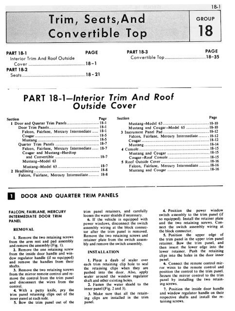
FIG. 3-<br />
.Typical Quarter <strong>Trim</strong> Water Shields<br />
R 1353.A<br />
FIG. 4- Typical Door <strong>Trim</strong> Panel <strong>and</strong> Water Shield Installation<br />
Cougar
1352-A<br />
FIG. 5. Typical Door <strong>Trim</strong> Panel <strong>and</strong> Water Shield. Mustang<br />
FIG. 6 Quarter <strong>Trim</strong> Panel Falcon, Fairlone, Mercury Intermediate
PART <strong>18</strong>-1-lnterior <strong>Trim</strong> And Roof Outside Cover <strong>18</strong>-5<br />
8. Position the arm rest <strong>and</strong> pad<br />
assembly to the panel <strong>and</strong> install the<br />
two retaining screws.<br />
COUGAR DOOR TRIM PANEL<br />
REMOVAL<br />
1. Remove the retaining screws<br />
from the window regulator h<strong>and</strong>le<br />
<strong>and</strong> the inside door h<strong>and</strong>le <strong>and</strong> remove<br />
the h<strong>and</strong>les from their shafts<br />
(Fig. 4).<br />
2. Remove the two retaining screws<br />
from the arm rest assembly <strong>and</strong> remove<br />
the assembly.<br />
3. Pry the two door pull h<strong>and</strong>le<br />
cover assemblies from the h<strong>and</strong>le <strong>and</strong><br />
remove the two retaining screws from<br />
the h<strong>and</strong>le <strong>and</strong> remove the pull h<strong>and</strong>le.<br />
4. With a putty knife, pry the<br />
trim panel retaining clips out of the<br />
inner panel <strong>and</strong> remove the panel<br />
from the door. Carefully remove the<br />
water shield, if necessary.<br />
INSTALLATION<br />
1. Place a daub of sealer over<br />
each trim retaining clip hole to seal<br />
the retaining clips when they are<br />
pushed into the door. Also, apply<br />
sealer around the window regulator<br />
shaft hole <strong>and</strong> other existing holes.<br />
2. Fasten the water shield to the<br />
inner panel (Fig. 4).<br />
3. Position the trim panel to the<br />
inner door panel <strong>and</strong> water shield<br />
<strong>and</strong> push the retaining clips into their<br />
holes.<br />
4. Position the arm rest assembly<br />
<strong>and</strong> install the two retaining screws.<br />
5. Position the inside door h<strong>and</strong>le<br />
<strong>and</strong> window regulator on their respective<br />
shafts <strong>and</strong> install the retaining<br />
screws.<br />
MUST ANG DOOR<br />
TRIM PANEL<br />
REMOVAL<br />
1. Remove the retaining screws<br />
from the window regulator h<strong>and</strong>le <strong>and</strong><br />
the inside door h<strong>and</strong>le <strong>and</strong> remove the<br />
h<strong>and</strong>les from their shafts (Fig. 5).<br />
2. Remove the two retaining screws<br />
from the arm rest assembly <strong>and</strong> remove<br />
the assembly.<br />
j. With a putty knife, pry the<br />
trim panel retaining clips out of<br />
the inner panel <strong>and</strong> remove the panel<br />
FIG. 7-Quarter <strong>Trim</strong> Panel <strong>and</strong> Water Shield-MustanQ
<strong>18</strong>-6<br />
GROUP l8-<strong>Trim</strong>, <strong>Seats</strong>, And <strong>Convertible</strong> <strong>Top</strong><br />
SECTIONAL<br />
VIEW-BB<br />
FIG. 8- Typical Quarter <strong>Trim</strong> Panel <strong>and</strong> Water Shield.<br />
Cougar<br />
R 1355-A
~<br />
from the door. Carefully remove the<br />
water shield, if necessary.<br />
INST ALLATION<br />
1. Place a daub of sealer over<br />
each trim retaining clip hole to seal<br />
the retaining clips when they are<br />
pushed into the door. Also, apply<br />
sealer around the window regulator<br />
shaft hole <strong>and</strong> other existing holes.<br />
2. Fasten the water shield to the<br />
inner panel (Fig. 5).<br />
3. Be sure that the retaining<br />
clips are installed in the trim panel.<br />
4. Position the trim panel to the<br />
inner door panel <strong>and</strong> water shield <strong>and</strong><br />
push the retaining clips into their<br />
holes.<br />
5. Position the arm rest assembly<br />
to the trim panel <strong>and</strong> install<br />
the two retaining screws.<br />
6. Place the window regulator<br />
h<strong>and</strong>le <strong>and</strong> inside door h<strong>and</strong>le on their<br />
respective shafts <strong>and</strong> install a retaining<br />
screw in each h<strong>and</strong>le.<br />
QUARTER TRIM PANEL-<br />
FALCON, FAIRLANE, MERCURY<br />
INTERMEDIATE<br />
Basically, all quarter trim panels<br />
are retained in the same manner. In<br />
view of this, one removal <strong>and</strong> installation<br />
procedure will cover all models.<br />
1. Remove the window regulator<br />
h<strong>and</strong>le <strong>and</strong> the arm rest retaining<br />
screws <strong>and</strong> remove the h<strong>and</strong>les from<br />
their shafts.<br />
2. Remove any screws retaining<br />
the trim panel to the inner panel,<br />
such as the arm rest retaining screws<br />
(Fig. 6).<br />
3. With a putty knife, pry the<br />
trim panel retaining clips out of the<br />
inner panel at each side.<br />
4. Bow the trim panel out of the<br />
retainers, <strong>and</strong> carefully loosen the<br />
wa ter shield, if necessary.<br />
5. Place a daub of sealer over<br />
each trim retaining clip hole to seal<br />
the retaining clips when they are<br />
pushed into the door. Also, apply this<br />
sealer around the window regulator<br />
shaft <strong>and</strong> other existing holes.<br />
6. Fasten the water shield to the<br />
inner panel.<br />
7. Make sure that all the retaining<br />
clips are installed in the trim<br />
panel. Place the upper edge of the<br />
trim panel in the retainer, bow the<br />
trim panel, <strong>and</strong> then insert the lower<br />
edge into the retainer. Push the retaining<br />
clips into the holes in the door<br />
inner panel (Fig. 6).<br />
8. Install the arm rest retaining<br />
screws.<br />
9. Place the friction plate against<br />
the trim panel <strong>and</strong> push the h<strong>and</strong>le<br />
onto the shaft. Install<br />
taining screws.<br />
the h<strong>and</strong>le reo<br />
COUGAR AND MUSTANG<br />
HARDTOP AND CONVERTIBLE<br />
QUARTER TRIM PANEL<br />
REMOVAl.<br />
1. Remove the rear seat cushion<br />
<strong>and</strong> the rear seat back (Refer to<br />
Part 2, Section I).<br />
2. Remove the retaining screw<br />
from the upper front trim panel cap<br />
<strong>and</strong> remove the cap, if so equipped.<br />
3. Pull the wind lace assembly<br />
from the door edge of the quarter trim<br />
panel.<br />
4. Remove the retaining screw from<br />
the quarter window regulator h<strong>and</strong>le<br />
<strong>and</strong> remove the h<strong>and</strong>le from the shaft.<br />
5. Remove the retaining screws<br />
from the trim panel <strong>and</strong> remove the<br />
panel from the inner quarter panel.<br />
6. Carefully remove the water<br />
shield, if necessary.<br />
INSTALLATION<br />
1. Place a daub of sealer over<br />
each of the retaining screw holes to<br />
seal the screw when it is installed. Also,<br />
apply sealer around the window<br />
regulator shaft hole.<br />
2. Fasten the water shield to the<br />
inner quarter panel (Fig. 7 <strong>and</strong> 8).<br />
3. Position the trim panel to the<br />
inner panel <strong>and</strong> install the retaining<br />
screws.<br />
:~<br />
UPPER FR~T<br />
Q.JARTER TRIM'<br />
PANEL.6331002<br />
."./:"<br />
i<br />
I Iii:;<br />
- ! lfi"<br />
AA~16;:;'<br />
/1;'<br />
~-::::::#'~'<br />
~.<br />
~~<br />
FIG. la-Interior<br />
Model 63<br />
UPPER FR~T QUARTER<br />
TRIM MOULDING.633 1282<br />
:/~"~i':'~'1<br />
;::~£~i:;\~<br />
4. Position the window regulator<br />
h<strong>and</strong>le on the shaft <strong>and</strong> install the<br />
retaining screw.<br />
5. Press the windlace assembly<br />
into position along the door edge of<br />
the trim panel.<br />
6. Position <strong>and</strong> install the upper<br />
trim panel cap <strong>and</strong> retaining screw,<br />
if so equipped.<br />
7. Install the rear seat back<br />
<strong>and</strong> rear seat cushion.<br />
QUARTER TRIM PANELS-<br />
MODEL 63-MUSTANG<br />
REMOVAL<br />
1. Remove the rear seat cushion.<br />
2. Tilt the rear seat back forward<br />
<strong>and</strong> remove the retaining screws<br />
from the rear floor section <strong>and</strong> remove<br />
the floor section (Fig. 9).<br />
3. Remove the two retaining bolts<br />
from the rear seat back hinges <strong>and</strong><br />
remove the seat back assembly.<br />
4; Remove the four retaining<br />
screws from the upper front quarter<br />
trim moulding <strong>and</strong> remove the moulding<br />
(Fig. 10).<br />
5. Remove the seven retaining<br />
screws from the upper front quarter<br />
trim panel <strong>and</strong> remove the panel.<br />
6. Remove the four screws retaining<br />
the rear seat latch assembly at<br />
the lower quarter panel <strong>and</strong> remove<br />
the latch assembly.<br />
7. Remove the four bolts <strong>and</strong> two<br />
screws from the lower front quarter<br />
trim panel.<br />
~~~ "-, /<br />
~§~~~~~~'i;j<br />
;,:H<br />
REAR QUARTER UPPER<br />
TR!M PANEL.6331 112<br />
~{"i,," ::==7-::~ .<br />
ki,;~~;l.;:;i)l~~t<br />
- -<br />
- LOWERR£AR<br />
--<br />
QUARTER<br />
PANEL<br />
6331222<br />
,- --<br />
LOWER FRONT BACK<br />
WINDOW TRIM PANEI-<br />
63424A68<br />
~==--<br />
~ ---<br />
TRIM<br />
--
<strong>18</strong>-8<br />
GROUP l8-<strong>Trim</strong>, <strong>Seats</strong>, And <strong>Convertible</strong> <strong>Top</strong><br />
8. Remove the carpet trim from<br />
the trim panel <strong>and</strong> disconnect the plug<br />
connectors to the courtesy light in the<br />
trim panel <strong>and</strong> remove the panel <strong>and</strong><br />
remove the li~ht from the panel.<br />
INST ALLA TIO N<br />
1. Install the courtesy light in<br />
the lower front quarter trim panel<br />
<strong>and</strong> connect the plug connectors.<br />
2. Position the trim panel to the<br />
lower quarter panel <strong>and</strong> install the<br />
retaining bolts <strong>and</strong> screws. Install<br />
the carpet trim on the trim panel.<br />
3. Position the upper front quarter<br />
trim panel <strong>and</strong> install the retaining<br />
screws.<br />
4. Position the rear seat latch<br />
assembly <strong>and</strong> install the four retainin~<br />
screws.<br />
5. Install the upper front quarter<br />
trim moulding <strong>and</strong> retaining screws.<br />
6. Position the rear seat back<br />
assembly <strong>and</strong> hinges <strong>and</strong> install the<br />
two retaining bolts in each of the<br />
hinges.<br />
7. Position the rear floor section<br />
<strong>and</strong> install the retaining screws.<br />
8. Tilt the rear seat back assembly<br />
rearward <strong>and</strong> install the rear<br />
seat back <strong>and</strong> seat cushion.<br />
HEADLINING<br />
FALCON-FAIRLANE-<br />
MERCURY INTERMEDIATE<br />
REMOVAL<br />
1. Remove the sun visors <strong>and</strong> rear<br />
view mirror.<br />
2. Remove the windshield side<br />
<strong>and</strong> upper garnish mouldings.<br />
3. Pull the door opening weatherstrips<br />
down far enough to provide access<br />
to the headlining perimeter.<br />
4. Remove the rear seat cushion<br />
<strong>and</strong> seat back.<br />
5. Remove the quarter trim<br />
panels.<br />
6. Remove the rear package tray<br />
trim panel.<br />
TRIM MOULDING-<br />
7. Remove the coat hooks <strong>and</strong> the<br />
dome light lens assemblies.<br />
8. Unhook the headlinging from<br />
the rear quarter retaining strips.<br />
9. Cut the headlining loose around<br />
the back window.<br />
10. Peel the headling from<br />
around the windshield <strong>and</strong> door openings<br />
(Figs. II, 12 <strong>and</strong> 13).<br />
11. Unhook the headlining support<br />
rods <strong>and</strong> remove the headlining<br />
assembly from the car.<br />
INSTALLATION<br />
1. Unpack <strong>and</strong> layout the new<br />
headlining.<br />
~If<br />
:"*. ~<br />
:<br />
:::;:..- :~<br />
.~...,:;,..<br />
'~rr;';,:i.<br />
III ""'o'~";"'" '.!~<br />
..~ :~'iil'r~~:.;~~<br />
REAR SUPPORT-52<strong>18</strong>0-<br />
2. Transfer the support rods from<br />
the old headlining to the new one.<br />
3. Position the headlining in the<br />
car <strong>and</strong> insert the support rod ends<br />
into their respective retaining holes<br />
in the roof side rails.<br />
4. Measure <strong>and</strong> trim excess material<br />
from the headlining around the<br />
back window.<br />
5. Apply trim cement around the<br />
back window flange <strong>and</strong> around the<br />
mating headlining edge. Tuck the<br />
headlining under the back window<br />
weatherstrip <strong>and</strong> pullout any wrinkles.<br />
6. Apply trim cement around the<br />
rear quarter area <strong>and</strong> to the mating<br />
surface of the headlining. Hook the<br />
LOWER SIDE RETAIN ER<br />
NO.3 SUPPORT (MODEL 54)-52194-5<br />
;::::(BLACK. YELLOW, MODEL 62, 52104)<br />
(GREEN. YELLOW, MODEL 54, 52103) ~'\"-: ;;~i,;,~;\,.,<br />
~--c ~'\\\ ;..'<br />
'II' 'I ~~"<br />
.,J (BRONZE- ~~LC;~,P:g;;L 62, 52105) :':/( "'~<br />
~,;<br />
SOUND ABSORBER<br />
54310<br />
=-<br />
~-~~:..,~",<br />
NO.1 SUPPORT<br />
(PURPLE. YELLOW)-52101<br />
";~}";~~~~~ (GREEN. YELLOW, NO. =- -~, MODEL 62,52103)<br />
E LLOW MO DEL 5 4 5210 5)<br />
(PINK- Y<br />
~ ~ift;!:,;'~~j~i;;<br />
, , """""" Yf<br />
A"'I'1<br />
' .,.."""... ' =-- ~<br />
HEADLINING ASSEMBLY-<br />
51916 '. ,<br />
,1)'/ ,'".:<br />
:AINER STRIP-<br />
50966<br />
~~--<br />
1~'-~- " ", .<br />
\ ~<br />
~<br />
f j - -<br />
~ :..:~<br />
SIDE REAR LOWER TACKING<br />
STRIP-50992<br />
>~:V14 C-<br />
FILLER-513A40 (GRAY-YELLOW, NO.4 SUPPORT MODEL 62, 52104) .~<br />
~ (BLACK.YELLOW, MODEL 54, 52104)<br />
~<br />
~::==::::::--<br />
\\1 (BRONZE. BRONZE, MODEL 5~, 52102)<br />
} ABSORBER-54330 ~ "' .<br />
~A~<br />
~<br />
~<br />
Rl167-B<br />
~<br />
FIG. 1<br />
Headlining Installation-Typical<br />
Mercury Intermediate, Falcon, Fairlane
REAR SOUND<br />
ABSORBER -54330<br />
SECTIONAL<br />
VIE<br />
HEADLINING ASSEMBLY<br />
, Hi . ..'<br />
C'c-<br />
--;<br />
/Il.""""".",,= 1171/ DD_~-- ~ - -. (f<br />
z."""""",~<br />
~<br />
VIEW - DD<br />
\\<br />
."<br />
CENTER SOUND<br />
ABSORBER - S4322<br />
\<br />
REAR SaUNa<br />
B -"<br />
ABSORBER - 54330<br />
C<br />
:~<br />
FRONT SOUND<br />
ABSORBER-S4310<br />
f';;:;=:<br />
N AA D<br />
. ~<br />
~ NO.3SUPPORT<br />
(BLUE. BLUE) 52103<br />
REAR SUPPO~T<br />
RETAINER-S2<strong>18</strong>0<br />
1/' IJ<br />
NO.8 SUPPORT<br />
(BLUE. GRAY) 52108<br />
SECTION~' =-=<br />
VIEW - BB ;;;o...c.<br />
NO.'5~SUPPORT<br />
. (BLUE - PURPLE) 52105<br />
NO.6 SUPPORT r<br />
, (BLUE-GREEN) 52106.~<br />
NO.7 SUPPORT ': .~<br />
(BLUE. PINK)<br />
E<br />
~<br />
N<br />
;~<br />
VIEW-EE<br />
NO.1 SUPPORT<br />
(YELLOW. PURPLE) 52101<br />
, NO.2 SUPPORT<br />
'(BRONZE, BRONZE) 52102<br />
-<br />
52107 ~~/r<br />
l ... TRIM MOULOING-<br />
SECTIONAL 03542<br />
VIEW - AA<br />
HEAD.LINING RETAINER<br />
STRIP-50966<br />
NO.4 SUPPORT<br />
:(BLUE. BROWN) 52104<br />
B-C.D.E.F<br />
ADHESIVE (C2AZ.19C52S.A:<br />
125- B<br />
FIG. 72.<br />
Headlining Installation<br />
.Typical Station Wagon<br />
FIG. 13-<br />
Headlining Installation. .Fairlane,<br />
Mercu ry Intermediate<br />
.Model 63
<strong>18</strong>-10<br />
GROUP la-<strong>Trim</strong>, <strong>Seats</strong>, And <strong>Convertible</strong> <strong>Top</strong><br />
headlining material over the retaining<br />
strips <strong>and</strong> bend the retainer tabs<br />
down.<br />
7. Apply trim cement to the roof<br />
header <strong>and</strong> to the mating surface<br />
around the front of the headlining.<br />
8. Position the headlining to the<br />
roof header <strong>and</strong> pullout any wrinkles.<br />
9. Apply trim cement around the<br />
door openings <strong>and</strong> mating surface of<br />
the headlining. Steam between the<br />
headlining panels as required to help<br />
remove any wrinkles <strong>and</strong> secure the<br />
headlining perimeter.<br />
10. <strong>Trim</strong> the excess headlining<br />
material.<br />
11. Install the package tray <strong>and</strong><br />
quarter trim panels.<br />
12. Install the coat hooks <strong>and</strong><br />
dome light lens.<br />
13. Install the windshield upper<br />
<strong>and</strong> side interior mouldings.<br />
14. Install the windlace around<br />
the door openings.<br />
15. Install the rear view mirror<br />
<strong>and</strong> sun visors.<br />
16. Install the rear seat back <strong>and</strong><br />
rear seat cushion.<br />
17. Clean the interior <strong>and</strong> headlining.<br />
MUSTANG (MODEL 63)<br />
1. Remove the sun visors <strong>and</strong> the<br />
inside rear view mirror.<br />
2. Remove the roof headlining<br />
side front retainer from each A pillar<br />
(Fig. l4-View BB).<br />
3. Remove 5 screws <strong>and</strong> remove<br />
the back window upper garnish<br />
moulding.<br />
4. Remove 4 screws <strong>and</strong> remove<br />
the quarter trim upper front mouldings<br />
<strong>and</strong> caps (Fig. 10).<br />
5. Remove 5 screws <strong>and</strong> remove<br />
the quarter trim upper front panel.<br />
6. Remove the windlace from the<br />
door openings (Fig. 14).<br />
7. Cut the headlining at the windshield<br />
weatherstrip <strong>and</strong> loosen the<br />
headlining.<br />
8. Cut the headlining at the back<br />
window weatherstrip <strong>and</strong> loosen the<br />
headlining.<br />
9. Pull the headlining from the<br />
door opening pinch weld, disconnect<br />
the bows, <strong>and</strong> remove the headlining.<br />
10. Place the old <strong>and</strong> new headlinings<br />
on a clean surface <strong>and</strong> transfer<br />
the bows to the new headlining.<br />
The bows are color coded on one<br />
end for identification (Fig. 14).<br />
11. Position the headlining in the<br />
car <strong>and</strong> install the roof bows in the<br />
side rails.<br />
12. Apply trim cement (C2AZ-<br />
19C525-A) to the back side of the<br />
headlining at the back window opening.<br />
13. Tuck the headling under the<br />
back window weatherstrip. Smooth<br />
out any wrinkles or gathering <strong>and</strong><br />
trim off any excess material.<br />
14. Apply trim cement (C2AZ-<br />
19C525-A) to the back side of the<br />
headlining at the windshield opening.<br />
15. Tuck the headlining under the<br />
windshield weatherstrip. Smooth out<br />
any wrinkles or gathering <strong>and</strong> trim<br />
off any excess material.<br />
16. Apply trim cement (C2AZ-<br />
19C525-A) to the roof side rails at<br />
the door openings. Position the headlining<br />
to the side rails <strong>and</strong> trim off<br />
any excess material (Fig. 14).<br />
17. Install the windlace in the<br />
door openings.<br />
<strong>18</strong>. Install the roof headlining side<br />
front retainer at each A pillar.<br />
19. Install the inside rear view<br />
mirror <strong>and</strong> sun visors.<br />
20. Install the right <strong>and</strong> left quarter<br />
trim upper front panels (Fig. 10).<br />
21. Install the quarter trim upper<br />
front mouldings <strong>and</strong> front caps.<br />
22. Install the back window upper<br />
garnish moulding.<br />
23. Clean all mouldings <strong>and</strong> remove<br />
any headlining scraps from the<br />
car.<br />
MUSTANG AND COUGAR<br />
(MODEL 65)<br />
The procedure for the Cougar <strong>and</strong><br />
Mustang is the same except for lights<br />
FIG. 14-Headlining Installation-Mustang Model 63
PART <strong>18</strong>-1-lnterior <strong>Trim</strong> And Roof Outside Cover<br />
<strong>18</strong>-<br />
in the roof quarters on the Cougar<br />
models.<br />
1. Remove the rear seat cushion<br />
<strong>and</strong> seat back <strong>and</strong> remove the quarter<br />
trim panels.<br />
2. Remove 2 clips <strong>and</strong> retainers<br />
<strong>and</strong> remove the package tray.<br />
3. Bend back the headlining lower<br />
rear side retaining strip tabs<br />
(Fig. 15).<br />
4. Remove the coat hanger hooks.<br />
5. Remove the sun visors.<br />
6. Remove the headlining retainer<br />
from each A pillar (Fig. 15).<br />
7. Remove 3 screws <strong>and</strong> remove<br />
the rear view mirror.<br />
8. Remove the door opening windlace<br />
from each side of the body.<br />
9. Cut the headlining along the<br />
edge of the windshield <strong>and</strong> back<br />
window weatherstrips.<br />
10. Remove the headlining from<br />
the right <strong>and</strong> left sides in the package<br />
tray area. Then, remove the headlining<br />
from the roof side rails <strong>and</strong><br />
remove it from the car.<br />
11. Place the new <strong>and</strong> old head-<br />
lining on a clean surface <strong>and</strong> transfer<br />
the headlining: upport wires in<br />
sequence to the new headlining. The<br />
roof bows are color coded on one<br />
end. When ordering new roof bows,<br />
be sure to note the color code.<br />
12. Position the headlining in the<br />
car <strong>and</strong> install the rear support wire<br />
<strong>and</strong> 2 rear support retainers. Then,<br />
install the remaining support wires,<br />
working towards the front of the car.<br />
13. <strong>Trim</strong> the headlining at the<br />
windshield header, leaving approximately<br />
1/2 inch of material for tucking<br />
under the windshield header<br />
weatherstrip.<br />
14. Apply trim cement to the<br />
windshield header <strong>and</strong>, starting from<br />
the center, cement the he&dlining to<br />
the header. Insert the remainip'J headlining<br />
material under the windshield<br />
header weatherstrip.<br />
15. <strong>Trim</strong> the headlining at the<br />
rear window, leaving approximately I /2<br />
inch of material for tucking under the<br />
weatherstrip. Apply trim cement to the<br />
rear window upper rail <strong>and</strong>, starting<br />
from the center, cementhe headlining<br />
to the upper rail. Insert the remaining<br />
material under the rear window<br />
weatherstrip.<br />
16. Pull the headlining down at<br />
the sides to remove wrinkles. Cut the<br />
listings at each end to eliminate gathering<br />
of the material.<br />
17. Apply trim cement to the left<br />
roof side rail over the door <strong>and</strong> quarter<br />
window. Pull the headlining down<br />
to remove wrinkles <strong>and</strong> cement it in<br />
place. Then, trim the headlining as<br />
necessary. Cement <strong>and</strong> trim the right<br />
side the same way.<br />
<strong>18</strong>. Straighten the metal prongs<br />
(V iew A A Fig. 15) at the package<br />
tray area; attach the headlining to<br />
the prongs <strong>and</strong> bend the prongs down<br />
as shown.<br />
19. Roll the lower rear side retaining<br />
strips into the headlining <strong>and</strong><br />
retain them by bending the tabs<br />
(V iew AA).<br />
20. Install the right <strong>and</strong> left roof<br />
side windlace at the door <strong>and</strong> windowopenings.
F () - :~ ;:<br />
<strong>18</strong>-12<br />
GROUP l8-<strong>Trim</strong>, <strong>Seats</strong>, And <strong>Convertible</strong> <strong>Top</strong><br />
21. Install the headlining retainer<br />
at the A pillar (View 00).<br />
22. Install the rear view mirror,<br />
sun visors, <strong>and</strong> coat hooks.<br />
23. Slide the package tray into position<br />
<strong>and</strong> install the retainers <strong>and</strong><br />
clips. Then, install the quarter trim<br />
panels <strong>and</strong> rear seat back <strong>and</strong> cushion.<br />
INSTRUMENT PANEL PAD<br />
FALCON, FAIRLANE, MERCURY<br />
INTERMEDIATE<br />
REMOVAL<br />
1. Open the glove box door. Remove<br />
the glove box liner retaining<br />
screws <strong>and</strong> remove the glove box<br />
liner.<br />
2. Fairlane: Remove the radio<br />
control knobs <strong>and</strong> the control shaft<br />
retaining nuts.<br />
3. Remove the instrument cluster<br />
retaining screws.<br />
4. Pull the instrument cluster out<br />
far enough to disconnect the speedometer<br />
cable, light sockets <strong>and</strong> wiring<br />
connectors from the instrument<br />
cluster. Remove the instrument<br />
cluster.<br />
5. Remove the nuts retaining the<br />
safety cover to the instrument panel.<br />
6. Pry up <strong>and</strong> remove the safety<br />
cover.<br />
INSTALLATION<br />
1. Position the new safety cover<br />
to the instrument panel (Figs. 16 <strong>and</strong><br />
17).<br />
2. Install the safety cover retaining<br />
nuts.<br />
3. Position the instrument cluster<br />
to the instrument panel. Connect<br />
the wiring connectors <strong>and</strong> the speedometer<br />
cable. Install the light sockets.<br />
4. Install the instrument cluster<br />
retaining screws.<br />
5. Fairlane: Install the radio<br />
control shaft retaining nuts <strong>and</strong> the<br />
radio control knobs.<br />
6. Position the glove box liner<br />
in place <strong>and</strong> install the glove box<br />
liner retaining screws.<br />
COUGAR INSTRUMENT<br />
PANEL PAD<br />
REMOVAL<br />
I. Disconnect the battery ground<br />
cable.<br />
2. Remove the thirteen (13) retaining<br />
screws from the front of the<br />
instrument panel pad assembly (Fig.<br />
<strong>18</strong>).<br />
3. Remove the four retaining screws<br />
from the heater control assembly <strong>and</strong><br />
position the control out of the instrument<br />
panel. Thru the heater control<br />
opening, disconnect the ~peedometer<br />
cable.<br />
4. Remove the three retaining<br />
screws from the ash receptacle <strong>and</strong><br />
disconnect the connector to the cigar<br />
lighter. Remove the receptacle assembly<br />
from the instrument panel.<br />
5. Thru the receptacle opening,<br />
remove the nut <strong>and</strong> washer retaining<br />
the inboard edge of the instrument<br />
cluster to the instrument panel.<br />
6. Remove the seven retaining<br />
screws from the instrument cluster.<br />
Position the cluster out of the panel<br />
<strong>and</strong> disconnect the windshield wiper<br />
switch, the multiple connector <strong>and</strong><br />
the push on connector to the constant<br />
voltage regulator <strong>and</strong> then remove<br />
the cluster.<br />
~<br />
PAD<br />
I ! :Y-- h<br />
~ '<br />
~:7<<br />
~", <br />
A '~~---<br />
~~;~::Z::"""'Q<br />
-:~ ~~~:<br />
. ~<br />
(I' 11" ::::::--~ .<br />
J' , ; I . '\: \<br />
i ..<br />
",+~..<br />
i i! I,<br />
. 0 "<br />
,::.;-1'<br />
1<br />
AND RETAINER<br />
ASSEMBL Y -04282<br />
" ""<br />
,<br />
';104<br />
;; :::::::::::::::::;::::::::::::::"<br />
_.-:::::::~<br />
"-~ :;<br />
]<br />
FALCON<br />
~,<br />
~ _r ' ~..:.~<br />
;;::;"'~~:::~,,::,,~ lit ~:~<br />
0 ..~.k---/~<br />
<br />
~ ,C:::~~\<br />
'<br />
, -~""'~:::=~<br />
-::::;.-<br />
._~-<br />
./-<br />
-~~/ '<br />
~:~;jJ) r' -<br />
~<br />
./~~Zij"~ ;~9- :::.' .~- -::::::---11<br />
.;.-<br />
);;;;'1<br />
FIG. 16<br />
FAIRLANE<br />
i ' :<br />
'V::;::;;:;::<br />
-~<br />
R 1261-D<br />
Instru ment Pane! Pad Installation .Falcon, Fairlane<br />
~~
~<br />
:.;;.;.; ~c,:::~<br />
"--:-<br />
r;:;:~<br />
-:--.:.~<br />
-~~"i-;~'<br />
,oP<br />
'g';;;;oo.<br />
PAD AND RETAINER<br />
04282<br />
~<br />
~<br />
"--- ~<br />
-='='1~<br />
.. ,i<br />
:;;;: 'O~~' - ..-~::::::::::::::~;;';/; ~_.,;<br />
,~<br />
_..~~<br />
(J -<br />
-<br />
;<br />
~;,;~<br />
-.-:::::: .. '<br />
:.::;;::::::... ...<br />
III'<br />
/,~~<br />
.r_~' ~ ~ -' 0<br />
::.~ ,-<br />
~ .-::::::::;.<br />
:::;"::'-"';::<br />
~- ~.-:::;<br />
& -"<br />
;;~<br />
. I<br />
FIG. 17-lnstrument Panel Pod Installation<br />
~~<br />
Mercury Intermediate<br />
~VIEW. A<br />
~-<br />
~<br />
jM~~~t!;r;;iilt[<br />
r,:;i;;:::,..~<br />
::;:;;;::;: VIEW - B<br />
c<br />
R 1158.D
<strong>18</strong>-14<br />
GROUP <strong>18</strong>-<strong>Trim</strong>, <strong>Seats</strong>, And <strong>Convertible</strong> <strong>Top</strong><br />
7. Remove the retaining screws<br />
from the glove box assembly <strong>and</strong> remove<br />
the assembly.<br />
8. Working thru the glove box<br />
opening, remove the retaining nut from<br />
the lower right end of the instrument<br />
pad.<br />
9. Remove the five screws <strong>and</strong> four<br />
nuts retaining the upper finish panel<br />
<strong>and</strong> remove the panel.<br />
10. Remove the retaining screws<br />
from the top instrument pad retainer<br />
mouldings <strong>and</strong> remove the mouldings.<br />
II. Working thru the heater control<br />
opening remove the retaining nut<br />
from the lower left end of the pad<br />
assembly.<br />
12. Pry the A pillar pad assemblies<br />
loose <strong>and</strong> remove them.<br />
13. Remove the six nuts retaining<br />
the pad assembly to the instrument<br />
panel <strong>and</strong> remove the pad assembly.<br />
INSTALLATION<br />
1. Position the pad assembly to<br />
the instrument panel <strong>and</strong> install the<br />
six retaining nuts.<br />
2. Install the lower right <strong>and</strong><br />
left nuts retaining the pad assembly<br />
to the instrument panel.<br />
3. Position the center finish<br />
panel <strong>and</strong> install five retaining screws<br />
<strong>and</strong> four nuts.<br />
4. Push the right <strong>and</strong> left A<br />
pillar pads into position to engage<br />
the retaining clips.<br />
S. Position the top instrument<br />
pad retainer mouldings <strong>and</strong> install<br />
the retaining screws.<br />
6. Insert the glove box in its<br />
opening <strong>and</strong> install the retaining<br />
screws.<br />
7. Connect the windshield wiper<br />
switch plug, the constant voltage regulator<br />
connector <strong>and</strong> the multiple<br />
connector to the instrument cluster.<br />
Position the cluster to the instrument<br />
panel <strong>and</strong> install the seven retaining<br />
screws.<br />
8. Thru the ash receptacle opening,<br />
install the inboard cluster retaining<br />
washer <strong>and</strong> nut.<br />
9. Connect the cigar lighter connector.<br />
Position the ash receptacle in<br />
the instrument panel <strong>and</strong> install the<br />
three retaining screws.<br />
10. Thru the heater control opening,<br />
connect the speedometer cable.<br />
11. Position the heater control<br />
assembly to the instrument panel <strong>and</strong><br />
install the retaining screws.<br />
12. Install the thirteen (13) retaining<br />
screws in the front of the instrument<br />
pJid assembly.<br />
13. Connect the ba ttery.<br />
MUST ANG INSTRUMENT<br />
PANEL PAD<br />
REMOVAL<br />
1. Disconnect the battery ground<br />
cable. Remove the three retaining<br />
screws from the ash receptacle assembly,<br />
<strong>and</strong> disconnect the COnneClJr to<br />
the cigar lighter.<br />
2. Remove the four screws retaining<br />
the heater control assembly to<br />
the instrument panel <strong>and</strong> position the<br />
assembly out of the panel<br />
3. Thru the heater control opening,<br />
remove the nut retaining the<br />
lower left end of the pad to the instrument<br />
panel (Fig. 19).<br />
4. Remove the five retaining screws<br />
from the instrument cluster. Thru<br />
the ash receptacle opening, remove<br />
the nut <strong>and</strong> washer retaining the inboard<br />
end of the cluster to the instrument<br />
panel Position the cluster out<br />
of the instrument panel.<br />
5. Remove the three retaining screws<br />
from the glove box assembly.<br />
6. Remove the retaining nut from<br />
the lower right end of the pad to the<br />
instrument panel<br />
7. Remove the retaining nuts from<br />
the lower, upper <strong>and</strong> center finish<br />
panels <strong>and</strong> remove the panels.<br />
8. Remove the seven screws retaining<br />
the top instrument pad retainer<br />
mouldings <strong>and</strong> remove the mouldings.<br />
9. Remove four pad retaining<br />
screws from the forward edge of the<br />
pad.<br />
10. Pull the instrument panel<br />
pad from the instrument panel.<br />
.;;t:<br />
INSTRUMENT<br />
PftNEL<br />
PAD<br />
04282<br />
~ '<br />
"<br />
,.-,--p-<br />
\,( ~<br />
FIG. 19<br />
-;;./ fJ<br />
#,VA<br />
A /;i\~:-/<br />
"<br />
r<br />
NSTAL ATION<br />
1. Position the pad to the instrument<br />
panel.<br />
2. Install the four pad retaining<br />
screws at the forward edge of the pad.<br />
3. Thru the heater control opening<br />
install the retaining nuts on the<br />
lower left of the instrument pad.<br />
4. Install the retaining nut on<br />
the lower right of the instrument pad.<br />
5. Position the center <strong>and</strong> upper<br />
fin ish panel <strong>and</strong> install the retaining<br />
screws.<br />
6. Position the lower right finish<br />
panel to the instrument panel <strong>and</strong><br />
install the retaining nut <strong>and</strong> screws.<br />
7. Position the cluster to the<br />
instrument panel <strong>and</strong> install the five<br />
retaining screws, also install the<br />
inboard cluster retaining nut <strong>and</strong><br />
washer.<br />
8. Connect the cigar lighter connector.<br />
Insert the ash receptacle assembly<br />
in the instrument panel <strong>and</strong><br />
install the three retaining screws.<br />
9. Position the heater control assembly<br />
to the instrument panel <strong>and</strong><br />
install the four retaining screws.<br />
10. Insert the glove box assembly<br />
<strong>and</strong> install the three retaining screws.<br />
11. Position the top instrument<br />
pad retainer mouldings <strong>and</strong> install<br />
the retainer screws.<br />
12. Connect the battery.<br />
PAD TOP<br />
MOOLDING ,<br />
045.22-3 SUPPORt<br />
'045C72 ---<br />
v<br />
"""F<br />
UPPER<br />
FINISH<br />
PANEL<br />
044A90<br />
Instrument Panel Pad Installation-Mustang<br />
I -LOWER<br />
~ FINISH<br />
PAN£L<br />
044A12<br />
R 1275-B
PART <strong>18</strong>-1-lnterior <strong>Trim</strong> And Roof Outside Cover <strong>18</strong>-15<br />
CONSOLE<br />
CONSOLE-MUST ANG AND<br />
COUGAR<br />
REMOV AI.<br />
I. Remove the set screw from the<br />
gear selector lever h<strong>and</strong>le <strong>and</strong> remove<br />
the h<strong>and</strong>le. Pry the top cover pad<br />
loose <strong>and</strong> remove the pad.<br />
2. Raise the door on the glove<br />
box <strong>and</strong> remove the two retaining<br />
screws from the shift lever opening covcr<br />
<strong>and</strong> remove the cover (Fig. 20).<br />
3. Remove the three screws <strong>and</strong> retainers<br />
from the dial assembly to the<br />
console.<br />
4. Remove the two screws retaining<br />
the radio to the rear support bracket.<br />
5. Remove the six screws retaining<br />
the radio <strong>and</strong> console assembly<br />
<strong>and</strong> remove the assembly. Disconnect<br />
thc antcnna wire <strong>and</strong> feed wires to<br />
tht: radio <strong>and</strong> the connector to the<br />
consolc lamp wiring.<br />
INSTALLATION<br />
I. Connect the connector to the<br />
console lamp wiring <strong>and</strong> connect the<br />
radio wiring.<br />
2. Position the radio <strong>and</strong> console<br />
assl:mbly <strong>and</strong> install thl: six retain-<br />
Ing screws.<br />
-,. Position the radio to its rear<br />
su pport bracket <strong>and</strong> install the retaining<br />
~crews.<br />
4. Install the dial assembly retainers<br />
<strong>and</strong> three retaining screws.<br />
5. Position the shift lever opening<br />
cover on the console <strong>and</strong> install<br />
the two retaining screws.<br />
6. Position the top cover pad <strong>and</strong><br />
snap the pad into place.<br />
7. Position the shift lever h<strong>and</strong>le<br />
on the shift lever <strong>and</strong> install the retaining<br />
screws.<br />
ROOF CONSOLE-COUGAR<br />
I. Remove two console attaching<br />
screws <strong>and</strong> pull the console down to<br />
unclip the two retainers (Fig. 21).<br />
2. Disconnect the wires from the<br />
console <strong>and</strong> remove the console from<br />
the vehicle.<br />
3. Position the console in the vehicle<br />
<strong>and</strong> connect the wires.<br />
4. Position the console to the roof<br />
<strong>and</strong> install the two retainers <strong>and</strong> attaching<br />
screws.
<strong>18</strong>-16<br />
GROUP l8-<strong>Trim</strong>,<br />
<strong>Seats</strong>, And <strong>Convertible</strong> <strong>Top</strong><br />
,<br />
FIG.2<br />
Couga r Roof Console<br />
ROOF OUTSIDE COVER<br />
~<br />
FALCON, FAIRLANE AND<br />
MERCURY INTERMEDIATE<br />
REMOVAL<br />
4. Remove the side <strong>and</strong> rear belt<br />
mouldings.<br />
5. Remove the back window outside<br />
mouldings. Remove the back<br />
window <strong>and</strong> weatherstrip.<br />
6. Remove the windshield wiper<br />
arm assemblies <strong>and</strong> remove the top<br />
cowl panel.<br />
7. Remove the side, top <strong>and</strong> bottom<br />
windshield outside mouldings.<br />
8. From within the vehicle remove<br />
the rear view mirror assembly,<br />
the windshield pillar cap mouldings<br />
<strong>and</strong> the plastic windshield header<br />
moulding.<br />
9. Cut the windshield sealer as<br />
described in Part 17-3 <strong>and</strong> remove<br />
the windshield.<br />
10. Remove the sealer from the<br />
windshield pinch weld flange <strong>and</strong><br />
remove the moulding retainer clips.<br />
11. Remove the drip rail moulding<br />
<strong>and</strong> then using a 0.128 to 0.132<br />
inch diameter drill, remove the rivets<br />
from the drip rail cover retainers<br />
<strong>and</strong> discard the retainers.<br />
12. Remove the staples from the<br />
front <strong>and</strong> back window opening that<br />
are retaining the cover <strong>and</strong> remove<br />
the cover from the roof.
PART <strong>18</strong>-1-lnterior <strong>Trim</strong> And Roof Outside Cover <strong>18</strong>-17<br />
FIG. 22. Typical Roof Outside Cover Installation Mercu ry Intermediate, Falcon, Fai rlane<br />
13. Remove the old adhesive from<br />
the roof area with a scraper or use<br />
an appropriate cleaning solvent. It<br />
is extremely important that the entire<br />
roof <strong>and</strong> drip rails are thoroughly<br />
cleaned.<br />
INSTALLATION<br />
It is recommended that drive nails<br />
be substituted for the staples shown<br />
in Fig. 22.<br />
Wherever possible, use the existing<br />
drive nail or screw holes. Therefore,<br />
each location should be identified<br />
on the pinch weld flange with<br />
a wax crayon.<br />
Seal all unused holes with either<br />
CIAZ-19627-A Pressure Sensitized<br />
Tape or AB-19560-A caulking cord.<br />
1. Carefully position the outside<br />
cover on the roof panel. (Fore <strong>and</strong><br />
Aft center punch marks have been<br />
provided in the cover for centering<br />
purposes.)<br />
2. With the cover properly positioned<br />
<strong>and</strong> temporarily secured, apply<br />
an even coating of C2AZ-19C-<br />
525-A adhesive to the roof panel <strong>and</strong><br />
a like amount to the corresponding<br />
area of the roof outside cover assembly.<br />
For best results, secure limited<br />
sections at a time. Make certain<br />
that the adhesiye is not lumpy as it<br />
will be objectionable from an appearance<br />
stdndpoint.<br />
3. Using a 0.128 to 0.132 inch<br />
diameter drill, pierce the vinyl material<br />
at the existing staple or screw<br />
hole locations. Install drive nails in<br />
each of the holes.<br />
4. Position both drip rail re.tainers<br />
<strong>and</strong>, using the same drill referred to<br />
above, pierce the vinyl at each of<br />
the holes. Install the Pop rivets from<br />
the underside of the drip rail except<br />
at the extreme rear hole in which<br />
case the rivet should be inserted from<br />
the retainer side.<br />
5. <strong>Trim</strong> the excess cover material<br />
from around the entire perimeter.<br />
6. Apply sealer C3AZ-19562-A<br />
(for white tops) or sealer C3AZ-<br />
19562-B (for black tops) over the<br />
entire surface of the drip rail retainers.<br />
With the drip rail properly<br />
sealed, a minimum depth of 1/8 inch<br />
should be retained for adequate<br />
water drainage. Place masking tape<br />
on the cover assembly for the entire<br />
length of the drip rail before applying<br />
sealer. After sealer has been applied,<br />
remove the tape.<br />
7. Install the drip rail mouldings.<br />
8. Install the back belt center <strong>and</strong><br />
side mouldings.<br />
9. Reposition <strong>and</strong> secure the headlining.<br />
10. Install the back window <strong>and</strong><br />
outside window mouldings.<br />
II. Install the quarter trim panel<br />
retainer mouldings <strong>and</strong> quarter window<br />
garnish mouldings.<br />
12. Install the package tray panel,<br />
quarter panels, rear seat back <strong>and</strong><br />
seat cushion.<br />
13. Install the windshield.<br />
14. Install the windshield interior<br />
garnish mouldings <strong>and</strong> sun visor assemblies.<br />
15. Install the windshield exterior<br />
mouldings, retainers, <strong>and</strong> windshield<br />
wiper blade assemblies.<br />
ROOF OUTSIDE COVER-<br />
MUSTANG AND COUGAR<br />
REMOVAL<br />
1. Disconnect the battery negative<br />
cable. At this time also unpack <strong>and</strong><br />
spread out the roof cover.<br />
2. Re!:l1°ve the windshield wiper<br />
arms. Also remove the windshield exterior<br />
mouldings using tool T64P-<br />
420068 orC (Refer to Part 17-3).<br />
3. Remove the rear seat cushion<br />
<strong>and</strong> rear seat back.<br />
4. Remove the five retaining screws<br />
from each of the quarter trim panels<br />
<strong>and</strong> remove the panels.
<strong>18</strong>-<strong>18</strong> GROUP l8-<strong>Trim</strong>, <strong>Seats</strong>, And <strong>Convertible</strong> <strong>Top</strong><br />
FIG. 23<br />
Outside Roof Cover Installation<br />
Mustang<br />
SECTIONAL<br />
VIEW-AA<br />
SECT I!<br />
R 1361-A<br />
~<br />
FIG. 24 Outside Roof Cover Installation Cougar
PART <strong>18</strong>-1-lnterior <strong>Trim</strong> And Roof Outside Cover <strong>18</strong>-19<br />
5. On the Mustang only, loosen<br />
the headlining at the roof quarters.<br />
6. Remove the retaining nuts from<br />
the right <strong>and</strong> left h<strong>and</strong> back side belt<br />
mouldings <strong>and</strong> remove the mouldings.<br />
Also the back belt moulding below<br />
the rear window on the Cougar<br />
(Figs. 23 <strong>and</strong> 24).<br />
7. Remove the exterior moulding<br />
from around the rear window with tool<br />
T64P-42006-B or C.<br />
8. Remove the moulding retainers<br />
from around the windshield <strong>and</strong> rear<br />
window.<br />
9. Remove the left <strong>and</strong> right roof<br />
side drip rail mouldings.<br />
10. On the Cougar only, remove<br />
the right <strong>and</strong> left weatherstrips <strong>and</strong><br />
remove the ten retaining screws from<br />
each of the weatherstrip retainers<br />
<strong>and</strong> remove the retainers. Also remove<br />
the four rivets from each of the<br />
drip rail moulding extensions <strong>and</strong> remove<br />
the extensions (Fig. 25).<br />
11. Remove the rivets retaining<br />
the right <strong>and</strong> left drip rail retainers<br />
<strong>and</strong> remove the retainers. The rivets<br />
may be drilled out with a 0.128 to<br />
0.132 diameter drill.<br />
12. Clean all mouldings <strong>and</strong> retainers<br />
<strong>and</strong> clean the excess sealer<br />
at the windshield <strong>and</strong> rear window.<br />
13. Remove the outside roof cover,<br />
leaving the staples in place. Remove<br />
the old adhesive from the roof area<br />
with a scraper or appropriate clean-<br />
ing solvent. It is extremely important<br />
that the entire roof <strong>and</strong> drip rail are<br />
thoroughly cleaned.<br />
INSTALLATION<br />
It is necessary that drive nails<br />
be substituted during installation<br />
for the staples.<br />
Seal all unused holes <strong>and</strong> staples<br />
with sealer AB-19560A.<br />
1. Locate the center line on the<br />
roof cover using the center punch<br />
marks that have been provided in the<br />
cover for this purpose. Also mark<br />
the center line of the roof to allow<br />
for proper alignment of the roof<br />
cover.<br />
2. Apply Vinyl Roof Adhesive<br />
C5AZ-19C525-A to one half of the<br />
roof <strong>and</strong> the corresponding half of the<br />
roof cover, from the center line to the<br />
seam. Make certain that the adhesive<br />
is not lumpy as it will be objectionable<br />
from an appearance<br />
st<strong>and</strong>point.<br />
3. Carefully align the center<br />
lines of the roof cover <strong>and</strong> roof.<br />
Then stretch <strong>and</strong> smooth the roof cover<br />
into position.<br />
4. Apply adhesive to the remaining<br />
part of the roof <strong>and</strong> the corresponding<br />
roof cover <strong>and</strong> install the<br />
cover as outlined in the preceeding<br />
step.<br />
5. Apply adhesive to the remain-<br />
ing parts of the roof <strong>and</strong> roof cover,<br />
except the window opening.<br />
6. Position the remaining parts<br />
of the roof cover to the roof sides<br />
<strong>and</strong> roof quarters, stretch <strong>and</strong> smooth<br />
as necessary. <strong>Trim</strong> or make any<br />
angular cuts in the roof cover around<br />
the window openings. On the .cougar<br />
only; start below the rear window.<br />
7. <strong>Trim</strong> all selvage from the cover,<br />
leaving about 1/2 inch around the<br />
window openings.<br />
8. Apply adhesive to the front<br />
pillars <strong>and</strong> position the cover.<br />
9. Apply adhesive to the window<br />
opening areas <strong>and</strong> stretch the cover<br />
into position. Cut the cover from<br />
around the moulding retainer studs.<br />
10. Using an awl, pierce the roof<br />
cover at intervals of 1 1/2 inches<br />
around the window openings. Install<br />
the drive nails in each of the holes<br />
in the roof cover. Be sure to apply<br />
sealer to each of the nails before<br />
they are installed. Also take precautions<br />
to protect the window glass<br />
during this operation.<br />
II. Position both drip rail retainers<br />
<strong>and</strong>, with the awl pierce the<br />
roof cover at each of the holes. Insta<br />
II the seventeen (17) retain ing<br />
rivets in the retainers. On the Cougar<br />
it is also necessary to install four<br />
rivets in the drip moulding extensions.<br />
12. Install the right <strong>and</strong> left<br />
h<strong>and</strong> drip rail mouldings.<br />
VIEW-A<br />
.~~<br />
ADHESIVE<br />
~ A<br />
J VIEW-B VIEW-C R 1372.A<br />
/<br />
/'<br />
/<br />
0<br />
FIG. 25<br />
Roof Side Rail Weatherstrip Installation-Cougar
<strong>18</strong>~20 GROUP l8-<strong>Trim</strong>, <strong>Seats</strong>, And <strong>Convertible</strong> <strong>Top</strong><br />
13. On the Cougar only; install<br />
the weatherstrips <strong>and</strong> the weatherstrip<br />
retainers shown in Fig. 25.<br />
14. Install the exterior window<br />
moulding retainers around the windshield<br />
<strong>and</strong> rear window. Also apply<br />
sealer AB-19560A around the windshield<br />
<strong>and</strong> rear window.<br />
15. Position <strong>and</strong> install the wind-<br />
shield <strong>and</strong> rear window exterior<br />
mouldings.<br />
16. On the Cougar only; install<br />
the back belt mouldings <strong>and</strong> nine retaining<br />
nuts below the rear window.<br />
17. Install the back side belt<br />
mouldings <strong>and</strong> the retaining nuts.<br />
<strong>18</strong>. On the Mustang only; install<br />
the headlining at the roof quarters.<br />
19. Position <strong>and</strong> install the quarter<br />
trim panels <strong>and</strong> install the rear<br />
seat back <strong>and</strong> seat cushion.<br />
20. Install the windshield wipers<br />
<strong>and</strong> thoroughly clean the cover <strong>and</strong><br />
moulding areas.<br />
21. Connect the battery negative<br />
cable.
1 St<strong>and</strong>ard Seat Removal <strong>and</strong> <strong>Seats</strong><br />
<strong>and</strong> Seat Installation Track<br />
Rear Front Seat Seat Seat Back Cushion Cushion Back Cover Cover<br />
Cover Cover<br />
Removal <strong>and</strong> Installation<br />
<strong>18</strong>-21<br />
Section<br />
Front Seat Cushion <strong>and</strong>/or Back<br />
Rear Seat Cushion <strong>and</strong>/or Back.<br />
2 Bucket <strong>Seats</strong>-Manual ,<br />
Page<br />
<strong>18</strong>-21<br />
<strong>18</strong>-21<br />
<strong>18</strong>-21<br />
,<strong>18</strong>-22<br />
,<strong>18</strong>-22<br />
<strong>18</strong>-22<br />
,<strong>18</strong>-22<br />
,<strong>18</strong>-23<br />
<strong>18</strong>-22<br />
.<strong>18</strong>-26<br />
.<strong>18</strong>-26<br />
Section<br />
Seat Front <strong>and</strong> Seat Cushion Track Cover<br />
3 Power Front Removal <strong>Seats</strong> Seat <strong>and</strong> Back Installation.<br />
Cover<br />
Bucket Bench Seat Seat Track Motor Track<br />
4 Seat Belts <strong>and</strong> Shoulder Straps<br />
Removal <strong>and</strong> Installation ,<br />
Page<br />
<strong>18</strong>-26<br />
<strong>18</strong>-26<br />
<strong>18</strong>-27<br />
<strong>18</strong>-30<br />
<strong>18</strong>-30<br />
,<strong>18</strong>-30<br />
,<strong>18</strong>-30<br />
<strong>18</strong>-31<br />
<strong>18</strong>-31<br />
<strong>18</strong>-31<br />
STANDARD SEATS<br />
REMOVAL<br />
AND INSTAllATION<br />
SEAT AND SEAT TRACK<br />
Work, other than that of minor<br />
na ture, is more easily performed<br />
when the front seat assembly is removed<br />
from the car.<br />
I. Remove the nuts retaining the<br />
seat tracks to the floor pan. If<br />
equipped with power seats, discon-<br />
nect the seat wiring loom connector.<br />
Lift the seat assembly from the car<br />
(Figs. I <strong>and</strong> 2).<br />
2. Disconnect <strong>and</strong> remove the release<br />
cable from the seat frame.<br />
Remove the seat tracks from the seat<br />
frame.<br />
J. Transfer the seat adjusting lever<br />
knob <strong>and</strong> the retracting springs,<br />
if necessary, to the new track assembly.<br />
4. Position the seat tracks on the<br />
seat frame <strong>and</strong> install the retaining<br />
bolts <strong>and</strong> release cable.<br />
5. Position the seat assembly in<br />
the car <strong>and</strong> install the retaining bolts<br />
<strong>and</strong> nuts.<br />
Release Cable Adjustment. Release<br />
cable maladjustment will affect<br />
only the right side of the seat. In<br />
case the latch retaining the track<br />
fails to release, turn the release cable<br />
OJSHIO'j ASSEMBLY
turnbuckle or eye bolt enough turns<br />
to shorten the release cable travel<br />
sufficiently to release the track latch.<br />
If the latch fails to secure the seat<br />
travel, turn the release cable turnbuckle<br />
or eye bolt to lengthen the<br />
release cable enough to allow the<br />
latch to snap in the locking position.<br />
FRONT SEAT CUSHION<br />
AND/OR BACK<br />
1. Remove the front seat <strong>and</strong> seat<br />
track from the car if the cushion is to<br />
be replaced.<br />
2. To replace the seat cushion, remove<br />
the seat assembly from the seat<br />
track.<br />
3. On cars with a solid seat back,<br />
remove the bolts <strong>and</strong> washers attaching<br />
the seat back to the seat<br />
cushion frame. Before being able to<br />
remove the attaching bolts it is necessary<br />
to remove the seat back <strong>and</strong><br />
seat cushion trim from the bolts.<br />
4. On cars with a split front seat<br />
back, remove the hairpin clip from<br />
the center seat back stud <strong>and</strong> the<br />
seat cushion stud. Before being able<br />
to remove the hair pin clips it is<br />
necessary to remove the pivot covers.<br />
5. Position the seat back assembly<br />
on the seat. On cars with the<br />
split seat back, install the hairpin<br />
clip at the seat center bracket <strong>and</strong><br />
the seat cushion stud <strong>and</strong> install<br />
the pivot covers.<br />
6. On a car with a solid seat back,<br />
install the bolts <strong>and</strong> washers attaching<br />
the seat back to the seat <strong>and</strong> fasten<br />
the seat back <strong>and</strong> seat cushion<br />
cover trim with hog rings.<br />
7. Position the seat cushion on the<br />
seat track <strong>and</strong> install the retaining<br />
bolts if removed.<br />
8. Install the front seat <strong>and</strong> seat<br />
track in the car.<br />
REAR SEAT CUSHION<br />
AND/OR BACK<br />
1. Lift the rear seat cushion <strong>and</strong><br />
pull it forward to remove it from the<br />
car.<br />
2. Remove one rear seat arm rest<br />
(two-door sedans).<br />
3. Remove 2 rear seat back attaching<br />
screws located at the bottom of<br />
the seat back. On the Mustang Model<br />
63 there are four screws retaining the<br />
seat along the bottom.<br />
4. Lift up on the seat back to disengage<br />
the seat from the upper hooks<br />
<strong>and</strong> remove the seat back from the<br />
car.<br />
5. Position the seat back in the car<br />
<strong>and</strong> engage the seat with the upper<br />
hooks.<br />
6. Install the seat back lower retaining<br />
screws <strong>and</strong> the removed arm<br />
rest. Then install the rear seat cushion.<br />
FRONT SEAT CUSHION<br />
COVER<br />
Figs. 3 <strong>and</strong> 4 show a front seat<br />
cushion buildup. Seat cushions for all<br />
models are built up in basically the<br />
same manner. Therefore, when installing<br />
new seat cushion covers or<br />
pads, refer to Figs. 3 <strong>and</strong> 4 for the<br />
location of listing wires, hog rings,<br />
anti-squeak pads, <strong>and</strong> seat pad stackup.<br />
1. Remove the seat <strong>and</strong> seat track<br />
assembly.<br />
2. On models with a solid seat<br />
back, remove the bolts <strong>and</strong> washers<br />
attaching the seat back to the seat<br />
cushion frame.<br />
3. On models with a split seat<br />
back, remove the seat back outer<br />
support arm covers <strong>and</strong> remove the<br />
hairpin clips from the pivot pins.<br />
4. On models with a split seat<br />
back, remove the retaining screw<br />
from the seat back center support<br />
trim cover <strong>and</strong> remove the seat back<br />
center pivot hair pin clips.<br />
5. Remove the seat back assembly.<br />
6. Remove the seat back stop<br />
plates from the seat cushion.<br />
7. Remove the hog rings retaining<br />
FIG. 2 ypical Front Seat Track Installation-Mustang, Cougar
PART <strong>18</strong>-2-<strong>Seats</strong><br />
<strong>18</strong>-23<br />
the seat cushion cover <strong>and</strong> remove<br />
the cover (Figs. 2 <strong>and</strong> 3). Inspect the<br />
pad <strong>and</strong> replace it if necessary.<br />
8. Transfer the listing wires to the<br />
new cover.<br />
9. With the seat cushion assembly<br />
right side up, make sure that the pads<br />
are stacked properly <strong>and</strong> centered;<br />
then place the cover over the pads to<br />
hold them in position.<br />
10. Carefully turn the seat assembly<br />
over so that the pads do not shift<br />
out of position.<br />
II. After centering the cover <strong>and</strong><br />
straightening the seams along the<br />
front edge of the cushion, fasten the<br />
cover to the front of the seat frame<br />
with hog rings. Make sure that the<br />
hog rings encircle the listing wire. Install<br />
I hog ring in each hole provided<br />
in the seat cushion frame.<br />
12. At the rear of the seat assembly,<br />
pull the cover taut over the<br />
pads, <strong>and</strong> install hog rings at the<br />
seat frame.<br />
13. Fasten the side of the cover<br />
to the seat frame side with hog rings<br />
through the holes provided (Figs. 2<br />
<strong>and</strong> 3).<br />
14. Install the seat back stop<br />
plates <strong>and</strong> the seat back.<br />
15. Install the seat tracks to the<br />
cushion <strong>and</strong> the seat assembly in the<br />
car.<br />
REAR SEAT CUSHION<br />
COVER<br />
1. Remove the rear seat cushion<br />
from the car by lifting on the front of<br />
the seat <strong>and</strong> pulling it forward.<br />
2. Remove the cushion cover hog<br />
rings <strong>and</strong> remove the cushion cover<br />
from the seat frame.<br />
3. Inspect the pad <strong>and</strong> replace it<br />
if necessary.<br />
4. Transfer the listing wire, if<br />
equipped, to the new cushion cover.<br />
5, Position the new cushion cover<br />
on the seat frame <strong>and</strong> springs <strong>and</strong> attach<br />
it in place with hog rings (Fig. 5).<br />
R 1164-C<br />
FIG. 3- Tvoical Front Seat Cushion Cover Installation-Falcon.<br />
Fairlane. Mercury Intermediate
<strong>18</strong>-24 GROUP l8-<strong>Trim</strong>, <strong>Seats</strong>, And <strong>Convertible</strong> <strong>Top</strong><br />
FIG. 4. Front Seat Cover Installation -Mustang, Cougar<br />
FIG.5 .TVDical Rear Seat CushiDn Cnv~r In~tnllntinn
<strong>18</strong>-26 GROUP l8-<strong>Trim</strong>, <strong>Seats</strong>, And <strong>Convertible</strong> <strong>Top</strong><br />
FIG. 8.<br />
Typical Rear Seat Back Cover Installation<br />
1262<br />
BUCKET SEATS-MANUAL<br />
The seat is mounted in the conventional<br />
manner on two seat tracks.<br />
The seat release is located at the<br />
lower front center of the seat, <strong>and</strong> is<br />
operated by pulling the lever side<br />
ways to release the seat tracks.<br />
REMOVAL<br />
SEAT AND SEA'<br />
AND INSTAllATION<br />
TRACK<br />
The seat track assembly is easily<br />
replaced if the seat assembly is removed<br />
from the car.<br />
1. Remove 4 floor pan plug buttons<br />
to gain access to the seat track<br />
retaining nuts (Mustang <strong>and</strong> Cougar<br />
only).<br />
2. From under the car. remove<br />
the seat track retaining stud nuts <strong>and</strong><br />
washers. Remove the seat assembly<br />
from the car <strong>and</strong> place it on a clean<br />
work area.<br />
3. Remove the screws which retain<br />
the seat track assembly to the<br />
seat cushion <strong>and</strong> remove the seat<br />
track assembly (Figs. 9 <strong>and</strong> 10).<br />
4. Disconnect the seat track brace<br />
<strong>and</strong> latch release rod from the track<br />
being replaced, <strong>and</strong> connect these<br />
parts to the new seat track.<br />
5. Loosely install the track-to-floor<br />
retaining studs in the seat track.<br />
6. Place the seat track assembly<br />
on the seat cushion, <strong>and</strong> install the<br />
retaining screws.<br />
7. Place the seat assembly in the<br />
car <strong>and</strong> install the washers <strong>and</strong> nuts<br />
on the retaining studs.<br />
8. Install the floor pan plug buttons<br />
(Mustang <strong>and</strong> Cougar only).<br />
FRONT SEAT CUSHION<br />
COVER<br />
Repairs to se~t cushions or seat<br />
backs are performed out of the car<br />
<strong>and</strong> are usually limited to replacement<br />
of torn or burned seat covers.<br />
In a few instances, the pads may be<br />
damaged <strong>and</strong> require replacement.<br />
When installing a new seat cover<br />
or pad, refer to Figs. II <strong>and</strong> 12 for<br />
the location of listing wires, hog<br />
rings, anti-squeak pads, <strong>and</strong> seat pad<br />
stack-up.<br />
Mercury Intermediate, Falcon<br />
(Model 76 Only)<br />
Remove the seat <strong>and</strong> seat track<br />
assembly from the car <strong>and</strong> place it<br />
on a clean work area.<br />
2~ Remove the seat cushion from<br />
the seat track. From each side of the<br />
seat, remove the seat back retainer,<br />
<strong>and</strong> remove the seat back.<br />
3. Remove the seat back scuff<br />
plates <strong>and</strong> remove the hog rings retaining<br />
the seat cushion cover to the<br />
spring assembly. Separate the bottom<br />
cover from the seat cushion pad <strong>and</strong><br />
remove the cushion cover.<br />
4. Inspect the pad <strong>and</strong> spring assemblies,<br />
<strong>and</strong> repair or replace as<br />
necessary.<br />
5. Transfer the listing wires to the<br />
new cover.<br />
6. Place the new cover assembly<br />
over the pad <strong>and</strong> seat spring assembly<br />
<strong>and</strong> secure it to the front bolster<br />
wire with hog rings. Apply trim<br />
cement (C2AZ-19C525-A) to the<br />
bottom of the cushion cover <strong>and</strong><br />
position the cover correctly to the<br />
seat cushion pad.<br />
7. Secure each side bolster wire<br />
t the seat spring assembly with hog<br />
rIngs.<br />
8. The front <strong>and</strong> side edges of the<br />
cover assembly can now be secured<br />
to the bottom of the spring assembly<br />
with hog rings as shown in Fig. II.
PART <strong>18</strong>-2-<strong>Seats</strong><br />
1 8-27<br />
9. Sec.ure the rear edge of the<br />
cover assembly to the bottom of the<br />
spring assembly with hog rings.<br />
10. Install the two scuff plates on<br />
the cushion.<br />
II. Install the seat back side<br />
shield <strong>and</strong> seat tracks. Install the<br />
seat assembly.<br />
Mustang <strong>and</strong> Cougar<br />
1. Remove the front seat <strong>and</strong> track<br />
from the car <strong>and</strong> remove the seat<br />
tracks from the seat.<br />
2. Remove the front seat back<br />
shield <strong>and</strong> the seat back pivot side<br />
cover.<br />
3. Remove the ~eat back pivot pin<br />
<strong>and</strong> remove the seat back from the<br />
seat cushion.<br />
4. Remove the seat cushion scuff<br />
plate.<br />
5. Remove the seat cushion cover<br />
<strong>and</strong> pad.<br />
6. Position the seat cushion pad on<br />
the frame <strong>and</strong> install the hog rings<br />
(Fig. 12).<br />
7. Position the cushion cover on<br />
the pad. Cement with trim cement<br />
(C2AZ-19C525-A) <strong>and</strong> retain with<br />
hog rings (Fig. 12).<br />
8. Install the seat cushion scuff<br />
plate.<br />
9. Position the seat back on the<br />
pivot <strong>and</strong> install the pivot pin.<br />
10. Install the front seat back<br />
shield <strong>and</strong> the seat back pivot side<br />
cover.<br />
11. Install the seat on the seat<br />
tracks <strong>and</strong> install the seat <strong>and</strong> seat<br />
track in the car.<br />
FIG. 9- Bucket Seat Installation. Falcon, Fairlane, Mercury Intermediate<br />
FRON'<br />
SEAT BACK COVER<br />
1. Remove the seat <strong>and</strong> seat<br />
tracks from the car, if required, for<br />
accessibility to the seat side shield<br />
retaining screws.<br />
2. Remove the right <strong>and</strong> left seat<br />
back side shields <strong>and</strong> remove the seat<br />
back retaining bolts or retainer pins<br />
<strong>and</strong> remove the seat back from the<br />
cushion.<br />
3. Unsnap <strong>and</strong> remove the seat<br />
back rear cover (Figs. II <strong>and</strong> 12).<br />
4. Remove the seat back upper<br />
moulding retaining screws <strong>and</strong> remove<br />
the mouldings.<br />
5. Remove the seat back stop adjusting<br />
bolts <strong>and</strong> remove the hog<br />
rings retaining the cover to the<br />
frame.<br />
6. Bend up the side retaining tabs<br />
(Fig. II) <strong>and</strong> lift the cover off the<br />
tabs.<br />
7. Remove any additional hog<br />
rings retaining the cover to the seat<br />
frame.<br />
8. Position the trim cover off the<br />
side padding to gain access to the FIG. 10- Bucket Seat Installation. Mustang, Cougar<br />
R 1366.A
<strong>18</strong>-28<br />
GROUP l8-<strong>Trim</strong>, <strong>Seats</strong>, And <strong>Convertible</strong> <strong>Top</strong><br />
cr<br />
A HOG RINV(16 REQ'O)<br />
B HOG RING (3 REQ'O EACH BOLSTER)<br />
C HOG RING (6 REQ'O EACH BOLSTER)<br />
0 HOG RING (5 REQ'O)<br />
E HOG RING (7 REQ'O)<br />
F HOG RING (5 REQ'O ALONG REAO)<br />
G ADHESIVE-C2AZ. 19C52S- A<br />
FIG. 1<br />
Tvcical Bucket Seat Back <strong>and</strong> Cushion Cover Installation-Mercury Intermediate, Falcon, Fairlane
PART <strong>18</strong>-2-<strong>Seats</strong><br />
<strong>18</strong>-29<br />
A<br />
C<br />
\<br />
JUTE<br />
BO~STERWIRE<br />
65446<br />
PAD ASSEMBLY -<br />
64819<br />
CDYER ASSEMBLY..<br />
64416<br />
-J<br />
ANTI-SQUEAK"..,<br />
B~ .-<br />
~<br />
,~<br />
COVER ASSEMBLY-<br />
64416<br />
"".<br />
l.<br />
M<br />
.--" .~ /<br />
;;;..;~::::::<br />
~K-':":___:<br />
REAR TRIM<br />
PANEL COVER<br />
--.:===:-<br />
REAR PANEL. CL;~~"'-:.<br />
(11 REQ'D) f"-i,~<br />
E ---~~\..<br />
--'-- -= -<br />
/'<br />
/<br />
:J>1<br />
~<br />
REAR TRIM PANEL<br />
PAD-64625<br />
,<br />
" I..<br />
:'/~<br />
:/ ~<br />
REAR TRIM<br />
- PANEL -61632<br />
:--- ..<br />
'<br />
-~~~ / ci~r"<br />
/' '~~j) '.<br />
./<br />
,/ /l~<br />
, SPRING ASSEMBLY-<br />
64700-)<br />
/~~ , "J1:J:<br />
~)<br />
A<br />
B<br />
C<br />
D<br />
E<br />
F<br />
G<br />
K<br />
HOG RING (19 REQ'D)<br />
HOG RING (3 REQ'D)<br />
HOG RING (5~EQ'D)<br />
HOG RING (17 REQ'D)<br />
HOG RING (5 REQ'D)<br />
HOG RING (12 REQ'D)<br />
HOG RING (5 REQ'D)<br />
ADHESIVE C2AZ- 19C525- A<br />
SPRING ASSEMBLY<br />
64700-1<br />
J<br />
-<br />
'F-f-'<br />
SCUFF PLATE-<br />
61643<br />
--<br />
- ~<br />
'J.~B~<br />
A HOG RING (15 REQ'D)<br />
C HOG RING (12 REQ'D)<br />
B HOG RING (4 REQ'D)<br />
E HOG RING (5 REQ'D)<br />
F HOG RING (12 REQ'D)<br />
G HOG RING (4 REQ'D)<br />
Ii ADHESIVE -C2AZ. ~9E:525.A<br />
-"'-" ..:-;--'t~..1 ~<br />
--~ '~<br />
'/ PAD ASSEMBL<br />
c Y -""..., ","<br />
-- ~,\<br />
~B -~-r;:-<br />
- D<br />
BOLSTER WIRE- -"~<br />
65447<br />
AN~~:~UEA~" ~-~<br />
c'<br />
63222 ~<br />
( -.-;!/,<br />
'<br />
C"'-',-,;:<br />
~~~~~~::=:~ -<br />
-COVER ASSEMBL Y -<br />
'~;<br />
62900<br />
BOLSTER WIRE- ~~~=--<br />
631AO8<br />
'SPRING ASSEMBLY<br />
D<br />
63100.]<br />
//~<br />
FRONT WIRE-<br />
~ 66691<br />
--"'"<br />
,,~<br />
~<br />
/<br />
..Eh-~~~~<br />
-:::;;~~'\<br />
~~~c,~.<br />
A<br />
f<br />
c,£"~~~~ :"'~~<br />
:::~<br />
t<br />
"'"<br />
1 8-30 GROUP l8-<strong>Trim</strong>, <strong>Seats</strong>, And <strong>Convertible</strong> <strong>Top</strong><br />
hog rings in the center of the seat<br />
back <strong>and</strong> remove the hog rings.<br />
9. Position the new cov~r over the<br />
front center of the seat back <strong>and</strong> attach<br />
it with hog rings. Position the<br />
cover around the sides <strong>and</strong> top of<br />
the sponge padding, pulling the material<br />
tight. Then, turn the seat back<br />
face down.<br />
10. Pull the trim cover tight <strong>and</strong><br />
install hog rings at the top. Pull the<br />
cover tight <strong>and</strong> install hog rings at<br />
the bottom.<br />
11. Pull the trim cover tight at the<br />
sides <strong>and</strong> position it over the side<br />
retaining tabs (Fig. 11). Bend the<br />
tabs down.<br />
12. Position the rear cover on the<br />
seat back <strong>and</strong> snap it into place. Install<br />
the seat back stop adjusting bolts<br />
<strong>and</strong> nuts.<br />
13. Install the seat back upper<br />
moulding.<br />
14. Install the seat back on the<br />
cushion <strong>and</strong> install the seat back pivot<br />
covers.<br />
15. Install the seat <strong>and</strong> seat track<br />
in the car.<br />
POWER SEATS<br />
REMOVAL<br />
AND INSTALLATION<br />
BENCH SEAT TRACK-POWER<br />
-MERCURY INTERMEDIATE<br />
Removal<br />
SCREW AND WASHER<br />
370385-52<br />
CUSHION~""""'U'-'<br />
1. Remove the retaining bolts<br />
from the two inboard seat belts at<br />
the tunnel.<br />
2. Remove the four seat track retaining<br />
nuts. Disconnect the seat wiring<br />
loom at the quick disconnect <strong>and</strong><br />
remove the seat assembly from the<br />
vehicle. (Fig. 13).<br />
3. Remove the four retaining<br />
screws from the cushion assembly to<br />
the seat track.<br />
4. Disconnect the wires leading<br />
from the seat control switch assembly<br />
at the quick disconnect <strong>and</strong> separate<br />
the cushion assembly from the seat<br />
track.<br />
5. Release the tension on the assist<br />
springs on the seat track assembly.<br />
6. Remove the six screws retaining<br />
the three drive units to the track<br />
assembly <strong>and</strong> separate the units from<br />
the track.<br />
7. Remove the relays from their<br />
brackets.<br />
8. Remove the two nuts retaining<br />
the motor to its bracket <strong>and</strong> remove<br />
the motor.<br />
9. Remove the two screws retaining<br />
the transmission assembly to its<br />
bracket <strong>and</strong> disconnect the wires to<br />
the transmission <strong>and</strong> remove the<br />
transmission.<br />
Installation<br />
1. Position the transmission assembly<br />
to its seat track bracket <strong>and</strong><br />
install the two retaining screws.<br />
Connect the wires at the quick disconnect.<br />
2. Position the motor to its<br />
bracket <strong>and</strong> install the two retaining<br />
nuts.<br />
3. Position three drive units on<br />
the seat track assembly <strong>and</strong> install<br />
the six retainin~ Screws.<br />
~ ~c<br />
~<br />
~ ,,:<br />
.£-:: ""-<br />
NUT AND W<br />
376785-52 ~- -, ASSEMBLY-6170'<br />
~ )" -:" ~ ~'h ~' c<br />
BENCH SEAT<br />
3 WAY POWER ./<br />
FIG. 13-Power Seat Track-Bench<br />
4. Install the relays in their<br />
brackets.<br />
5. Install the assist springs on<br />
the seat tracks.<br />
6. Connect the control switch<br />
quick disconnect <strong>and</strong> position the<br />
cushion assembly to the seat track<br />
<strong>and</strong> install the four retaining screws.<br />
7. Place the assembled seat in the<br />
vehicle.<br />
8. Connect the wires at the quick<br />
disconnect <strong>and</strong> install the four seat<br />
track retaining nuts.<br />
9. Check the operation of the seat.<br />
BUCKET SEAT TRACK-<br />
POWER-MERCURY<br />
INTERMEDIATE<br />
Removal<br />
1. Remove the four seat track retaining<br />
nuts. Disconnect the seat<br />
wiring loom at the quick disconnect<br />
'1\<br />
---"> "<br />
1,,-<br />
~<br />
:~'"<br />
R 1376-A<br />
-Mercury Intermediate<br />
<strong>and</strong> remove the seat assembly from<br />
the vehicle (Fig. 14).<br />
2. Remove the four bolts retaining<br />
the cushion assembly to the seat<br />
track <strong>and</strong> remove the assembly.<br />
3. Disengage the seat track assist<br />
spring.<br />
4. Remove the forward <strong>and</strong> rear<br />
drive unit from the track. Unplug the<br />
relay wires. Remove the relay retaining<br />
screws <strong>and</strong> remove the relays.<br />
5. Remove the up <strong>and</strong> down drive<br />
unit from the track assembly.<br />
6. Remove the screws retaining<br />
the motor <strong>and</strong> solenoid to the track<br />
assembly. Remove the wire <strong>and</strong> cable<br />
clamp <strong>and</strong> separate the motor <strong>and</strong><br />
solenoid from the seat track.<br />
Installation<br />
I. Position the motor <strong>and</strong> solenoid<br />
to the seat track <strong>and</strong> install
the retaining screws. Also install<br />
the wire <strong>and</strong> cable clamps.<br />
2. Install the up <strong>and</strong> down drive<br />
unit to the seat track.<br />
3. Position the relays to the<br />
track assembly <strong>and</strong> install the retaining<br />
screws. Connect the relay wires.<br />
4. Install the forward <strong>and</strong> rear<br />
drive unit to the seat track. Position<br />
<strong>and</strong> engage the seat track assist<br />
spring.<br />
5. Position the cushion assembly<br />
to the seat track <strong>and</strong> install the four<br />
retaining bolts.<br />
6. Position the seat assembly in<br />
the vehicle <strong>and</strong> connect the seat<br />
wiring 100m. Install the four seat<br />
track retaining nuts.<br />
7. Check the operation of the seat.<br />
POWER SEAT MOTOR<br />
-BENCH-MERCURY<br />
INTERMEDIATE<br />
Removal<br />
1. Remove the four seat retaining<br />
nuts <strong>and</strong> disconnect the main wiring<br />
100m disconnect <strong>and</strong> tilt the seat<br />
assembly backwards.<br />
2. Disconnect the two push on<br />
connector at the seat track transmission<br />
assembly. Remove the two<br />
bolts retaining the transmission to<br />
the bracket <strong>and</strong> position the transmission<br />
<strong>and</strong> drive block to the side.<br />
3. Disconnect the plugs to the<br />
motor assembly. Remove the two nuts<br />
retaining the motor to the mounting<br />
bracket <strong>and</strong> remove the motor.<br />
Installation<br />
1. Position the motor to the mount-<br />
FIG. 74-Power Seat Track Bucket-Mercury Intermediate<br />
fig bracket <strong>and</strong> install the two retaining<br />
nuts. Connect the plugs to the<br />
motor assembly.<br />
2. Position the transmission <strong>and</strong><br />
drive block to the motor <strong>and</strong> bracket<br />
<strong>and</strong> install the two retaining bolts.<br />
Connect the two push on connectors.<br />
3. Connect the main wiring loom<br />
connector. Position the seat assembly<br />
to the floor <strong>and</strong> install the four retaining<br />
nuts.<br />
4. Check the operation of the seat.<br />
SEAT BELTS AND SHOULDER STRAPS<br />
SEAT BELTS<br />
The seat belts are factory installed<br />
in their proper locations. If the<br />
belts are removed for any reason,<br />
they should be installed as shown in<br />
Figs. 15, 16 <strong>and</strong> 17. Sealer should be<br />
placed around the rear seat belt<br />
anchor bolt holes in the floor pan.<br />
SHOULDER<br />
STRAPS<br />
The shoulder strap installation is<br />
shown in Figs. <strong>18</strong> <strong>and</strong> 19. When at-<br />
taching the lower part of the shoulder<br />
strap to the floor pan, place sealer<br />
around the anchor bolt hole as shown<br />
in View BB. Tighten all bolts to the<br />
torque specified in Figs. <strong>18</strong> <strong>and</strong> 19.
<strong>18</strong>-32 GROUP l8-<strong>Trim</strong>, <strong>Seats</strong>, And <strong>Convertible</strong> <strong>Top</strong><br />
/~:~ -=7<br />
SEAT BELT ASSEMBLY<br />
611A72<br />
~<br />
W:~t,<br />
.ij~;';\~;~'.<br />
BUCKET SEATS<br />
~<br />
BOLT<br />
38<strong>18</strong>72.5100<br />
\ WASHER<br />
356420-58<br />
BOLT<br />
38<strong>18</strong>7Q.S1OO<br />
BOLT<br />
38<strong>18</strong>70-5100<br />
SEALER<br />
SECTIONAL<br />
VIEW - CC<br />
SECTIONAL<br />
VIEW - AA<br />
MOOEL 76 ONL Y<br />
BE;;.~,',':..B" 1/<br />
/IAIL~~""""~;;-=-<br />
'":::::>-
PART <strong>18</strong>-2-<strong>Seats</strong><br />
<strong>18</strong>-33<br />
FIG. 16-Front Seat Belt Installation<br />
-Mustang <strong>and</strong> Cougar<br />
R 1370.A<br />
FIG. 17-Rear Seat Belt Installation-Mustang <strong>and</strong> Cougar
.t-<br />
4'<br />
1!<br />
II;<br />
'I,<br />
'"<br />
:~~::.;.:<br />
~<br />
-II '<br />
-t.:;.;.<br />
, 1<br />
. SHOJLDER ASSEMBLY STRAP 60232<br />
... , iij"j",~~),...<br />
- -., ,I<br />
j ti<br />
41<br />
I t!<br />
"~ ,:<br />
! tt ~. 'i'<br />
~:J~ :-. '~.~ '--'I-:'~" , " BOLT,,~'"<br />
RETAINER ASSEMBLY<br />
..r 60236<br />
NUT 33799.S2 -~\<br />
,/'<br />
, -. -.<br />
~<br />
WASHER 44727:S2 ~f(iJ)<br />
'\~::::~,~ ! '" '::;<br />
-'<br />
- "<br />
-:::',Jl<br />
I<br />
;",T'..<br />
,,/ I .<br />
::~1.,<br />
I<br />
VIEW - DO<br />
Of'<br />
,<br />
f 1 "I<br />
SHruLOERSTRAP<br />
VIEW. BB ~<br />
BOOT 60~34<br />
::::;:- CONVERTIBLE ~<br />
;~ !;.':,\<br />
" " '<br />
,;-:':,,-<br />
/:-<br />
1.:<br />
..!J.<br />
~i'<br />
:7<br />
§~~TBEL T /- ASSEMBLY """'<br />
~c,"!!!f!fffJ;r,. "<br />
~ ;":<br />
'..<br />
-:~::.~~~~~<br />
ic:"' ~--"- ::;-"'" I I~ W":<br />
',--_:/ I"~, @<br />
\ I,:<br />
.jl<br />
I<br />
'.<br />
"--' --" 1<br />
',- 38<strong>18</strong>73.5100<br />
SPACER<br />
612A56<br />
,;- I<br />
%:~~~ ,\ ""<br />
RETAINER NUT ',\ I",""<br />
381513.52 :/i\ ,:..<br />
-""" ", .' 1 ...'.' /1'<br />
I ft'.,:~:-,". 1<br />
- ""; '-- ""'-<br />
i",q;<br />
(i1fi"f ~ "r- :,<br />
I') i"<br />
"'I 'J,'<br />
VIEW - AA 'iJ"'i '-.<br />
EXPLODED<br />
i-<br />
7~ 'f.: .'<br />
I .'" .1" ...,<br />
),:,.,. .,.:~<br />
, '_.:..!' '!~<br />
~) /<br />
-- g~;<br />
~<br />
BOLT<br />
381512.536<br />
.,'a!""'!;.:'!IJ'<br />
,1611<br />
CONVERTIBLE<br />
FIG. <strong>18</strong>-Shoulder Strap Installation<br />
.Falcon, Fairlane, Mercury Intermediate<br />
BOLT 381512.S36<br />
VIEW. CC<br />
EXPLODED<br />
R 1368.A<br />
ADHESiON PAD<br />
600"'-6260234<br />
VIEW-CC<br />
VIEW-BB<br />
R 1371 A<br />
~<br />
FIG. 19. Shoulder Strap Installation -Mustang <strong>and</strong> Cougar
21 Care of <strong>Top</strong> Fabric ,<br />
3 Adjustments <strong>and</strong> Light Repairs<br />
Diagnosis lacinahceM <strong>and</strong> Checks<br />
Testing-Power <strong>Top</strong><br />
gnatsuM <strong>Top</strong> Adjustments<br />
etaidemretnI Side Rail Adjustment.<br />
etaidemretnI <strong>and</strong> Fairlane<br />
ediS Rail Weatherstrips Adjustment<br />
elgoTecnalaB Link Adjustment<br />
2.oN Bow Adjustment<br />
laretaL Adjustment<br />
lewoD Pin Adjustment<br />
Clamp Adjustment<br />
elbitrevnoC <strong>Top</strong> Fabric<br />
kcaB Curtain<br />
foR Front Header Weatherstrip<br />
yrucreMkcaB Curtain<br />
gnatsuM Intermediate, Fairlane<br />
kcaB Curtain Ziper<br />
launaM <strong>Top</strong> "'"<br />
yrucreM Intermediate, Fairlane<br />
yrucreM Intermediate, Fairlane<br />
gnatsuM<br />
gnatsuM<br />
gnatsuM<br />
yrucreM Intermediate, Fairlane<br />
gnatsuM .<br />
raeR Mercury<br />
yrucreM Intermediate, Fairlane<br />
<strong>18</strong>-35<br />
Section<br />
Folding <strong>Top</strong> Adjustments-Mercury<br />
Electrical Hydraulic Tests Tests ,<br />
Hold-Down Side Clamps-Manual <strong>Top</strong><br />
4 Removal rotoM <strong>and</strong> <strong>and</strong> Pump-Power Instalation<br />
<strong>Top</strong><br />
Roof Hold Down Clamp-Fairlane,<br />
Lift Mercury Cylinder-Power Intermediate <strong>Top</strong><br />
Page<br />
<strong>18</strong>-35<br />
<strong>18</strong>-35<br />
<strong>18</strong>-35<br />
<strong>18</strong>-35<br />
<strong>18</strong>-36<br />
<strong>18</strong>-36<br />
Section<br />
Counterbalance Cylinder-Mustang<br />
Side Rail Weatherstrip-Center <strong>and</strong>/or<br />
Page<br />
.<strong>18</strong>-41<br />
<strong>18</strong>-41<br />
.<strong>18</strong>-41<br />
.<strong>18</strong>-42<br />
<strong>18</strong>-43<br />
,<strong>18</strong>-43<br />
<strong>18</strong>-43<br />
<strong>18</strong>-43<br />
<strong>18</strong>-43<br />
<strong>18</strong>-44<br />
<strong>18</strong>-43<br />
<strong>18</strong>-36<br />
<strong>18</strong>-36<br />
<strong>18</strong>-36<br />
<strong>18</strong>-39<br />
<strong>18</strong>-39<br />
<strong>18</strong>-39<br />
<strong>18</strong>-39<br />
<strong>18</strong>-39<br />
<strong>18</strong>-39<br />
<strong>18</strong>-39<br />
.<strong>18</strong>-43<br />
.<strong>18</strong>-44<br />
.<strong>18</strong>-48<br />
,.<strong>18</strong>-48<br />
.<strong>18</strong>-49<br />
<strong>18</strong>-41<br />
<strong>18</strong>-41<br />
,<strong>18</strong>-49<br />
~ CARE OF TOP FABRIC<br />
Proper care of the top material<br />
will reduce the possibility of water<br />
stains, mildew, or shrinkage. Do not<br />
stack the top if it is damp. Always<br />
use the convertible top vinyl boot to<br />
keep the top material clean, dry, <strong>and</strong><br />
positioned when the top is stacked.<br />
The rear window slide fastener<br />
should be lubricated at least once a<br />
year with stainless stick lubricant.<br />
Use the top compartment behind<br />
the rear seat back only for storage<br />
of the top. The storage of other<br />
items not only interferes with the<br />
proper operation of the top, but may<br />
also damage or stain the top material.<br />
The vinyl top may be washed each<br />
time the car is washed. Clean the<br />
material with FoMoCo Interior <strong>Trim</strong><br />
Cleaner <strong>and</strong> a scrub brush. Be sure<br />
to rinse the top thoroughly with<br />
clean water during <strong>and</strong> after washing.<br />
Do not use a cleaning material<br />
that is not recommended for vinyl<br />
material because damage to the top<br />
may result.<br />
The vinyl coating becomes tacky<br />
at approximately <strong>18</strong>00 F. Therefore,<br />
when making paint repairs, be sure<br />
to protect the top material from heat.<br />
DIAGNOSIS AND TESTING<br />
POWER TOP<br />
Refer to Wiring Diagram Manual<br />
Form 7795P-67 for locations of wiring<br />
harnesses. Schematics are shown<br />
in Group 19 of this manual.<br />
If the top cannot be lowered or<br />
raised satisfactorily, or if it fails to<br />
operate at all, <strong>and</strong> the trouble is not<br />
readily apparent, make the following<br />
mechanical, electrical, <strong>and</strong> hydraulic<br />
tests to find the cause of the trouble.<br />
Always check the battery before<br />
making any of the following checks.<br />
Fig. <strong>18</strong> shows symptoms <strong>and</strong> possible<br />
causes of trouble.<br />
MECHANICAL CHECKS<br />
I. If the action of the top is slow,<br />
raise <strong>and</strong> lower it <strong>and</strong> look for bent<br />
or misaligned linkage.<br />
2. If binding is noted when clamp-<br />
ing the top at the header, check the<br />
alignment of the door <strong>and</strong> the<br />
quarter windows with the side rail<br />
weatherstrips. Also check the top<br />
sag adjustment <strong>and</strong> toggle clamp adjustment.<br />
ELECTRICAL TESTS<br />
BATTERY CHARGE<br />
The battery charge should be<br />
determined before making any electrical<br />
checks because a partially discharged<br />
battery will cause slow motor<br />
<strong>and</strong> pump operation.<br />
CURRENT ORA W<br />
To check the current draw in the<br />
top operating circuit, disconnect the<br />
black wire at the circuit breaker (located<br />
on the starter relay), <strong>and</strong> connect<br />
an ammeter in series in the<br />
circuit. Operate the top control<br />
switch <strong>and</strong> note the ammeter readings.<br />
The current draw should be<br />
28 amperes maximum operating.<br />
Current in excess of 75 amperes indicates<br />
a frozen pump or cylinder or<br />
a mechanical obstruction. Low amperage<br />
with the motor running <strong>and</strong><br />
no top movement indicates a defective<br />
pump or low fluid level in the<br />
reservoir.<br />
TOP CONTROL SWITCH<br />
I. Disconnect the wiring harness<br />
at the switch multiple connector located<br />
behind the instrument panel.<br />
2. Connect one terminal of a test
<strong>18</strong>-36 GROUP l8-<strong>Trim</strong>, <strong>Seats</strong>, And <strong>Convertible</strong> <strong>Top</strong><br />
lamp to the black (feed) wire of the<br />
top control switch, <strong>and</strong> ground the<br />
other lead. If the test lamp does not<br />
light, there is an open or short circuit<br />
between the battery <strong>and</strong> the<br />
switch or a bad circuit breaker.<br />
3. If there is voltage to the switch,<br />
connect a jumper wire between the<br />
black (feed) wire <strong>and</strong> the red wire,<br />
<strong>and</strong> then between the black wire<br />
<strong>and</strong> the yellow wire. If the top motor<br />
operates, the switch is faulty <strong>and</strong><br />
must be replaced.<br />
CIRCUIT<br />
BREAKER<br />
If there is no voltage at the top<br />
control switch, connect a jumper wire<br />
across the terminals of the circuit<br />
breaker (located on the starter relay)<br />
<strong>and</strong> operate the switch. If the top<br />
motor operates, the circuit breaker<br />
is faulty <strong>and</strong> must be replaced. If<br />
there is no voltage at the circuit<br />
breaker, check the black wire from<br />
the circuit breaker to the starter<br />
relay.<br />
SWITCH TO-MOTO R WI RES<br />
Disconnect the yellow <strong>and</strong> the red<br />
switch-to-motor leads at the junction<br />
block near the motor. Connect a 12-<br />
volt test lamp between the yellow<br />
wire <strong>and</strong> a ground <strong>and</strong> check by<br />
operating the top control switch to<br />
raise the top. Connect the test lamp<br />
between the red wire <strong>and</strong> a ground,<br />
<strong>and</strong> check by operating the switch to<br />
lower the top. If the test lamp does<br />
not light in either case, the wire<br />
from the junction block to the switch<br />
is open or shorted.<br />
MOTOR<br />
Check the operation of the motor<br />
by connecting first one motor lead,<br />
<strong>and</strong> then the other, directly to the<br />
battery positive terminal. If the<br />
motor operates in either case, but<br />
will not operate when hooked into<br />
the wiring harness, check the wiring<br />
harness again for short or open circuits.<br />
If the motor will not work<br />
when hooked directly to the battery,<br />
check the black (ground) wire from<br />
the motor. If the motor still does not<br />
work, it must be replaced.<br />
HYDRAULIC TESTS<br />
Faulty hydraulic system operation<br />
can be caused by lack of fluid, leaks,<br />
air in the system, obstructions or<br />
kinks in the hoses, or faulty operation<br />
of the cylinder or the pump.<br />
FLUID LEVEL<br />
I. Remove the rear seat <strong>and</strong> raise<br />
the top.<br />
2. Place absorbent cloths below<br />
the filler plug.<br />
3. Remove the filler plug, <strong>and</strong><br />
check the fluid level. It should be<br />
level with the bottom edge of the<br />
hole.<br />
4. If the level is low, check the<br />
system for leaks, adding automatic<br />
transmission fluid CIAZ-19582-A<br />
as necessary.<br />
.IFT CYLINDER<br />
Remove the rear seat <strong>and</strong> the<br />
quarter trim panels, operate the top<br />
control switch, <strong>and</strong> check the operation<br />
of the lift cylinders for the<br />
following:<br />
If the movement of the piston<br />
rods are sluggish or uneven, check<br />
the hoses from the pump to the cylinders<br />
for kinks.<br />
If one piston rod moves slower<br />
than the other, the cylinder with the<br />
slower rod is defective <strong>and</strong> should<br />
be replaced.<br />
If both rods move slowly, or do<br />
not move at all, disassemble <strong>and</strong> repair<br />
the pump.<br />
ADJUSTMENTS AND LIGHT REPAIRS<br />
Before aligning the top, visually<br />
determine if the trouble results from<br />
top misalignment <strong>and</strong>lor window<br />
misalignment. It may be necessary to<br />
align both the top <strong>and</strong> the windows<br />
because of the relationship between<br />
the two. Adjustments of the door<br />
<strong>and</strong> quarter windows must be<br />
checked <strong>and</strong> any necessary changes<br />
made before making top adjustments.<br />
These windows must be fully closed<br />
to insure proper top adjustment.<br />
Door window <strong>and</strong> quarter window<br />
adjustments are outlined in Part 17-3.<br />
FOLDING TOP ADJUSTMENTS<br />
-MERCURY INTERMEDIATE<br />
AND FAIRLANE<br />
The top assembly must be in the<br />
up position with the door <strong>and</strong> quarter<br />
windows in the fully raised position<br />
(Fig. I).<br />
I. Loosen the screw <strong>and</strong> washer<br />
assemblies (Fig. I, item A), <strong>and</strong> adjust<br />
the bracket (item B, part of the top<br />
assembly) inboard or outboard to obtain<br />
the 19/64-inch clearance dimension<br />
between the rear side rail <strong>and</strong> the<br />
belt side moulding. The bracket must<br />
be adjusted <strong>and</strong> secured in a vertical<br />
position. Tighten the screw <strong>and</strong> washer<br />
assemblies.<br />
2. To maintain the correct design<br />
relationship between the rails <strong>and</strong><br />
glass, the set screw (item W, Fig. I)<br />
must be adjusted as follows: With<br />
the top up <strong>and</strong> not latched, the<br />
front <strong>and</strong> center rails should be made<br />
to maintain a continuous curve which<br />
matches the curve of the top of the<br />
side glass when pressure is applied<br />
upward under the hinge.<br />
3. Loosen the nut (item C, Fig.<br />
1) <strong>and</strong> rotate the cam pin (item D)<br />
to obtain the l/2-inch parallel dimension<br />
between the rails <strong>and</strong> door glass,<br />
<strong>and</strong> between the rear rail <strong>and</strong> quarter<br />
glass. The mark on the cam pin must<br />
not be rotated more than 900 rearward<br />
of the mean adjustment mark<br />
on the rail, <strong>and</strong> should be rotated as<br />
far toward the front of the car as possible<br />
when the top is up <strong>and</strong> latched.<br />
Hold the cam pin (item D) <strong>and</strong> torque<br />
the nut (item C) to 2-5 ft-ibs. If the<br />
dowel (item E) does not line up with<br />
the sun visor bracket dowel hole on<br />
a fore <strong>and</strong> aft line, the top cloth is<br />
to be removed from the No. I bow.<br />
Loosen 2 screws (item F). Then, the<br />
top cloth should be tacked <strong>and</strong><br />
cemented. In some cases, the No. I<br />
bow can be adjusted to a small de-<br />
gree (1/16 inch) without remo~ing<br />
<strong>and</strong> tacking the top cloth.<br />
4. Door <strong>and</strong> quarter windows must<br />
be adjusted. Door window <strong>and</strong> quarter<br />
window adjustments are outlined in<br />
Part 17-3.<br />
5. Loosen the nut (item G) <strong>and</strong><br />
adjust the dowel (item E) inboard or<br />
outboard to center the dowel in the<br />
sun visor bracket dowel hole. Then,<br />
tighten the nut.<br />
6. To maintain a proper design<br />
relationship between the No. 1 bow<br />
<strong>and</strong> header, loosen the set screw (item<br />
H) <strong>and</strong> rotate the hook (item J) in or<br />
')ut. Then, tighten the set screw.<br />
7. If interference is encountered between<br />
the top cloth <strong>and</strong> the top of the<br />
.door glass frame when the door is<br />
opened, the No.2 bow <strong>and</strong>/or No.3<br />
bow can be adjusted by loosening the<br />
nuts (item K <strong>and</strong> L) <strong>and</strong> raising the<br />
bows. After adjustment, tighten the<br />
nuts.<br />
8. Operate the folding top assembly<br />
one complete cycle <strong>and</strong> recheck.<br />
MUSTANG TOP ADJUSTMENTS<br />
SIDE RAIL WEA THERSTRIPS<br />
ADJUSTMENT<br />
The rear <strong>and</strong> ~<br />
:atherstrips are ad
PART <strong>18</strong>-3-<strong>Convertible</strong> <strong>Top</strong> 1 8-37<br />
)/<br />
~<br />
0-<br />
;!<br />
Z<br />
'"<br />
C<br />
a><br />
w<br />
~<br />
w<br />
><br />
E-'"<br />
.:.<br />
-c<br />
~<br />
Q.<br />
0<br />
f-<br />
a><br />
c<br />
0<br />
-.:<br />
.0<br />
u.<br />
a><br />
-<br />
0<br />
-c<br />
a><br />
E<br />
...<br />
a><br />
C<br />
>-<br />
...<br />
:><br />
v<br />
...<br />
a><br />
~<br />
~<br />
~<br />
i:i:
~<br />
<strong>18</strong>-38 GROUP l8-<strong>Trim</strong><br />
<strong>Seats</strong>, And <strong>Convertible</strong> <strong>Top</strong><br />
.;.,,;<br />
J)7<br />
FIG. 2-Side Rail Weathers<br />
Ad iustment-Mu stang<br />
lft to provide a good seal at the break<br />
oints. The front weatherstrip is not<br />
Idjustable.<br />
1. Lock the top assembly to the<br />
2. <strong>Trim</strong> the rear c<br />
top side rail weathe<br />
the rear end of the<br />
the fron!<br />
lush with<br />
:Ie rail tc<br />
FIG.3<br />
Main Pivot Bracket Adjustment<br />
-Mustang<br />
~<br />
~ -<br />
:::::<br />
11<br />
\<br />
\<br />
\,\<br />
\<br />
,,{ \<br />
-f@<br />
~<br />
"""<br />
\ ""<br />
\.<br />
/{o<br />
"'~;;:7<br />
(\<br />
/<br />
/<br />
\--(1<br />
"'<br />
""'"<br />
~~;;;~~<br />
FIG.4 <strong>Top</strong> Side Rail Adjustments Mustonq
PART <strong>18</strong>-3-<strong>Convertible</strong> <strong>Top</strong> <strong>18</strong>-39<br />
obtain a water tight seal at point X<br />
(Fig. 2).<br />
3. Adjust the rear side rail weatherstrip<br />
to provide a water tight seal<br />
at the joint (Fig. 2), <strong>and</strong> tighten the<br />
weatherstrip retaining nuts.<br />
LATERAL<br />
ADJUSTMENT<br />
This adjustment shifts the top assembly<br />
sidewise to obtain a good fit<br />
between the rear side rail <strong>and</strong> the<br />
quarter outside rear side belt moulding.<br />
1. Loosen the screws which retain<br />
the main pivot bracket to its support<br />
(Fig. 3).<br />
2. Shift the main pivot bracket<br />
toward either side as necessary to<br />
obtain the proper clearance (9/32<br />
inch) between the rear side rail <strong>and</strong><br />
the quarter outside rear side belt<br />
mouldings <strong>and</strong> tighten the retaining<br />
screws.<br />
INTERMEDIATE SIDE<br />
ADJUSTMENT<br />
RAil<br />
This adjustment moves the top assembly<br />
to obtain a good fit between<br />
the top assembly <strong>and</strong> the side window<br />
glass line.<br />
1. With the door glass properly<br />
adjusted. loosen the eccentric nut<br />
(View B, Fig. 4), <strong>and</strong> rotate the<br />
eccentric pin to obtain a 3/8-inch<br />
parallel dimension between the front<br />
door glass <strong>and</strong> the front <strong>and</strong> center<br />
side rails.<br />
2. Hold the eccentric pin to prevent<br />
it from turning, <strong>and</strong> tighten the<br />
eccentric nut. The main balance link<br />
marking <strong>and</strong> washer pointer is an<br />
average dimension of adjustment.<br />
Rotation of the eccentric with raise or<br />
lower the side rails to obtain the correct<br />
design-height dimension between<br />
the side rails <strong>and</strong> the glass.<br />
BALANCE LINK ADJUSTMENT<br />
The balance link is retained to the<br />
intermediate side rail assembly with<br />
an eccentric pin (Fig. 4, View B).<br />
Rotation of the eccentric pin raises<br />
or lowers the side rail over the door<br />
glass area. Clearance between the<br />
glass frame <strong>and</strong> side rail is 3/8 inch<br />
constant.<br />
TOGGLE CLAMP<br />
ADJUSTMENT<br />
The toggle clamps that hold the<br />
No. I bow against the header can be<br />
adjusted to provide a good seal.<br />
1. To determine which side is not<br />
sealing, check the weatherstrip between<br />
the No. I bow <strong>and</strong> the header<br />
with a 3 x 5-inch card. A reasonable<br />
pull must be felt as the card is pulled<br />
out. Both toggle clamps need not be<br />
adjusted unless necessary.<br />
2. Release the toggle clamps (Fig.<br />
5), loosen the Allen screw, <strong>and</strong><br />
thread the toggle hook in or out until<br />
adequate sealing pressure is applied<br />
at the header weatherstrip. Excessive<br />
tightening of the toggle hooks will<br />
distort the No.1 bow <strong>and</strong> cause poor<br />
weatherstrip sealing. Tighten the Al-<br />
Ien screw after adjusting the clamp.<br />
DOWEL PIN ADJ USTMENT<br />
To obtain proper alignment of the<br />
dowel pins with the dowel pin holes<br />
in the windshield header, loosen the<br />
dowel pin retaining nut (Fig. 5) <strong>and</strong><br />
move the dowel pins inboard or outboard.<br />
Then, tighten the dowel retaining<br />
nut.<br />
NO.2<br />
BOW ADJUSTMENT<br />
Raise the top <strong>and</strong> lock it to the<br />
windshield header. Loosen the lock<br />
nut (View A-Fig. 4), <strong>and</strong> rotate the<br />
eccentric pin to raise or lower the top<br />
material along the door glass line.<br />
The specified clearance for the top<br />
material to door glass frame is 1/8<br />
inch. Hold the eccentric <strong>and</strong> tighten<br />
the lock nut.<br />
HOLD DOWN SIDE CLAMPS-<br />
MAN VAL TOP<br />
The hold down side clamp assemblies<br />
located on each quarter panel<br />
support mounting (Fig. 3), are adjustable<br />
up <strong>and</strong> down to retain the<br />
top assembly when in its fully stacked<br />
position.<br />
REMOVAL AND INST ALLA TION<br />
MOTOR AND PUMP-POWER<br />
TOP<br />
A pump repair kit <strong>and</strong> a reservoir<br />
reDair kit are available for service.<br />
REMOVAL<br />
1. Operate the top to the fully<br />
raised position.<br />
2. Open the deck lid <strong>and</strong> cover<br />
the luggage compartment floor.<br />
3. Remove the two screws retaining<br />
the rear folding top compartment<br />
support wire retaining clips <strong>and</strong> remove<br />
the clips.<br />
4. Disconnect the motor leads<br />
<strong>and</strong> the ~round wire.
<strong>18</strong>.40 GROUP l8-<strong>Trim</strong>, <strong>Seats</strong>, And <strong>Convertible</strong> <strong>Top</strong><br />
S. Remove the attaching nuts,<br />
<strong>and</strong> remove the motor <strong>and</strong> pump<br />
assembly from the floor pan. Do not<br />
lose the rubber grommets.<br />
6. Vent the reservoir by removing<br />
the filler plug, <strong>and</strong> then install the<br />
filler plug. The reservoir must be<br />
vented in order to equalize the pressure.<br />
This lessens the possibility of<br />
fluid spraying on the trim <strong>and</strong> paint<br />
when the hoses are disconnected.<br />
7. Place absorbent cloths beneath<br />
the hose connections, disconnect the<br />
hoses, <strong>and</strong> then plug the open fittings<br />
<strong>and</strong> lines.<br />
DISASSEMBLY<br />
1. Remove the filler plug, <strong>and</strong><br />
drain the fluid from the reservoir<br />
into a clean container.<br />
2. Scribe lines on the reservoir<br />
<strong>and</strong> pump body so that these parts<br />
can be positioned properly upon assembly.<br />
3. Remove the center bolt from<br />
the reservoir cover (Fig. 6).<br />
4. Remove the reservoir cover <strong>and</strong><br />
the a-ring seal from the pump.<br />
5. Remove the mounting bolts that<br />
hold the valve body to the pump<br />
body.<br />
6. Place a cloth under the assembly,<br />
<strong>and</strong> carefully remove the valve<br />
body so that the check balls are not<br />
lost.<br />
7. Remove the inner <strong>and</strong> outer<br />
rotors <strong>and</strong> the drive ball.<br />
ASSEMBL Y<br />
Use all the parts contained in the<br />
pump repair kit when assembling the<br />
pump or reservoir.<br />
1. Install the inner rotor on the<br />
armature shaft <strong>and</strong> position the drive<br />
ball.<br />
2. Install the outer rotor over the<br />
inner rotor.<br />
3. Place the check balls in the motor<br />
body channels.<br />
4. Install the valve body on the<br />
motor body.<br />
5. Install the five valve body<br />
mounting bolts.<br />
6. Install the a-ring seal on the<br />
valve body.<br />
7. Install a new seal on the center<br />
bolt, <strong>and</strong> install the reservoir cover<br />
on the valve body, using the line previously<br />
scribed as a guide.<br />
8. Place the assembly in a horizontal<br />
position, fill the reservoir with<br />
automatic transmission fluid, ClAZ-<br />
19582-A to the level of the bottom of<br />
the filler plug hole. Install the filler<br />
plug <strong>and</strong> a new seal.<br />
FIG. 7-Folding <strong>Top</strong> Hold Down Clamp. .Fairlane, Mercu ry Inte rmediate<br />
INSTALLATION<br />
I. Remove the plugs from the lines<br />
<strong>and</strong> fittings, <strong>and</strong> connect the lines to<br />
the pump. Use cloths to absorb any<br />
fluid that leaks out of the lines or<br />
the pump.<br />
2. Install the assembly on the floor<br />
pan, making sure that the rubber<br />
grommets are in proper position under<br />
the mounting brackets.<br />
3. Connect the motor lead wires<br />
at the connector, <strong>and</strong> connect the<br />
ground wire.<br />
R 1377-A<br />
4. Operate the top assembly two<br />
or three times to bleed any air from<br />
the system, <strong>and</strong> check the fluid level<br />
in the reservoir. The fluid level should<br />
not be less than 1/4 inch below the<br />
filler plug opening. The top must be<br />
up when the fluid level is checked.<br />
5. Position the retaining clips on<br />
the rear folding top compartment<br />
support wire <strong>and</strong> install the retaining<br />
screws.<br />
6. Remove the covers from the<br />
luggage compartment floor <strong>and</strong> close<br />
the deck lid.
~<br />
PART <strong>18</strong>-3-<strong>Convertible</strong> <strong>Top</strong> <strong>18</strong>-4<br />
ROOF HOLD DOWN CLAMp.<br />
FAIRLANE, MERCURY<br />
INTERMEDIATE<br />
REMOVAL<br />
1. Lower the top.<br />
2. Remove the three tee nuts <strong>and</strong><br />
one screw retaining the front side rail<br />
weatherstrip <strong>and</strong> retainer to the side<br />
rail (Fig. 7).<br />
3. Remove one screw from the<br />
corner of the header weatherstrip retainer<br />
<strong>and</strong> position the front side rail<br />
weatherstrip <strong>and</strong> retainer out of the<br />
way.<br />
4. Unhook <strong>and</strong> remove the hold<br />
down clamp h<strong>and</strong>le spring.<br />
S. Remove the pivot screw from<br />
the clamp h<strong>and</strong>le.<br />
6. Remove the hook pivot pin from<br />
the roof header <strong>and</strong> remove the hold<br />
down clamp assembly from the header<br />
<strong>and</strong> side rail.<br />
(/-F ,.<br />
E<br />
D<br />
,I l1it~<br />
/<br />
\<br />
Ii<br />
~~<br />
~<br />
'A<br />
H<br />
A-LOWER NYLON BUSHINGS<br />
B-COUNTER.BALANCE ROD<br />
C-UPPER NYLON BUSHINGS<br />
D-WAVE WASHER 3/8"<br />
E-FLAT WASHER - 3/8"<br />
F- SELF LOCKING PIN<br />
G-CLEVIS PIN<br />
H-REAR SIDE RAIL<br />
J- MAIN PIVOT BRACKET<br />
K-MAIN PIVOT EXTENSION PLATE<br />
L- SCREW & WASHER ASSEMBLY<br />
5/16 - <strong>18</strong> x 5/8<br />
INSTALLATION<br />
1. Position the clamp assembly to<br />
the roof header <strong>and</strong> side rail.<br />
2. Install the hook pivot pin <strong>and</strong><br />
h<strong>and</strong>le pivot screw.<br />
3. Install the hold down h<strong>and</strong>le<br />
clamp spring.<br />
4. Position the front side rail<br />
weatherstrip <strong>and</strong> retainer to the side<br />
rail <strong>and</strong> install the retaining nuts <strong>and</strong><br />
screw.<br />
5. Position the weatherstrip to the<br />
roof header <strong>and</strong> install the retaining<br />
screw.<br />
6. Lower the top <strong>and</strong> check the<br />
operation of the latch <strong>and</strong> adjust the<br />
latch as necessary.<br />
FIG. 8-Counterbalance<br />
-<br />
Cylinder Installation-Mustang<br />
~<br />
N1396-A<br />
LIFT CYLINDER-POWER TOP<br />
1. Remove the rear seats <strong>and</strong><br />
quarter trim panel.<br />
2. Remove the hairpin clip, washer,<br />
<strong>and</strong> clevis pin from the upper end<br />
of the cylinder.<br />
3. Remove the mounting bolts,<br />
bracket, <strong>and</strong> bushings from the cylinder.<br />
4. Pull the cylinder down; place<br />
absorbent cloths below the hose connections;<br />
disconnect the hydraulic<br />
lines, <strong>and</strong> remove the cylinder.<br />
5. Install the hydraulic lines on<br />
the new cylinder <strong>and</strong> install the cylinder<br />
bushings, mounting bracket,<br />
<strong>and</strong> bolts.<br />
6. Install the clevis pin, washer,<br />
<strong>and</strong> hairpin at the upper end of the<br />
cylinder.<br />
7. Operate the top assembly two<br />
or three times to bleed any air from<br />
the system, <strong>and</strong> check the fluid level<br />
in the reservoir. The fluid level<br />
should not be less than 1/4 inch below<br />
the filler plug opening. The top must<br />
be up when the fluid level is checked.<br />
8. Install the quarter trim panel<br />
<strong>and</strong> rear seats.<br />
COUNTERBALANCE CYLINDER.<br />
MUSTANG MANUAL TOP<br />
the main pivot extension plate K<br />
from the main pivot bracket J (Fig.<br />
8), <strong>and</strong> remove the counterbalance<br />
spring assembly. Keep the upper <strong>and</strong><br />
lower nylon bushings A <strong>and</strong> C for reuse<br />
if serviceable.<br />
INST ALLATION<br />
REMOVAL 1. Position the counterbalance<br />
spring in place <strong>and</strong> install the main<br />
pivot bracket.<br />
2. Install the counterbalance rod<br />
retaining pin <strong>and</strong> washers.<br />
3. Install the quarter trim panel.<br />
4. Instail the rear seat back <strong>and</strong><br />
seat cushion.<br />
1. Raise the top. Do not attempt<br />
to remo~e the counterbalance cylinder<br />
with the top in the lowered<br />
(stacked) position.<br />
2. Remove the rear seat cushion<br />
<strong>and</strong> seat back.<br />
3. Remove the quarter trim panels.<br />
4. Remove the self locking pin F,<br />
Flat washer E, wave washers, <strong>and</strong><br />
clevis pin G (Fig. 8). Disengage the<br />
counterbalance rod B from the rear<br />
side rail H (Fig. 8).<br />
S. Remove the two bolts L<strong>and</strong><br />
BACK CURTAIN<br />
MERCURY<br />
FAIRLANE<br />
INTERMEDIATE,<br />
1. Unfasten the clamps that hold<br />
the top to the windshield header.
, '. '1<br />
fh ~C<br />
..-:~'<br />
I<br />
-';'~<br />
~\~I<br />
2. Remove the retainer pins retaining<br />
the folding top rear compartment<br />
trim to the tacking strips <strong>and</strong><br />
position the trim away from the tacking<br />
strips.<br />
3. Remove the bolts <strong>and</strong> lock<br />
washers that retain the curtain tacking<br />
strip to the body panel.<br />
4. Open the back curtain window<br />
slide fastener <strong>and</strong> remove the curtain<br />
assembly.<br />
5. Pull the tacking strips from the<br />
curtain <strong>and</strong> remove the staples from<br />
the tacking strip (Fig. 9).<br />
6. Remove the tacking strip lock<br />
screws from the tacking strips.<br />
7. Properly position the curtain<br />
<strong>and</strong> staple it securely to the tacking<br />
strip.<br />
8. Staple the side tacking strips to<br />
the curtain.<br />
9. Position the curtain assembly to<br />
the body panel, <strong>and</strong> loosely install<br />
the belt tacking strip retaining bolts<br />
<strong>and</strong> lock washers.<br />
10. Close the curtain window slide<br />
fastener.<br />
II. To adjust the curtain window<br />
tension <strong>and</strong> remove wrinkles, tighten<br />
or loosen the tacking strip retaining<br />
bolts as required. After adjusting the<br />
curtain, install <strong>and</strong> tighten the tack<br />
ing strip lock screws until they bottom<br />
against the body panel.<br />
12. Reposition the folding top<br />
rear compartment trim <strong>and</strong> install the<br />
retainer pins.<br />
MUSTANG<br />
1. Unhook the top from the windshield<br />
header <strong>and</strong> prop the top up to<br />
relieve tension.<br />
2. Unzip the back curtain.<br />
3. Remove 3 screws retaining each<br />
side of the top compartment trim at<br />
the quarter panel.<br />
4. Remove 5 screws attaching the<br />
top compartment trim to the rear<br />
seat <strong>and</strong> remove the compartment<br />
trim tension springs (Fig. 10).<br />
5. To assure the proper location<br />
of the back curtain assembly during<br />
installation, the following location<br />
marks should be made with tailor's<br />
crayon or equivalent:<br />
Locate the center punch mark on<br />
the belt center tacking strip retainer<br />
(Fig. 13, View A-A). Transpose this<br />
center mark to the adjacent rear curtain<br />
<strong>and</strong> compartment trim materials.<br />
Mark the rear curtain along the<br />
lower edge of the belt center tacking<br />
strip (Fig. 13, View BB <strong>and</strong> CC).<br />
Mark the belt center tacking strip<br />
to indicate the rear window opening<br />
at both sides (Fig. 13, View BB).<br />
6. Pull the top compartment trim<br />
back <strong>and</strong> remove 8 bolts retaining<br />
'/I;:<br />
':'/j<br />
~<br />
'~f<br />
~Ilp<br />
SECTIONAL<br />
VIEW-BB<br />
,.-<br />
j- 1','["" -',<br />
~<br />
~<br />
~I - -~! ~<br />
Ca.4PARTMENT TRIM<br />
A55EMBL Y 54602<br />
~<br />
SIDE TACKING ST<br />
7641772.3<br />
'Q,'i<br />
~~f<br />
--~<br />
SECTIONAL<br />
VIEW-AA<br />
T<br />
1/<br />
~<br />
,:...J}i.q;\~~<br />
~ ~ , '"...<br />
.- ==-<br />
~<br />
"-<br />
~ .~:~"~OD FRDNT~:~:
PART <strong>18</strong>-3-<strong>Convertible</strong> <strong>Top</strong><br />
<strong>18</strong>-43<br />
the back curtain <strong>and</strong> the center tacking<br />
strip.<br />
7. Remove the staples from the<br />
webbing <strong>and</strong> the top quarter from<br />
the tacking strip. Remove the back<br />
window, top compartment trim, <strong>and</strong><br />
the tacking strip, as an assembly,<br />
from the car.<br />
8. Remove the back curtain from<br />
the tacking strip <strong>and</strong> position the new<br />
back curtain to the tacking strip. Cut<br />
out the bolt hole locations on the<br />
back curtain.<br />
9. Position the back curtain assembly<br />
into the car <strong>and</strong> tack the webbing<br />
<strong>and</strong> quarter assembly to the<br />
tacking strip. Then, zip the back curtain<br />
shut.<br />
10. Remove the prop from the top<br />
<strong>and</strong> secure the top to the windshield<br />
header.<br />
11. Install <strong>and</strong> tighten the tacking<br />
strip attaching bolts.<br />
12. Install the top compartment<br />
trim quarter <strong>and</strong> seat back retaining<br />
screws. Clean the top in the rear roof<br />
bow area with a suitable cleaner.<br />
BACK CURTAIN<br />
ZIPPER<br />
MERCURY INTERMEDIATE,<br />
FAIRLANE<br />
I. Unhook the top from the windshield<br />
header <strong>and</strong> prop the top up to<br />
relieve tension.<br />
2. Unzip the back curtain.<br />
3. Remove the retainer pins retaining<br />
the folding top rear compartment<br />
trim to the tacking strips <strong>and</strong><br />
position the trim away from the tacking<br />
strips.<br />
4. Remove the bolts <strong>and</strong> flat<br />
washers that retain the curtain tacking<br />
strip to the body panel, <strong>and</strong> remove<br />
the back curtain.<br />
5. Mark the zipper location on<br />
the back curtain, then, remove the<br />
zipper from the back curtain <strong>and</strong><br />
sew on a new zipper.<br />
6. Remove the bolts <strong>and</strong> flat<br />
washers that retain the side belt<br />
tacking strips to the body.<br />
7. Remove the rear bow binding<br />
end cap; slide out the binding insert<br />
<strong>and</strong> remove the staples <strong>and</strong> retainer.<br />
8. Remove the staples retaining<br />
the top deck <strong>and</strong> quarter assembly<br />
to the rear bow.<br />
9. Remove the staples retaining<br />
the top right <strong>and</strong> left back stay pad<br />
case assemblies to the rear roof bow.<br />
10. Remove the staples retaining<br />
the zipper to the rear bow tacking<br />
strip <strong>and</strong> remove the zipper.<br />
II. Position the upper half of the<br />
back curtain zipper to the center of<br />
the rear roof bow tacking strip.<br />
Staple or tack it securely to the tacking<br />
strip.<br />
12. Staple the top left <strong>and</strong> right<br />
back stay pad case assemblies to the<br />
rear bow tacking strip. Seal the unused<br />
holes in the top material.<br />
13. Staple the top deck <strong>and</strong> quarter<br />
assembly to the rear bow tacking<br />
strip.<br />
14. Staple the binding in position,<br />
<strong>and</strong> install the binding end caps.<br />
IS. Position the "ide belt tacking<br />
strips to the body <strong>and</strong> install the retaining<br />
bolts.<br />
16. Position the back curtain in<br />
the car <strong>and</strong> install the retaining bolts.<br />
17. Zip the curtain shut <strong>and</strong> remove<br />
the prop from the top. Then,<br />
lock the top to the windshield header.<br />
<strong>18</strong>. Tighten or loosen the tacking<br />
strip retaining bolts as required to<br />
adjust the curtain tension <strong>and</strong> remove<br />
wrinkles.<br />
19. Reposition the folding top<br />
rear compartment trim <strong>and</strong> install<br />
the retainer pins.<br />
MUSTANG<br />
1. Unhook the top from the windshield<br />
header <strong>and</strong> prop the top up to<br />
relieve tension.<br />
2. Unzip the back curtain.<br />
3. Remove the rear roof bow retainer<br />
tips <strong>and</strong> pull the outside moulding<br />
from the rear bow.<br />
4. Remove the staples retaining<br />
the top deck <strong>and</strong> quarter assembly to<br />
the rear roof bow tacking strip <strong>and</strong><br />
remove the retainer.<br />
5. Mark the location of the right<br />
<strong>and</strong> left case assembly, at the roof<br />
bow, then, remove the staples retaining<br />
the right <strong>and</strong> left case assembly<br />
to the rear roof bow.<br />
6. Mark the location of the zipper<br />
center at the rear roof bow with tailor's<br />
crayon. Then, pull the upper half<br />
of the back curtain zipper from the<br />
rear roof bow tacking strip.<br />
7. Remove 3 screws retaining the<br />
top compartment trim to the belt<br />
front side tacking strip on each side.<br />
Remove 5 screws retaining the compartment<br />
trim to the seat back (Fig.<br />
10). Remove the top compartment<br />
trim tension springs.<br />
8. Pull the top compartment trim<br />
back <strong>and</strong> remove 8 bolts retaining the<br />
center tacking strip. Mark the zipper<br />
end locations on the top material with<br />
tailor's crayon.<br />
9. Remove the staples from the<br />
webbing <strong>and</strong> the top quarter from<br />
the tacking strip. Remove the back<br />
curtain, well liner, <strong>and</strong> tacking strip<br />
as an assembly from the car.<br />
10. Mark the location of the zipper<br />
on the back curtain, then, remove<br />
the zipper from the back curtain <strong>and</strong><br />
sew on a new zipper.<br />
11. Locate the center <strong>and</strong> position<br />
the upper half of the back curtain<br />
zipper to the center of the rear roof<br />
bow tacking strip <strong>and</strong> staple or tack<br />
it securely to the tacking strip.<br />
12. Position the right <strong>and</strong> left case<br />
assemblies to the rear roof bow tacking<br />
strip <strong>and</strong> staple or tack them securely<br />
to the tacking strip.<br />
13. Position the top deck <strong>and</strong><br />
quarter assembly to the rear roof<br />
bow tacking strip <strong>and</strong> staple or tack<br />
it securely to the tacking strip, working<br />
from the center outward.<br />
14. Staple or tack the rear roof<br />
bow retainer securely to the rear roof<br />
bow, then, insert the moulding in the<br />
retainer.<br />
15. Install the right <strong>and</strong> left rear<br />
roof bow retainer tips (Fig. 13).<br />
16. Position the back curtain in<br />
the car <strong>and</strong> tack the webbing <strong>and</strong><br />
quarter assembly to the tacking strip.<br />
17. Zip the curtain shut <strong>and</strong> remove<br />
the prop from the top, then,<br />
lock the top to the windshield header.<br />
<strong>18</strong>. Install the center tacking strip<br />
bolts <strong>and</strong> tighten them until all<br />
wrinkles are removed from the back<br />
curtain <strong>and</strong> quarters. Then, install<br />
the top compartment trim retaining<br />
screws.<br />
CONVERTIBLE TOP FABRIC<br />
The convertible top consists of the<br />
deck <strong>and</strong> two side quarters, bonded<br />
into one piece of material. The bonded<br />
seams eliminate the possibility of<br />
leaks <strong>and</strong> also separation, due to<br />
thread deterioration. In most cases<br />
it will be advantageous to replace the<br />
back curtain when replacing the top<br />
fabric.<br />
MERCURY<br />
FAIRLANE<br />
Removal<br />
INTERMEDIATE,<br />
1. Place a protective cover across<br />
the deck, cowl <strong>and</strong> hood to prevent<br />
scratching the finish when replacing<br />
the top.<br />
2. Remove the rear ~eat cushion<br />
<strong>and</strong> seat back.<br />
3. Raise the top to gain access to<br />
the underside of the front bow.<br />
4. Remove the No. I bow weatherstrip<br />
retainer (Fig. II) <strong>and</strong> the<br />
weatherstrip. Remove the windshield<br />
header seal.<br />
5. Remove both front side rail<br />
weatherstrips <strong>and</strong> weatherstrip retainers.<br />
6. Remove the two center side<br />
rail <strong>and</strong> the two rear side rail weatherstrips<br />
<strong>and</strong> weatherstrip retainers.<br />
7. Remove the screw <strong>and</strong> washer<br />
that secures each end of the folding
<strong>18</strong>-44<br />
GROUP l8-<strong>Trim</strong>, <strong>Seats</strong>, And <strong>Convertible</strong> <strong>Top</strong><br />
top compartment well to the pivot<br />
bracket supports (Fig. II).<br />
8. Remove the retainer pins retaining<br />
the folding top rear compartment<br />
trim to the tacking strips <strong>and</strong><br />
position the trim away from the tacking<br />
strips.<br />
9. Remove the tip (Fig. II) from<br />
each end of the moulding on the<br />
rear bow. Careful1y pul1 the moulding<br />
out of the retainer. Pry the<br />
moulding retainer off the bow.<br />
10. To assure the proper location<br />
of the tacking strips in the new top<br />
assembly, back curtain assembly <strong>and</strong>/<br />
or compartment trim assembly, mark<br />
the following locations with tailor's<br />
crayon:<br />
Locate <strong>and</strong> mark the center of the<br />
belt center tacking strip retainer.<br />
Transpose this center mark to the<br />
adjacent rear curtain <strong>and</strong> compartment<br />
trim materials.<br />
Mark the rear curtain along the<br />
lower edge of the belt center tacking<br />
strip.<br />
Mark the belt center tacking strip<br />
to indicate the rear window opening<br />
3t both sides.<br />
Mark the top deck quarters along<br />
the lower edge <strong>and</strong> at the ends of<br />
each belt side front tacking strip.<br />
11. Remove the bolts that attach<br />
the top <strong>and</strong> back curtain tacking<br />
strips to the body.<br />
12. Remove the staples that secure<br />
the top material to the rear bow.<br />
13. Careful1y pul1 the top material<br />
free from the underside of each side<br />
rail.<br />
14. Remove the staples that secure<br />
the top material to the underside of<br />
the front bow.<br />
15. Remove the retainer screws<br />
<strong>and</strong> careful1y separate the top from<br />
the listings on the No.2 <strong>and</strong> 3 bows.<br />
Remove the staples that secure the<br />
top back stay-pads.<br />
16. Remove the staples that secure<br />
the upper end of the back curtain<br />
to the rear bow. Remove the curtain.<br />
Installation<br />
1. Remove the tacking strips from<br />
the old top <strong>and</strong> back curtain.<br />
2. Staple them to the new top <strong>and</strong><br />
back curtain in the same location as<br />
they were on the old top.<br />
3. Center the dot on the back curtain<br />
with the V mark (center) on the<br />
rear bow <strong>and</strong> staple the upper half<br />
of the zipper to the bow. Separate<br />
the curtain from the upper half of<br />
the zipper.<br />
4. Retack the top back stay pads.<br />
Fit the new top on the roof bows.<br />
5. Working from the center outward,<br />
staple the top deck to the rear<br />
bow. Make sure that the rear section<br />
of the slits is stapled to the bow before<br />
drawing <strong>and</strong> stapling the front<br />
portion of the slits (Fig. II).<br />
6. Secure, <strong>and</strong> tighten the quarter<br />
deck tacking strips to the body.<br />
7. Center the top material <strong>and</strong> pull<br />
it forward over the front bow to remove<br />
the wrinkles from the top deck<br />
<strong>and</strong> quarters <strong>and</strong> to align the listings<br />
with the No.2 <strong>and</strong> 3 bows. While the<br />
material is pulled over the front bow,<br />
make a reference mark on the material<br />
at the leading edge of the bow<br />
with a piece of chalk. The mark<br />
should extend the entire length of<br />
the bow.<br />
8. Raise the top high enough to<br />
gain access to the underside of the<br />
front bow.<br />
9. Align the reference mark to the<br />
leading edge of the bow <strong>and</strong> staple<br />
the material in place. Install the windshield<br />
header seal.<br />
10. Install the weatherstrip <strong>and</strong><br />
the retainers on the No. I bow.<br />
11. Secure the flaps to the underside<br />
of the side rail with trim cement.<br />
<strong>Trim</strong> the excess material from the<br />
flaps.<br />
12. Install the rear, center <strong>and</strong> the<br />
front weatherstrip <strong>and</strong> retainers on<br />
the side rails so that the end of the<br />
weatherstrips are in alignment with<br />
the side rail joints.<br />
13. Install a piece of tape across<br />
the rear bow to cover the staples.<br />
14. Install the moulding retainer,<br />
moulding <strong>and</strong> the two tips on the<br />
rear bow.<br />
15. Secure the back curtain to the<br />
upper part of the zipper.<br />
16. Secure the back curtain tacking<br />
strip in place with the attaching<br />
bolts. Tighten the bolts as required<br />
working from the center outward to<br />
remove all wrinkles.<br />
17. Reposition the folding top<br />
rear compartment trim <strong>and</strong> install<br />
the retainer pins.<br />
<strong>18</strong>. Secure each end of the trim<br />
to the pivot bracket supports with a<br />
metal screw <strong>and</strong> washer.<br />
19. Install the rear seat back <strong>and</strong><br />
cushion.<br />
20. Install listing retainers in the<br />
No.2 <strong>and</strong> 3 bow listings <strong>and</strong> install<br />
the screws.<br />
21. Remove the protective covers<br />
from the deck <strong>and</strong> the hood.<br />
22. Clean all chalk <strong>and</strong> reference<br />
marks from the top material.<br />
MUSTANG<br />
Removal<br />
1. Protect the painted surfaces of<br />
the upper back panel, luggage compartment<br />
door <strong>and</strong> both quarter panels<br />
with suitable covers.<br />
2. Fabricate two bow locating<br />
gauges to the dimensions shown in<br />
Fig. 12.<br />
3. Remove the rear seat cushion<br />
<strong>and</strong> seat back.<br />
4. Remove the top compartment<br />
trim side <strong>and</strong> front attaching screws<br />
(Fig. 10).<br />
5. Lower the top <strong>and</strong> remove the<br />
weatherstrip retainer from the No.1<br />
bow.<br />
6. Remove the front side weatherstrip<br />
attaching nuts from both front<br />
side rails <strong>and</strong> remove the weatherstrip<br />
assembly (Fig. 13).<br />
7. Remove the windshield header<br />
seal assembly <strong>and</strong> the top material<br />
from the No.1 bow (Fig. 13).<br />
8. Remove the center <strong>and</strong> rear<br />
side rail weatherstrips (Fig. 2). Loosen<br />
the top quarter material flaps<br />
which are cemented to the front <strong>and</strong><br />
rear side rails (each side).<br />
9. Disengage the top material<br />
hold-down cables from the rear side<br />
rail attachment <strong>and</strong> pull the cables<br />
forward until each is removed from<br />
the retaining sleeve (Fig. 14).<br />
10. Remove each side rail coat<br />
hook.<br />
11. Raise the top <strong>and</strong> clamp the<br />
No.1 bow to the header.<br />
12. Install the two fabricated bow<br />
locating gauges as shown in Fig. 15.<br />
13. Remove the No.2 <strong>and</strong> No.3<br />
bow listing retainer screws <strong>and</strong> remove<br />
both retainers from the listings<br />
(Fig. 13).<br />
14. Raise the compartment trim<br />
up sufficiently to remove all of the<br />
tacking strip attaching screws (Fig.<br />
13).<br />
15. Remove the No.4 bow outside<br />
moulding end tips, moulding <strong>and</strong><br />
moulding retainer (Fig. 13).<br />
16. Detach the top material from<br />
the No.4 bow. Peel the top material<br />
back to expose the No.4 bow <strong>and</strong><br />
mark the existing top back stay webbing<br />
location at the No.4 bow <strong>and</strong><br />
the tacking strip (Fig. 14).<br />
17. Detach the upper end of the<br />
webbing from the No.4 bow. Unzip<br />
the rear curtain window <strong>and</strong> remove<br />
the soft trim with tacking strips attached.<br />
Place the -assembly on a<br />
bench.<br />
<strong>18</strong>. Mark the No.4 bow at both<br />
ends of the zipper elastic material<br />
<strong>and</strong> detach the upper half of the zipper<br />
assembly from the No.4 bow.<br />
19. To assure the proper location<br />
of the tacking strips in the new top<br />
assembly, back curtain window assembly<br />
<strong>and</strong>/or compartment trim assembly,<br />
proceed as follows:<br />
a. Locate the center punch mark<br />
on the belt center tacking strip retainer<br />
(Fig. 13, View A-A). Transpose<br />
this center mark to the adjacent
~<br />
~<br />
m<br />
M<br />
-0<br />
'"<br />
~<br />
il<br />
\\\tf)<br />
:\/<br />
u<br />
\\\1<br />
.-<br />
,<br />
~~_\<br />
, ),<br />
\<br />
\ "'\<br />
.~<br />
,~<br />
.<br />
.C : ~ .:;;;<br />
'. ~<br />
"<br />
,,~,<br />
'\\~<br />
\\\ \<br />
/\\;}<br />
~<br />
'"<br />
;\ '"<br />
/ \\:<br />
i\-\<br />
J\..-<br />
~<br />
/17/<br />
\<br />
>-<br />
...<br />
::I<br />
v<br />
...<br />
Q)<br />
~<br />
-\- ~ ~~~-<br />
\.<br />
~ :lVj<br />
~<br />
~<br />
u-
~ ~ ~<br />
~<br />
.-<br />
"<br />
z<br />
w<br />
.-<br />
z<br />
~ ,<br />
~<br />
~<br />
~<br />
~<br />
~<br />
~<br />
Q<br />
~<br />
~<br />
~ ,<br />
~<br />
~<br />
..<br />
~<br />
~<br />
"<br />
~<br />
OW<br />
Zow"<br />
OJ<br />
...,<br />
~W<br />
~o-<br />
~~<br />
o.:r<br />
00-<br />
oj"<br />
>%<br />
~§<br />
~<br />
~'"<br />
~w<br />
0--<br />
z<<br />
w~<br />
~~<br />
<br />
:)<br />
0<br />
~<br />
0><br />
c:<br />
"+::<br />
0<br />
v<br />
0<br />
-J<br />
~<br />
0<br />
a)
PART <strong>18</strong>-3-<strong>Convertible</strong> <strong>Top</strong> <strong>18</strong>-47<br />
rear curtain <strong>and</strong> compartment trim<br />
lIlaterials.<br />
b. Mark the rear curtain along the<br />
lower edge of the belt center tacking<br />
strip (Fig. 13, View BB <strong>and</strong> CC).<br />
c. Mark the belt center tacking<br />
strip to indicate the rear window<br />
opening at both sides (Fig. 13, View<br />
BB).<br />
d. Mark the top deck quarters<br />
along the lower edge <strong>and</strong> at the ends<br />
of each belt side front tacking strip<br />
(Fig. 13, View CC).<br />
20. Carefully <strong>and</strong> without tearing<br />
the material, detach the trim material<br />
being replaced from the tacking<br />
strips.<br />
21. <strong>Trim</strong> off the selvage edge of<br />
the old top deck quarter <strong>and</strong>/or back<br />
curtain material that extends below<br />
the tacking strips. The selvage edge<br />
must only be cut from the old parts<br />
which are being replaced.<br />
Installation<br />
1. Lay the new rear curtain window<br />
assembly on a clean bench with<br />
the interior surface up. Measure the<br />
width <strong>and</strong> mark the center of the<br />
back window at the top, above the<br />
zipper, <strong>and</strong> at the bottom, at the<br />
tacking strip area (Fig. 13).<br />
2. Using the old rear curtain window<br />
assembly as a template, mark<br />
the new curtain to indicate the lower<br />
edge of the tacking strip. Also mark<br />
the tacking strip attaching hole locations.<br />
Carefully remove the old rear<br />
curtain window assembly <strong>and</strong> cut out<br />
the tacking strip attaching holes in<br />
the new curtain, only.<br />
3. Using the old top assembly as<br />
a template, mark the new top quarter<br />
deck to indicate the lower edge of<br />
the tacking strip. Also mark the tacking<br />
strip attaching hole locations.<br />
Discard the old top. Cut out the<br />
tacking strip holes in each quarter of<br />
the new top, only. Do not trim off<br />
the sel~age edge.<br />
4. Using the old compartment<br />
trim as a template, transpose the<br />
markings to the new compartment.<br />
5. Align the belt center tacking<br />
strip with the compartment trim<br />
alignment marks <strong>and</strong> retain with<br />
staples. The edge of the material<br />
should be flush with the bottom of<br />
the tacking strip.<br />
6. Align the belt center tacking<br />
strip with the rear curtain window<br />
aligning marks <strong>and</strong> retain it with<br />
staples.<br />
7. Align the belt side front tacking<br />
strip with the aligning marks on the<br />
top deck quarter (both sides) <strong>and</strong> retain<br />
it with staples.<br />
8. Position each top back stay<br />
webbing on the belt center tacking<br />
strip <strong>and</strong> retain it with staples (Fig.<br />
14).<br />
9. Align the top deck quarter to<br />
the belt center tacking strip. maintain<br />
proper rear curtain opening <strong>and</strong> retain<br />
it with staples (Fig. 13, View<br />
BB).<br />
10. Carefully position the upper<br />
half of the zipper assembly on the<br />
No.4 bow aligning the bow <strong>and</strong> material<br />
center marks. The edge of the<br />
material should be flush with the<br />
front edge of the No.4 bow tacking<br />
strip. Working from the center outboard,<br />
secure the assembly with<br />
staples. Both ends of the elastic strip<br />
should correspond with the marks on<br />
the No.4 bow. Refer to Step 19<br />
under Removal.<br />
11. Position the rear curtain <strong>and</strong><br />
top assembly on the stack <strong>and</strong> engage<br />
the zipper.<br />
12. Position the top back stay<br />
webbing on the No.4 bow aligning<br />
marks <strong>and</strong> secure it with staples<br />
(Fig. 14).<br />
13. Install a piece of masking tape<br />
on the underside of the No.4 bow<br />
at the centerline punch mark located
1 8-48<br />
GROUP <strong>18</strong>-<strong>Trim</strong>, <strong>Seats</strong>, And <strong>Convertible</strong> <strong>Top</strong><br />
in the bow. Mark the tape indicating<br />
the centerline.<br />
14. Measure <strong>and</strong> mark the center<br />
between the bond seams of the top<br />
center deck at the No.4 bow on the<br />
underside of the material. Install a<br />
6-inch piece of masking tape on the<br />
top material inner surface at the<br />
centerline of the No.4 bow. Mark<br />
the centerline along the entire length<br />
of tape. (Refer to Fig. 13.)<br />
15. With the bow locating gauge<br />
in place (refer to Step 13 under Removal<br />
<strong>and</strong> Fig. 15), install the belt<br />
center tack ing strip attaching screws<br />
to approximately 1/4 to 1/2-inch<br />
from the bottoming out position. Install<br />
the belt side front tacking strip<br />
attaching screws <strong>and</strong> tighten to<br />
within 1/4 to I /2-inch of bottoming.<br />
16. Center the top material on<br />
the No.4 bow <strong>and</strong> pull it forward<br />
sufficiently to center the outboard<br />
bond seam on the No.4 bow (Fig.<br />
13). Secure the top material to the<br />
No.4 bow with staples.<br />
17. Install the two retainers in the<br />
No.2 <strong>and</strong> No.3 bow listings (Fig.<br />
13).<br />
<strong>18</strong>. Route the quarter deck retaining<br />
cables through the hold down<br />
sleeves in the top material <strong>and</strong> retain<br />
each cable at the rear (loosely)<br />
with the attaching nut <strong>and</strong> washer<br />
(Fig. 14).<br />
19. Pull the top trim material forward<br />
over the No. I bow until the<br />
No.2 <strong>and</strong> No.3 bow listings (Fig.<br />
13) are centered over their respective<br />
bows. While maintaining tension on<br />
the top trim, place a pencil mark on<br />
the outer surface of the trim material<br />
along the forward edge of the No.<br />
I bow.<br />
20. Remove the two bow aligning<br />
gauges <strong>and</strong> reinstall the coat hooks<br />
(Fig. 4).<br />
21. Fold the front edge of the top<br />
material back from the No.1 bow.<br />
Disengage the No.1 bow from the<br />
windshield header <strong>and</strong> prop it up<br />
about one foot above the header.<br />
22. Apply an ample amount of<br />
trim cement C2AZ-19C525-A across<br />
the lower front surface of the No.1<br />
bow including the tacking strip <strong>and</strong><br />
to the adjacent inner surface of the<br />
top material.<br />
23. Lower the No.1 bow onto<br />
the header but do not clamp it. With<br />
the top material properly centered<br />
on the No.1 bow, start at the outer<br />
front corners <strong>and</strong> alternately pull the<br />
material forward to the pencil aligning<br />
mark. Make certain that all wrinkles<br />
are removed, <strong>and</strong> then fold <strong>and</strong><br />
cement the material to the underside<br />
of the bow.<br />
24. Position the windshield header<br />
seal assembly (Fig. 13) <strong>and</strong> secure<br />
the seal <strong>and</strong> top material with staples.<br />
<strong>Trim</strong> off excess top material.<br />
25. Cement the front <strong>and</strong> rear<br />
flaps to each side rail. Pierce holes in<br />
the flaps for the weatherstrip attachments.<br />
26. Install the front side rail<br />
weatherstrip <strong>and</strong> the No.1 bow retainer.<br />
27. Tighten the retainer cable ad-<br />
justment nut at each rear side rail<br />
sufficiently to hold the top material<br />
tightly against the rail.<br />
28. Install the intermediate <strong>and</strong><br />
rear side rail weatherstrips. Adjust as<br />
required (Fig. 2).<br />
29. With the No.1 bow clamped<br />
to the header, tighten all belt tacking<br />
strip attaching screws securely.<br />
30. Install the compartment trim<br />
to the belt side front tacking strip<br />
with the at~aching screws (Fig. 10).<br />
31. Install the compartment trim<br />
with the seat back support lower<br />
ledge attaching screws (Fig. 10).<br />
32. Install the rear seat back<br />
<strong>and</strong> cushion.<br />
33. Remove the interior centerline<br />
tape strips.<br />
34. Install the No.4 bow outside<br />
moulding retainer, insert the moulding<br />
<strong>and</strong> install the two end tips (Fig.<br />
13).<br />
ROOF FRONT HEADER<br />
WEATHERSTRIP<br />
MERCURY<br />
FAIRLANE<br />
INTERMEDIATE,<br />
1. Release the toggle clamps <strong>and</strong><br />
lower the top.<br />
2. Remove the screws attaching<br />
the weatherstrip retainer to the No.<br />
I bow <strong>and</strong> remove the reo:ainer (Fig.<br />
17).<br />
3. Remove the adjusting screws<br />
at the outboard ends of the No. I<br />
bow.<br />
FIG. 14-<strong>Top</strong> Stay Pad Webbing <strong>and</strong> Quarter Deck Retainer Cable Attachments- .Mustang
~<br />
PART <strong>18</strong>-3-<strong>Convertible</strong> <strong>Top</strong> <strong>18</strong>-49<br />
4. Remove the nuts retaining the<br />
weatherstrip to the right <strong>and</strong> left<br />
front side rails <strong>and</strong> remove the<br />
weatherstrip assembly.<br />
5. Position the weatherstrip assembly<br />
to the No. I bow <strong>and</strong> install<br />
the retainer <strong>and</strong> retaining screws.<br />
6. Install the adjusting screws at<br />
the outboard ends of the No. I bow.<br />
7. Position the side rail sections<br />
of the weatherstrip <strong>and</strong> install the<br />
retaining nuts.<br />
8. Adjust the weatherstrip for a<br />
good seal <strong>and</strong> tighten the retaining<br />
screws <strong>and</strong> nuts.<br />
9. Raise the top <strong>and</strong> lock it to the<br />
windshield header.<br />
MUSTANG<br />
1. Release the toggle clamps <strong>and</strong><br />
partially lower the top.<br />
2. Remove 12 screws attaching<br />
the weatherstrip retainer to the header<br />
<strong>and</strong> remove the retainer.<br />
3. Remove 2 screws attaching the<br />
weatherstrip to the header at each<br />
corner (Fig. 16).<br />
4. Remove 6 nuts <strong>and</strong> washers (3<br />
each side) retaining the weatherstrip<br />
to the roof side rails <strong>and</strong> remove the<br />
weatherstrip.<br />
5. Apply sealer to the header <strong>and</strong><br />
roof side rails <strong>and</strong> place the new<br />
weatherstrip in position.<br />
6. Install the weatherstrip retainer<br />
with 12 screws <strong>and</strong> the 2 weatherstrJp<br />
attaching screws at each corner.<br />
7. Install 3 nuts <strong>and</strong> washers attaching<br />
the weatherstrip to each side<br />
rail. <strong>Trim</strong> the weatherstrip for a<br />
watertight fit (Fig. 16).<br />
8. Raise the top <strong>and</strong> lock it to the<br />
windshield header.<br />
SIDE RAIL WEATHERSTRIP-<br />
CENTER AND/OR REAR-<br />
MERCURY INTERMEDIATE,<br />
FAIRLANE<br />
REMOVAL<br />
1. Lower the top as far as required<br />
to carry-out the operation.<br />
2. If removing the center weatherstrip,<br />
remove the three retaining tee<br />
nuts <strong>and</strong> separate the retainer from<br />
the side rail. This is not necessary<br />
on the rear side rail (Fig. 17).<br />
.B "-VT<br />
'W'- 379361.52<br />
, WA5HE~<br />
Cr'- 351320.1,2<br />
~ -=- ..-r---Il~--7I<br />
~ /~ ::::.\:--<br />
5EALEP<br />
It' I<br />
"'- )<br />
j<br />
""""<br />
/,,;.~ -'~.//<br />
'::'/N ~<br />
- CENTER SIDE<br />
FRONT SIDE RAIL<br />
WEATHERSTRIP<br />
7653986<br />
~<br />
1<br />
RETAINER<br />
51352<br />
j<br />
.~ RAIL WEATHER.<br />
STRIP-7651564.S<br />
.::::::::::::::::::::<br />
1 ~~~::::::--<br />
/n.<br />
I""~~<br />
~<br />
,il It.., .<br />
.<br />
~<br />
REAR RAIL'<br />
WATER DEFLECTDR<br />
53988.9<br />
~ ...,.<br />
VIEW-BB<br />
./<br />
~~/<br />
~ -~ :"\<br />
/~\\<br />
N 1408-8<br />
FIG. 16-Side Rail Weatherstrip. -Mustang
<strong>18</strong>-50<br />
GROUP l8-<strong>Trim</strong>, <strong>Seats</strong>, And <strong>Convertible</strong> <strong>Top</strong><br />
3. To remove the weatherstrip from<br />
rear side rail slide the weatherstrip<br />
out of the retainer. For the center<br />
side rail, remove the weatherstrip<br />
from the retainer removed in step two.<br />
INSTALLATION<br />
1. Install the weatherstrip in the<br />
rear side rail by sliding the weatherstrip<br />
into the retainer.<br />
2. To install the center side rail<br />
weatherstrip, position the weatherstrip<br />
in the retainer <strong>and</strong> position the retainer<br />
to the side rail <strong>and</strong> install the<br />
three retaining nuts (Fig. 17).<br />
R 1373.'<br />
FIG. 77. -Folding <strong>Top</strong> Weatherstrip - Fairlane, Mercury Intermediate
PART <strong>18</strong>-3-<strong>Convertible</strong> <strong>Top</strong><br />
1 8-5 1<br />
Trouble Symptoms<br />
-<br />
~<br />
(,j<br />
-<br />
~<br />
cn<br />
possible Causes of Trouble Symptoms<br />
u ~<br />
b<br />
~<br />
~<br />
'0<br />
Z<br />
'"~0<br />
0<br />
~<br />
0<br />
~<br />
.c '"<br />
.~ ~=<br />
00<br />
=<br />
0<br />
~<br />
...<br />
<<br />
Co<br />
0<br />
~<br />
c ~~~c<br />
;;J<br />
~<br />
-<br />
..<br />
..<br />
~Q.<br />
0<br />
~<br />
'0<br />
(is<br />
Q.<br />
=<br />
~<br />
~ C.I<br />
.<br />
-<br />
{/J<br />
- 0<br />
Z<br />
'6 0<br />
0<br />
Q.<br />
0<br />
po.<br />
.':=<br />
~<br />
0<br />
z<br />
0<br />
Q<br />
--<br />
-::<br />
';<br />
~<br />
..<br />
~<br />
~<br />
~<br />
;<br />
e<br />
e<br />
..<br />
~<br />
'"<br />
-<br />
e<br />
Z<br />
'"<br />
~<br />
e<br />
Q<br />
Co<br />
e<br />
~<br />
.c y<br />
';<br />
...<br />
- e<br />
Z<br />
'"<br />
~<br />
Q<br />
~<br />
e<br />
~<br />
'"<br />
~<br />
"Qi<br />
.oJ<br />
Q,<br />
0<br />
~<br />
<strong>Top</strong> Control Switch<br />
Inadequate Battery Charge<br />
Motor <strong>and</strong> Pump<br />
Circuit Breaker<br />
Faulty Wiring<br />
Hydraulic Cylinder(s)<br />
Air in Hydraulic System<br />
Insufficient Hydraulic Fluid<br />
x<br />
x<br />
x<br />
x<br />
x<br />
x<br />
x<br />
x<br />
x<br />
x<br />
x<br />
x<br />
x<br />
x<br />
x<br />
x<br />
x<br />
x<br />
x<br />
- x x<br />
x<br />
x<br />
x<br />
<strong>Top</strong> Lowered when Wet Causing Fabrie to Shrink<br />
Toggle Clamp Adjustment (j)<br />
Door Window Adjustment (j)<br />
Quarter Window AdjustmentCD<br />
Weatherstripping<br />
Balance Link Bracket Adjustment<br />
Center Side Rail Adjustment (Mustang only)<br />
x<br />
-<br />
x<br />
x<br />
x<br />
x<br />
x<br />
x<br />
x<br />
x<br />
x<br />
C!J<br />
The top should not be raised with the windows up,<br />
FIG. <strong>18</strong>.<br />
Trouble Symptoms <strong>and</strong> Possible Causes