Gladiator Microwave Manual - Hawk Measurement
Gladiator Microwave Manual - Hawk Measurement
Gladiator Microwave Manual - Hawk Measurement

Create successful ePaper yourself
Turn your PDF publications into a flip-book with our unique Google optimized e-Paper software.
INSTRUCTION MANUAL<br />
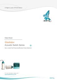
<strong>Microwave</strong> Smart Switch Series<br />
- Beam Blockage Detection -<br />
A higher level of performance
<strong>Microwave</strong> Smart Switch Series<br />
<strong>Manual</strong><br />
Rev 1.71, Sept 2013<br />
INTRODUCTION<br />
CONTENTS<br />
PROPRIETARY NOTICE<br />
The information contained in this publication<br />
is derived in part from proprietary and patent<br />
data. This information has been prepared for<br />
the express purpose of assisting operating and<br />
maintenance personnel in the efficient use of the<br />
instrument described herein. Publication of this<br />
information does not convey any rights to use or<br />
reproduce it, or to use for any purpose other than<br />
in connection with the installation, operation and<br />
maintenance of the equipment described herein.<br />
WARNING<br />
This instrument contains electronic components<br />
that are susceptible to damage by static<br />
electricity. Proper handling procedures must<br />
be observed during the removal, installation, or<br />
handling of internal circuit boards or devices:<br />
Handling Procedure:<br />
1. Power to unit must be removed prior to<br />
commencement of any work.<br />
2. Personnel must be grounded, via wrist strap<br />
or other safe, suitable means, before any<br />
printed circuit board or other internal devices<br />
are installed, removed or adjusted.<br />
3. Printed circuit boards must be transported<br />
in a conductive bag or other conductive<br />
container. Boards must not be removed from<br />
protective container until the immediate time<br />
of installation. Removed boards must be<br />
placed immediately in a protective container<br />
for transport, storage, or return to factory.<br />
Comments:<br />
This instrument is not unique in its content<br />
of ESD (electrostatic discharge) sensitive<br />
components. Most modern electronic designs<br />
contain components that ut ilize metal oxide<br />
technology (NMOS, CMOS, etc.). Experience<br />
has proven that even small amounts of static<br />
electricity can damage or destroy these<br />
devices. Damaged components, even though<br />
they appear to function properly, exhibit early<br />
failure.<br />
General Description, Features 3<br />
Typical Applications 4-5<br />
Dimensions 6-12<br />
Mounting 13-17<br />
Wiring<br />
- Smart Integral Version 18<br />
- Remote - <strong>Hawk</strong> Cable 19<br />
- Remote - Customer Cable 20<br />
- Cable extensions 21<br />
- Relay Functions 22<br />
- Cross Talk Prevention<br />
• 2 Units 23<br />
• More than 2 Units 24<br />
- Multidrop Connections 25<br />
- <strong>Hawk</strong>Link GSM 26<br />
- Test Terminal 27<br />
Setup Procedure<br />
- Smart Integral Version 28<br />
- Remote Version 32<br />
Remote Software Menus<br />
- Software Tree 35<br />
- Diagnostic Displays 36<br />
- QuickSet Menu 37<br />
- App Types 38<br />
- Advanced Menu 39<br />
- Relay 2 Actions 41<br />
Troubleshooting / Error Codes 43<br />
Safety Information 44<br />
Part Numbering 45<br />
Specifications 48<br />
Contact Information (back cover)<br />
2
<strong>Microwave</strong> Smart Switch Series<br />
<strong>Manual</strong><br />
Rev 1.71, Sept 2013<br />
GENERAL DESCRIPTION<br />
FEATURES<br />
Principle of Operation<br />
Beam blockage<br />
A beam of microwave energy passes from<br />
a sender to a separate receiver in bursts<br />
approximately 200 times per second. If the<br />
path between the sender and receiver is<br />
blocked by any object or material which absorbs<br />
or reflects microwave energy, then the<br />
receiver will not be able to detect the signal.<br />
The presence or absence of the signal at<br />
the receiver is used to switch a relay for<br />
indication or control purposes.<br />
<strong>Microwave</strong>s are small (Micro) radio waves<br />
transmitted from point to point hence the<br />
system setup of ‘sender’ and ‘receiver’ units.<br />
Note:<br />
For wet, dusty environments where<br />
build up issues of wet high dielectric<br />
material is prevalent <strong>Microwave</strong><br />
technology will have performance<br />
problems. <strong>Hawk</strong> recommends the<br />
<strong>Gladiator</strong> Acoustic Switch for these<br />
applications.<br />
• Wide beam pattern for easy alignment<br />
• LCD setup/diagnostics on remote amplifier<br />
• Ranges up to 200 meters (656 ft)<br />
• Simple ‘1-minute’ setup<br />
• Remote sensor or Smart Integral ‘all in<br />
one’ types<br />
• Relay outputs: Smart Integral (1) Remote (2)<br />
• Remote test function<br />
• Adjustable ON and OFF delays (0-20 sec)<br />
• Smart communication options: Gos<strong>Hawk</strong>,<br />
Modbus, HART, Profibus DP, DeviceNet<br />
• Remote GSM Connection option<br />
• Remote amplifier to sensor separation up<br />
to 500 m (1640 ft)<br />
• Bright visual status indication on sensors<br />
• Independent housing alignment after<br />
mounting sensors<br />
3
<strong>Microwave</strong> Smart Switch Series<br />
<strong>Manual</strong><br />
Rev 1.71, Sept 2013<br />
TYPICAL APPLICATIONS<br />
Blocked Chute Detection / Machine Anti-Collision<br />
Shiploader Luffing<br />
Control/Boom Protection<br />
Boom Protection<br />
Shiploader Protection<br />
Blocked Chute Protection<br />
4
<strong>Microwave</strong> Smart Switch Series<br />
<strong>Manual</strong><br />
Rev 1.71, Sept 2013<br />
TYPICAL APPLICATIONS<br />
Bulk Material Handling<br />
High/low and blocked<br />
chute detection<br />
Receiving Unit<br />
Receiver<br />
<strong>Microwave</strong> Product Flow Blocked<br />
Chute Detection<br />
Customer<br />
Supplied<br />
Mounting<br />
Sender<br />
Flange Mounted to a<br />
Isolated Permanant S<br />
Structure i.e.<br />
I-Beam,and Rail, etc<br />
High Vibration Applic<br />
<strong>Microwave</strong> should be<br />
from normal material<br />
Brac<br />
Process Plants<br />
Solid Level - Cyclone Bin<br />
High/low Level<br />
<strong>Gladiator</strong><br />
Receiver<br />
Note: Distance between<br />
microwave face and window<br />
should not exceed 75mm (3")<br />
for all applications<br />
(UHMW/PTFE HighWindows,<br />
Sight Glass, Ceramic<br />
<strong>Gladiator</strong><br />
Brick<br />
and Firebrick assemblies).<br />
Sender<br />
Sending Unit<br />
“Blocked Chute”<br />
Mount <strong>Microwave</strong> under<br />
pulley or out of main<br />
Stable Support system flow<br />
Structure<br />
Receiver<br />
Sender<br />
Low<br />
<strong>Gladiator</strong><br />
Hopper/Feeder (Not to Scale)<br />
Ceramic or Firebrick<br />
W/Antenna Bracket<br />
High Temp Area<br />
High Temperature<br />
Non Intrusive Switch<br />
High/Low level<br />
Blocked Chute<br />
Wave Guides<br />
GLADIATOR<br />
Remote<br />
5
<strong>Microwave</strong> Smart Switch Series<br />
<strong>Manual</strong><br />
Rev 1.71, Sept 2013<br />
DIMENSIONS<br />
SMART INTEGRAL MICROWAVE SYSTEM<br />
Standard Sender or Receiver<br />
Ø85 mm (3.3”)<br />
High Power Sender,<br />
Receiver or SRS Receiver<br />
Ø85 mm (3.3”)<br />
50 mm (2”)<br />
129.5 mm (5.1”)<br />
135.5 mm (5.3”)<br />
90 mm (3.5”)<br />
2 mm (0.078”)<br />
10 mm (0.4”)<br />
50 mm (2”)<br />
90 mm (3.5”)<br />
12 mm (0.5”)<br />
Ø88 mm (3.5”)<br />
Ø160 mm (6.3”)<br />
250 mm (9.8”)<br />
Ø165 mm (6.5”)<br />
Ø277 mm (10.9”)<br />
Standard Sender or Receiver Flange<br />
High power Sender / Receiver or SRS Flange<br />
160 mm (6.3”)<br />
135 mm (5.3”)<br />
8xØ22 mm<br />
Holes THRU<br />
160 mm (6.3”)<br />
Alignment<br />
marks<br />
4x10 mm holes<br />
Ø238 mm(9.3”)<br />
Ø88.5 mm (3.5”)<br />
Ø165 mm (6.3”)<br />
Ø277 mm (10.9”)<br />
Note: Remote and Smart Integral types use the same flange dimensions<br />
6
<strong>Microwave</strong> Smart Switch Series<br />
<strong>Manual</strong><br />
Rev 1.71, Sept 2013<br />
DIMENSIONS<br />
REMOTE MICROWAVE SYSTEM<br />
Amplifier Enclosure<br />
192.5 mm (7.6”)<br />
174 mm (6.9”)<br />
111.5 mm (4.4”)<br />
78 mm (3.1”)<br />
14 mm (0.6”)<br />
30.7 mm (1.2”)<br />
7.5 mm (0.3”)<br />
192.5 mm (7.6”)<br />
147 mm (5.8”)<br />
108 mm (4.3”)<br />
190 mm (7.5”)<br />
107 mm (4.2”)<br />
190 mm (7.5”)<br />
167.5 mm (6.6”)<br />
141.5 mm (5.6”)<br />
131.5 mm (5.2”)<br />
182.5 mm (7.2”)<br />
50 mm (2”)<br />
74 mm (2.9”)<br />
4 mm (0.2”)<br />
147 mm (5.8”)<br />
158 mm (6.2”)<br />
182.5 mm (7.2”)<br />
Standard Sender or Receiver<br />
Ø85 mm (3.3”)<br />
High Power Sender,<br />
Receiver or SRS Receiver<br />
Ø85 mm (3.3”)<br />
50 mm (2”)<br />
90 mm (3.5”)<br />
2 mm (0.078”)<br />
10 mm (0.4”)<br />
129.5 mm (5.1”)<br />
135.5 mm (5.3”)<br />
50 mm (2”)<br />
90 mm (3.5”)<br />
12 mm (0.5”)<br />
Ø88 mm (3.5”)<br />
Ø160 mm (6.3”)<br />
250 mm (9.8”)<br />
Ø165 mm (6.5”)<br />
Note: For Flange dimensions see page 5<br />
Ø277 mm (10.9”)<br />
7
<strong>Microwave</strong> Smart Switch Series<br />
<strong>Manual</strong><br />
Rev 1.71, Sept 2013<br />
DIMENSIONS<br />
ACCESSORIES<br />
Weldments to suit UHMW/Teflon windows<br />
Size A B C D E F G<br />
G<br />
3” 100<br />
(3.94”)<br />
3”<br />
NPT 22<br />
(0.87”)<br />
5<br />
(0.2”)<br />
92.5<br />
(3.64”)<br />
118<br />
(4.65”)<br />
4<br />
(0.16”)<br />
A<br />
B<br />
E<br />
F<br />
4” 125<br />
(4.92”)<br />
6” 190.4<br />
(7.5”)<br />
4”<br />
NPT 24.4<br />
(0.96”)<br />
6”<br />
NPT 40<br />
(3.94”)<br />
5<br />
(0.2”)<br />
5<br />
(0.2”)<br />
120<br />
(4.72”)<br />
175<br />
(6.89”)<br />
148<br />
(5.83”)<br />
223<br />
(8.78”)<br />
4<br />
(0.16”)<br />
11.2<br />
(0.44”)<br />
UHMW/Teflon Windows<br />
75mm (2.95")<br />
Ø6.5mm(0.25”)<br />
2 Places<br />
I<br />
C<br />
H<br />
D<br />
15mm (0.59")<br />
3” steel weldment: MA-0 3” stainless steel weldment MA-19<br />
4” steel weldment: MA-18 4” stainless steel weldment MA-22<br />
Size H I<br />
3” 3”<br />
NPT<br />
4” 4”<br />
NPT<br />
6” 6”<br />
NPT<br />
28.7<br />
(1.13”)<br />
35<br />
(1.38”)<br />
40<br />
(1.57”)<br />
3” UHMW window only MA-21<br />
4” UHMW window only MA-20<br />
3” UHMW window & weldment MA-3<br />
4” UHMW window & weldment MA-4<br />
6” UHMW window & weldment MA-5<br />
3” teflon window & weldment MA-6<br />
4” teflon window & weldment MA-7<br />
6” teflon window & weldment MA-8<br />
Weldments to suit Ceramic windows R<br />
J<br />
K<br />
Retainer for Ceramic Windows<br />
(Bundled with matching Weldment)<br />
U<br />
Ø6.3mm(0.25”)<br />
2 Places<br />
L<br />
M<br />
N<br />
O P Q<br />
Size J K L M N O P Q R<br />
3” 100<br />
(3.94”)<br />
4” 125<br />
(4.92”)<br />
3”<br />
NPT<br />
4”<br />
NPT<br />
Ceramic Windows<br />
(Bundled with matching Weldment)<br />
22<br />
(0.87”)<br />
24.4<br />
(0.96”)<br />
5<br />
(0.2”)<br />
5<br />
(0.2”)<br />
65<br />
(2.56”)<br />
90<br />
(3.54”)<br />
75<br />
(2.95”)<br />
101<br />
(3.98”)<br />
92.5<br />
(3.64”)<br />
120<br />
(4.72”)<br />
118<br />
(4.65”)<br />
148<br />
(5.83”)<br />
Size S T U V<br />
3” 75<br />
(2.95”)<br />
65<br />
(2.56”)<br />
3”<br />
NPT<br />
74.5<br />
(2.93”)<br />
4<br />
(0.16”)<br />
4<br />
(0.16”)<br />
T<br />
V<br />
4” 100<br />
(3.94”)<br />
90<br />
(3.54”)<br />
4”<br />
NPT<br />
100.5<br />
(3.96”)<br />
S<br />
12.3mm (0.48”) 11-12.7mm (0.43-0.5”)<br />
3” ceramic window & weldment MA-16<br />
4” ceramic window & weldment MA-17<br />
Unlisted parts not available separately<br />
8
<strong>Microwave</strong> Smart Switch Series<br />
<strong>Manual</strong><br />
Rev 1.71, Sept 2013<br />
DIMENSIONS<br />
ACCESSORIES<br />
Ceramic Tile Window Assembly<br />
MA-10<br />
Ceramic Time Mounting Assembly<br />
152.4mm (6.0")<br />
101.6mm<br />
(4.0")<br />
317.5mm (12.5")<br />
Ceramic Tile (alumina)<br />
101.6mm (4.0")<br />
152.4mm (6.0")<br />
25.4mm (1")<br />
9
<strong>Microwave</strong> Smart Switch Series<br />
<strong>Manual</strong><br />
Rev 1.71, Sept 2013<br />
DIMENSIONS<br />
ACCESSORIES<br />
Firebrick Window Assembly<br />
MA-9<br />
Firebrick Mounting Assembly<br />
228.6mm (9.0")<br />
114.3mm<br />
(4.5")<br />
215.9mm<br />
(8.5")<br />
419.1mm (16.5")<br />
50.8mm<br />
(2.0")<br />
Firebrick<br />
114.3mm<br />
(4.5")<br />
228.6mm (9.0")<br />
76.2mm<br />
(3.0")<br />
10
<strong>Microwave</strong> Smart Switch Series<br />
<strong>Manual</strong><br />
Rev 1.71, Sept 2013<br />
DIMENSIONS<br />
ACCESSORIES<br />
Example High Temperature Waveguide Parts<br />
*All Waveguide Parts available on special order only<br />
Waveguide<br />
WR90 Cone<br />
41mm<br />
(1.625")<br />
33mm<br />
(1.283")<br />
41mm<br />
(1.625")<br />
32mm<br />
(1.275")<br />
10mm<br />
(0.90")<br />
23mm<br />
(0.890")<br />
Waveguide WR90 Straight<br />
FB<br />
GTAW<br />
4mm Ø.172) ( Thru<br />
Typ 4 Pics<br />
33mm<br />
(1.283")<br />
"A"<br />
Note: "A" = Per Application<br />
Finish Per Application<br />
33mm (1.283")<br />
Waveguide WR90 Bend<br />
4mm (Ø .172) Thru<br />
Type 8 Pics 33mm (1.283")<br />
FB<br />
33mm<br />
(1.283")<br />
"A"<br />
GTAW<br />
FB<br />
Note: "A" = Per Application<br />
Finish Per Application<br />
11
<strong>Microwave</strong> Smart Switch Series<br />
<strong>Manual</strong><br />
Rev 1.71, Sept 2013<br />
DIMENSIONS<br />
ACCESSORIES<br />
Adjustable <strong>Microwave</strong> Bracket<br />
MA-12 - With UHMW Window<br />
MA-13 - With PTFE Window<br />
135mm (5.3")<br />
4 x 10mm (3/8")<br />
Mounting holes<br />
Ø<br />
225mm<br />
(8.85")<br />
120mm (4.72")<br />
148mm (5.83")<br />
336mm (13.2")<br />
Glass Window MA-1<br />
Flanged Pipe Mount MA-15<br />
300mm (11.8")<br />
2" N.P.T.<br />
19.9mm (0.78")<br />
6.3mm (0.25")<br />
135mm (5.31") 140mm (5.51")<br />
94mm<br />
(3.7")<br />
4 mounting holes 10mm (3/8")<br />
101mm<br />
(3.97")<br />
End closed<br />
with UHMW<br />
window<br />
Flanged pipe mount<br />
recommended for<br />
collision detection<br />
applications<br />
12
<strong>Microwave</strong> Smart Switch Series<br />
<strong>Manual</strong><br />
Rev 1.71, Sept 2013<br />
MOUNTING<br />
GENERAL GUIDELINES<br />
1. The microwave beam is a polarized form<br />
of energy. As such, it is necessary to align<br />
the units in the same spatial plane. If the<br />
units do not have the same orientation, the<br />
amount of received energy is diminished. At<br />
90° to each other, the detector is blind and<br />
cannot detect the beam. The actual angle<br />
of mounting is not relevant, so long as both<br />
the Sender & Receiver have the same angle<br />
and elevation. Flanges are marked with an<br />
alignment notch cut into one edge of the<br />
flange to assist in mounting correctly.<br />
2. When looking for a mounting location it<br />
is important to locate and mount the interior<br />
of the window/sensor face for each unit<br />
flush with the vessel wall and where minimal<br />
build-up will occur. The system can penetrate<br />
through generous amounts of buildup<br />
of various products, however, the better the<br />
position, the more reliably it will operate. A<br />
cavity in the vessel mount position where<br />
build up is possible will result in a ‘plug’<br />
forming in front of the beam path resulting in<br />
unit performance issues.<br />
3. <strong>Microwave</strong> energy cannot penetrate<br />
through steel linings or other conductive<br />
linings. You must cut a viewing hole and use<br />
an appropriate windowed weldment.<br />
4. For high vibration applications, it is<br />
necessary to isolate the electronics to keep<br />
them from long term damage. This is most<br />
often accomplished using 4” UHMW or<br />
Teflon windowed weldments in the vessel<br />
walls, and mounting the <strong>Microwave</strong> Sender<br />
and Receiver to a separate stable structure<br />
(I-beam, handrail) to isolate them from vibration.<br />
Isolation shock mounts can also be<br />
provided to help protect the electronics.<br />
5. For high temperature applications which<br />
exceed 65°C/150°F (precipitators, cement<br />
cyclones, etc.), it is necessary to ensure<br />
that the sensors always remain below<br />
65°C/150°F. This is normally achieved by<br />
installation of temperature resistant windows<br />
of ceramic or firebrick, and positioning<br />
of the Sender and Receiver in line with the<br />
windows, and set back far enough that their<br />
temperature remains below the given limit.<br />
Where this is impossible, it will be necessary<br />
to use remote mounting microwaves<br />
with waveguide assemblies. This allows<br />
the electronics to be placed in an area<br />
where ambient temperatures do not exceed<br />
the maximum allowable for operation. It is<br />
necessary to contact the factory for this last<br />
type of waveguide application.<br />
13
<strong>Microwave</strong> Smart Switch Series<br />
<strong>Manual</strong><br />
Rev 1.71, Sept 2013<br />
MOUNTING<br />
SPECIFIC APPLICATIONS<br />
1. When mounting to monitor the level<br />
of a flowing product such as coal, ore or<br />
wood chips, position the microwave path<br />
out of the direct product flow stream. If at all<br />
possible, go behind the flow stream or well<br />
in front of it. This will minimise any possibility<br />
of unwanted trips due to abnormal<br />
product flow blocking the beam. Always use<br />
the recommended setup for blocked chute<br />
detection.<br />
2. When using the system as a proximity<br />
switch such as truck detection the mounting<br />
arrangement is application dependent<br />
and must ensure proper operation even<br />
under worst case conditions.<br />
4. Mounting of a <strong>Microwave</strong> system on<br />
sloped vessel walls can be accomplished<br />
using the <strong>Microwave</strong> Adjustable Mount (MA-<br />
12 or MA-13). This system allows the microwaves<br />
to be mounted to a sloped surface<br />
and then adjusted horizontally for optimum<br />
performance and operation. The adjustable<br />
mount has an integral 4” weldment with<br />
UHMW polyethylene or PTFE (Teflon) window<br />
options. An option with the bracket is a<br />
vibration isolation kit (shock mounts) to help<br />
protect the electronics from damage. Each<br />
side wall of the vessel must not exceed 30<br />
degrees from the vertical centerline. To<br />
mount the adjustable bracket, simply cut a<br />
hole and weld the 4” weldment directly to<br />
the vessel, install the window, mount the<br />
microwave and adjust horizontally.<br />
Similar performance can be obtained by<br />
fabrication of fixed brackets which mount<br />
the Sender and Receiver in direct line with<br />
one another and aimed through the centre<br />
of two MA-4 windowed weldments.<br />
6. For boom protection / anti collision<br />
mounting the MA15 flange pipe should be<br />
used to assist in the reduction of beam<br />
spread over long distances. The units<br />
should be mounted with a 2 meter exclusion<br />
zone in mind for the beam path between<br />
the sender and receiver. Do not use Integral<br />
units for boom protection.<br />
See the dedicated <strong>Hawk</strong> <strong>Microwave</strong> alignment<br />
& setup procedure guide for further<br />
information about anti collision / boom<br />
protection application information<br />
www.hawkmeasure.com<br />
14
<strong>Microwave</strong> Smart Switch Series<br />
<strong>Manual</strong><br />
Rev 1.71, Sept 2013<br />
MOUNTING<br />
CORRECT MOUNTING ANGLE<br />
Correct Elevation<br />
Maximum Signal Strength to Receiver is indicated by maximum brightness<br />
of Green LED on Receiver.<br />
Sending Unit<br />
<br />
<strong>Microwave</strong> Beam<br />
Receiving Unit<br />
Incorrect Elevation<br />
Sending Unit<br />
Receiving Unit<br />
<br />
ALIGN SENDER AND RECEIVER<br />
Rotate so that Visual Alignment Guide is in the<br />
same position on both sender and receiver.<br />
<br />
<br />
!<br />
Correct rotational alignment is<br />
critical for correct performance<br />
15
<strong>Microwave</strong> Smart Switch Series<br />
<strong>Manual</strong><br />
Rev 1.71, Sept 2013<br />
MOUNTING<br />
MOUNTING WITH WINDOWED WELDMENTS<br />
Metal Bin/Chute Walls<br />
4” UHMW Windowed Weldment<br />
Sender<br />
Receiver<br />
Fabricated Bracket<br />
Attach fabricated brackets to separate structure<br />
if bin/chute walls are subject to high vibration<br />
BLOCKED CHUTE MOUNTING<br />
MAIN PRODUCT FLOW<br />
Receiving Unit<br />
Sending Unit<br />
Housing can be rotated<br />
within 200º after the<br />
mounting thread is<br />
tightened, to allow cable<br />
entries to face downwards<br />
or allow optimal cable<br />
clearance.<br />
Position blocked<br />
chute detectors<br />
to one side of<br />
main product flow<br />
16
<strong>Microwave</strong> Smart Switch Series<br />
<strong>Manual</strong><br />
Rev 1.71, Sept 2013<br />
MOUNTING<br />
INSTALLATION WITH ADJUSTABLE MOUNTING<br />
Product Flow<br />
Hopper/Feeder<br />
X<br />
X<br />
X = 30° Maximum<br />
Sending Unit<br />
Receiving Unit<br />
Isolation Mount<br />
Adjustable microwave mounting bracket<br />
MA-12 or MA-13 welded to vessel wall.<br />
UHMW (MA-12) or Teflon (MA-13) Window.<br />
17
<strong>Microwave</strong> Smart Switch Series<br />
<strong>Manual</strong><br />
Rev 1.71, Sept 2013<br />
WIRING<br />
SMART INTEGRAL SYSTEM<br />
Receiver<br />
Green Power/Signal<br />
strength/alignment indicator LED<br />
Blue Calibration/Error LED<br />
Red Relay Status LED<br />
Sender<br />
Green Power ON LED<br />
Red Transmitter enabled LED<br />
SENSITIVITY<br />
HI FSH CAL TEST<br />
DELAY<br />
Remove Plug-In<br />
terminal block for<br />
easier wiring.<br />
MICROWAVE SENDER<br />
INT 1 2 3<br />
PRESS<br />
PWR TX TO TEST<br />
1 2 3 4 5 6 7 8 9 10<br />
1 2 3 4 5 6 7 8 9 10<br />
The AC earth/ground cable<br />
must be connected to the<br />
ground screw inside the<br />
housing when using AC<br />
power.<br />
Hole for securing of<br />
optional identification tag<br />
M4 grounding screw<br />
If only one cable is used for both<br />
power and output signal, then the<br />
second entry port must be<br />
plugged or blinded. Every Smart<br />
receiver is supplied with two M20<br />
glands (or 3/4”NPT adaptors)<br />
mounted on the unit and one<br />
blind plug loose.<br />
**Ground the housing to<br />
vessel, if vessel is metallic.<br />
Ground the housing to<br />
plant ground, if vessel is<br />
non-metallic.<br />
**<br />
RECEIVER TERMINAL LAYOUT<br />
RELAY COMMS DC-IN AC-IN<br />
SENDER TERMINAL LAYOUT<br />
DC-IN<br />
AC-IN<br />
1. NC<br />
2. COM<br />
3. NO<br />
4. Test<br />
5. A<br />
6. B<br />
7. +<br />
-<br />
N<br />
8.<br />
9.<br />
10. L1<br />
1.<br />
2.<br />
3.<br />
4.<br />
5.<br />
6.<br />
7. +<br />
-<br />
N<br />
8.<br />
9.<br />
10. L1<br />
RS 485<br />
12-30VDC 80-260VAC<br />
12-30VDC 80-260VAC<br />
Terminals 1, 2, 3, 4, 5, 6 not used<br />
Note: AC power terminals may only be used when<br />
universal AC power supply option has been selected<br />
- see part numbers - AC terminals have no function in<br />
products without universal AC power option.<br />
18
<strong>Microwave</strong> Smart Switch Series<br />
<strong>Manual</strong><br />
Rev 1.71, Sept 2013<br />
WIRING<br />
REMOTE SYSTEM - HAWK SUPPLIED CABLE<br />
The black wire of <strong>Hawk</strong> supplied cable<br />
comes with one end GND and the other<br />
GND/SHLD together.<br />
The GND/SHLD end is a larger cable which<br />
has been heat shrunk. The GND only end is<br />
the same size as the other coloured cables.<br />
The GND/SHLD end must be connected<br />
to the amplifier and the GND end to the<br />
sender/receiver.<br />
Remote Receiver<br />
TERMINAL LAYOUT<br />
Remote Sender<br />
TERMINAL LAYOUT<br />
Green Power ON LED<br />
Red Transmitter<br />
enabled LED<br />
1.<br />
2.<br />
3.<br />
4. BROWN<br />
5. WHITE<br />
6. BLUE<br />
7. RED<br />
8. BLACK<br />
9.<br />
10.<br />
1.<br />
2.<br />
3.<br />
4. BROWN<br />
5.<br />
6.<br />
7. RED<br />
8. BLACK<br />
9.<br />
10.<br />
MICROWAVE SENDER<br />
INT 1 2 3<br />
PRESS<br />
PWR TX TO TEST<br />
Terminals 1, 2, 3, 9, 10 not used<br />
Terminals 1, 2, 3, 5, 6, 9, 10 not used<br />
Green Power/<br />
Signal strength/<br />
alignment indicator LED<br />
1 2 3 4 5 6 7 8 9 10<br />
Signal<br />
Status<br />
Remove Plug-In<br />
terminal block for<br />
easier wiring.<br />
Signal strength/<br />
alignment test<br />
point for volt<br />
meter connection<br />
1 2 3 4 5 6 7 8 9 10<br />
Hole for securing of<br />
optional identification tag<br />
Add wire<br />
between<br />
terminal 8<br />
and ground<br />
screw<br />
Add wire between<br />
terminal 8 and<br />
ground screw<br />
M4 grounding screw<br />
**Ground the housing to<br />
vessel, if vessel is metallic.<br />
Ground the housing to<br />
plant ground, if vessel is<br />
non-metallic.<br />
<strong>Gladiator</strong> Remote Amplifier<br />
Is<br />
+ –<br />
4-20mA (N/A)<br />
Note: AC power terminals may only be used when<br />
universal AC power supply option has been selected<br />
- see part numbers - AC terminals have no function in<br />
products without universal AC power option.<br />
RED<br />
BLACK<br />
BROWN<br />
SLAVE IN<br />
MASTER OUT<br />
TEST IN<br />
NC<br />
COM<br />
NO<br />
NC<br />
COM<br />
STRIP INSULATION<br />
NO<br />
9mm<br />
MIC-SENDER<br />
RED<br />
BLACK<br />
BLUE<br />
WHITE<br />
BROWN<br />
RELAY 1<br />
B<br />
A<br />
**<br />
– +<br />
RELAY 2<br />
16 17 18 19 20 21 22 23 24 25 26 27 28 29 30<br />
1 2 3 4 5 6 7 8 9 10 11 12 13 14 15<br />
N<br />
SENSOR COMMS DC-In AC-In*<br />
L1<br />
Relay 1 - Output Relay<br />
Relay 2 - FailSafe Relay<br />
AWG 22 -14<br />
(0.5 -1.5mm)<br />
User pliers to extract<br />
terminal blocks<br />
19
<strong>Microwave</strong> Smart Switch Series<br />
<strong>Manual</strong><br />
Rev 1.71, Sept 2013<br />
WIRING<br />
REMOTE SYSTEM - CUSTOMER SUPPLIED CABLE<br />
Remote Receiver<br />
TERMINAL LAYOUT<br />
Remote Sender<br />
TERMINAL LAYOUT<br />
Green Power ON LED<br />
Red Transmitter<br />
enabled LED<br />
1.<br />
2.<br />
3.<br />
4. BROWN<br />
5. WHITE<br />
6. BLUE<br />
7. RED<br />
8. BLACK<br />
9.<br />
10.<br />
1.<br />
2.<br />
3.<br />
4. BROWN<br />
5.<br />
6.<br />
7. RED<br />
8. BLACK<br />
9.<br />
10.<br />
MICROWAVE SENDER<br />
INT 1 2 3<br />
PRESS<br />
PWR TX TO TEST<br />
Terminals 1, 2, 3, 9, 10 not used<br />
Terminals 1, 2, 3, 5, 6, 9, 10 not used<br />
Green Power/<br />
Signal strength/<br />
alignment indicator LED<br />
1 2 3 4 5 6 7 8 9 10<br />
Signal<br />
Status<br />
1 2 3 4 5 6 7 8 9 10<br />
Remove Plug-In<br />
terminal block for<br />
easier wiring.<br />
Signal strength/<br />
alignment test<br />
point for volt<br />
meter connection<br />
SHIELD wire is<br />
NOT CONNECTED<br />
at terminal block -<br />
SHIELD is<br />
connected to<br />
grounding screw<br />
Hole for securing of<br />
optional identification tag<br />
M4 grounding screw<br />
<strong>Gladiator</strong> Remote Amplifier<br />
MIC-SENDER<br />
RELAY 1<br />
**<br />
RELAY 2<br />
RED<br />
BLACK<br />
BROWN<br />
SLAVE IN<br />
MASTER OUT<br />
TEST IN<br />
NC<br />
COM<br />
NO<br />
NC<br />
COM<br />
NO<br />
SHIELD wire is<br />
NOT CONNECTED<br />
at terminal block -<br />
SHIELD is<br />
connected to<br />
grounding screw<br />
**Ground the housing to<br />
vessel, if vessel is metallic.<br />
Ground the housing to<br />
plant ground, if vessel is<br />
non-metallic.<br />
Alternate cable type between Amplifier and Sensors<br />
6 or 8 conductor (5 used) shielded twisted pair instrument cable.<br />
Conductor size dependent on cable length.<br />
BELDEN 3120A, DEKORON or equivalent.<br />
Max: BELDEN 3120A = 500m (1640 ft). 3 pairs, 1 conductor not used.<br />
16 17 18 19 20 21 22 23 24 25 26 27 28 29 30<br />
Is<br />
1 2 3 4 5 6 7 8 9 10 11 12 13 14 15<br />
+ –<br />
4-20mA (N/A)<br />
RED<br />
BLACK<br />
BLUE<br />
WHITE<br />
BROWN<br />
Relay 1 - Output Relay<br />
Relay 2 - FailSafe Relay<br />
Connect BOTH GND<br />
AND SHIELD to ‘black’<br />
terminal at Amplifier<br />
end only<br />
B<br />
A<br />
– +<br />
N<br />
SENSOR COMMS DC-In AC-In*<br />
L1<br />
User pliers to extract<br />
terminal blocks<br />
Alternate Cable Colour Equivalents<br />
<strong>Hawk</strong> Belden 3120A Dekoron (Pair 4 not used )<br />
Pair 1<br />
Red<br />
Black<br />
Red<br />
Black<br />
White 1<br />
Black 1<br />
Note: AC power terminals may only be used when<br />
universal AC power supply option has been selected<br />
- see part numbers - AC terminals have no function in<br />
products without universal AC power option.<br />
Pair 2<br />
Pair 3<br />
White<br />
Blue<br />
Brown<br />
---<br />
Yellow<br />
Green<br />
Brown<br />
White (not used)<br />
White 2<br />
Black 2<br />
White 3<br />
Black 3 (not used)<br />
20
RED<br />
BROWN<br />
BLACK<br />
SHIELD<br />
RED<br />
BLACK<br />
RED<br />
BLACK<br />
BLUE<br />
BROWN<br />
WHITE<br />
BROWN<br />
BLUE<br />
BLACK<br />
RED<br />
WHITE<br />
BROWN<br />
SHIELD<br />
<strong>Microwave</strong> Smart Switch Series<br />
<strong>Manual</strong><br />
Rev 1.71, Sept 2013<br />
WIRING<br />
JUNCTION BOX / CABLE EXTENSION<br />
Cable shields<br />
connect to<br />
BLACK<br />
at AMPLIFIER end<br />
<strong>Gladiator</strong> <strong>Microwave</strong><br />
Amplifier<br />
MIC-SENDER<br />
Re-connect<br />
Cable Shield<br />
to Black<br />
SENSOR<br />
Cable<br />
Shield<br />
Seperate<br />
Black/Shield<br />
Re-connect<br />
Cable Shield<br />
to Black<br />
CUSTOMER<br />
JUNCTION BOX.<br />
DO NOT GROUND<br />
SHIELD CABLE AT<br />
JUNCTION BOX<br />
Cable<br />
Shield<br />
Seperate<br />
Black/Shield<br />
SENDER TERMINAL CONNECTIONS<br />
RECEIVER TERMINAL CONNECTIONS<br />
4. BROWN<br />
7. RED<br />
8. BLACK<br />
4. BROWN<br />
5. WHITE<br />
6. BLUE<br />
7. RED<br />
8. BLACK<br />
SHIELD CABLE<br />
NOT CONNECTED<br />
TO SENDER/RECEIVER<br />
SENDER<br />
RECEIVER<br />
Alternate cable type between Amplifier and Sensors<br />
6 or 8 conductor (5 used) shielded twisted pair instrument cable.<br />
Conductor size dependent on cable length.<br />
BELDEN 3120A, DEKORON or equivalent.<br />
Max: BELDEN 3120A = 500m (1640 ft). 3 pairs, 1 conductor not used.<br />
Max: DEKORON IED183AA004 = 350m (1150 ft). 4 pairs, 3 conductors not used.<br />
21
WIRING<br />
RELAY FUNCTIONS<br />
<strong>Microwave</strong> Smart Switch Series<br />
Level Switch Contact Action<br />
Relay - for Smart Integral Probe Version (Set Relay<br />
Action selection switch pages 27 and 28)<br />
Relay 1 - for Remote Version (Set ‘Relay Action’<br />
parameter pages 32 and 35)<br />
FailSafe Low<br />
FSL<br />
Relay Action<br />
<strong>Manual</strong><br />
Rev 1.71, Sept 2013<br />
FailSafe High<br />
FSH (default)<br />
State 1<br />
1 2 3<br />
NC COM NO<br />
1 2 3<br />
NC COM NO<br />
Relay Status<br />
Smart Integral<br />
Receiver terminal<br />
numbers<br />
Remote Amplifier<br />
terminal function<br />
labels<br />
LED Status<br />
Material level rising<br />
State 2<br />
1 2 3<br />
NC COM NO<br />
1 2 3<br />
NC COM NO<br />
Material detected<br />
State 3<br />
1 2 3<br />
NC COM NO<br />
1 2 3<br />
NC COM NO<br />
Material level falling<br />
POWER FAILURE<br />
1 2 3<br />
NC COM NO<br />
1 2 3<br />
NC COM NO<br />
FailSafe Switch Contact Action<br />
Relay 2 - Remote version only. For<br />
Smart Integral units, the Test terminal<br />
can act as a solid state output with a<br />
similar function.<br />
(see page 25)<br />
POWER FAILURE<br />
OR<br />
INTERNAL FAILURE<br />
SYSTEM OPERATING<br />
NORMALLY<br />
NC COM NO NC COM NO<br />
NC COM NO<br />
NC COM NO<br />
22
<strong>Microwave</strong> Smart Switch Series<br />
<strong>Manual</strong><br />
Rev 1.71, Sept 2013<br />
WIRING<br />
CROSS-TALK PREVENTION - FOR 2 UNITS (REMOTE ONLY)<br />
Within the menu for each unit, select Master<br />
for one system and select Slave for the<br />
second system. These settings are located<br />
in the Advanced menu then under Operation<br />
Mode.<br />
Operation Mode has 3 selections:<br />
1. Remote<br />
2. Master<br />
3. Slave<br />
MASTER*<br />
Receiver 1<br />
Sender 1<br />
The wiring needs to be as indicated, with a<br />
shielded connection cable between the two<br />
units. The selected Master has a connection<br />
to Master Out and GND/DC- and the<br />
selected Slave has a connection to Slave In<br />
and GND/DC-.<br />
The shield is conncted to the Ground or<br />
24Vdc (-ve) terminal on each unit.<br />
Receiver 2<br />
SLAVE*<br />
Sender 2<br />
GLADIATOR MICROWAVE REMOTE AMPLIFIER - MASTER<br />
GLADIATOR MICROWAVE REMOTE AMPLIFIER - SLAVE<br />
MIC-SENDER<br />
RED<br />
BLACK<br />
BROWN<br />
SLAVE IN<br />
MASTER OUT<br />
TEST IN<br />
RELAY 1<br />
NC<br />
COM<br />
NO<br />
RELAY 2<br />
NC<br />
COM<br />
NO<br />
MIC-SENDER<br />
RED<br />
BLACK<br />
BROWN<br />
SLAVE IN<br />
MASTER OUT<br />
TEST IN<br />
RELAY 1<br />
NC<br />
COM<br />
NO<br />
RELAY 2<br />
NC<br />
COM<br />
NO<br />
16 17 18 19 20 21 22 23 24 25 26 27 28 29 30<br />
16 17 18 19 20 21 22 23 24 25 26 27 28 29 30<br />
Is<br />
1 2 3 4 5 6 7 8 9 10 11 12 13 14 15<br />
+ –<br />
RED<br />
BLACK<br />
BLUE<br />
WHITE<br />
BROWN<br />
B<br />
A<br />
– +<br />
N<br />
L1<br />
4-20mA (N/A) SENSOR COMMS DC-In AC-In*<br />
Is<br />
1 2 3 4 5 6 7 8 9 10 11 12 13 14 15<br />
+ –<br />
RED<br />
BLACK<br />
BLUE<br />
WHITE<br />
BROWN<br />
B<br />
A<br />
– +<br />
N<br />
L1<br />
4-20mA (N/A) SENSOR COMMS DC-In AC-In*<br />
Ground<br />
* Software selected<br />
MICROWAVE MASTER/SLAVE CALIBRATION<br />
Step 1: Place the Master unit into CAL mode by<br />
pressing the CAL button.<br />
Step 2: Ensure that the Slave system, which you<br />
intend to Calibrate, has been set to Slave mode.<br />
Step 3: To calibrate the Slave system select the<br />
CalMounting option, which can be found in the<br />
Quickset menu and select YES.<br />
Step 5: To calibrate the Master system select the<br />
CalMounting option, which can be found in the<br />
Quickset menu and select YES.<br />
Step 6: Press the RUN button to resume operation.<br />
The calibration process is now complete for<br />
a Master/Slave system.<br />
Step 4: Press the RUN button to resume operation.<br />
23
B<br />
A<br />
N<br />
<strong>Microwave</strong> Smart Switch Series<br />
<strong>Manual</strong><br />
Rev 1.71, Sept 2013<br />
B<br />
A<br />
N<br />
Is<br />
WIRING<br />
CROSS-TALK PREVENTION - FOR MORE THAN 2 UNITS<br />
(REMOTE ONLY)<br />
Operation is similar to cross-talk prevention<br />
for 2 units except that the GMSEQ <strong>Microwave</strong><br />
sequencer will operate as the Master and each<br />
individual <strong>Microwave</strong> unit will operate as a Slave.<br />
The sequencer will control and step from CH1 to<br />
CH2 to CH3 to CH4 then return to CH1.<br />
The maximum time between scans if 4 channels<br />
are connected is approx. 3ms. More than one<br />
unit can be connected to each channel, note that<br />
each unit connected to the same channel will be<br />
part of the same slave ‘sequence’ in the pulsing<br />
Within the menu of each individual <strong>Microwave</strong><br />
unit, select Slave mode in the Advanced Menu<br />
under Operating Mode.<br />
Receiver 1<br />
SLAVE 1<br />
Sender 1<br />
GLADIATOR MICROWAVE REMOTE AMPLIFIER - SLAVE<br />
GLADIATOR MICROWAVE REMOTE AMPLIFIER - SLAVE<br />
Is<br />
Receiver 2<br />
SLAVE 2<br />
Sender 2<br />
MIC-SENDER<br />
+ –<br />
Tx<br />
SLAVE IN<br />
MASTER OUT<br />
Test in<br />
RELAY 1<br />
NC<br />
COM<br />
NO<br />
NC<br />
RELAY 2<br />
COM<br />
NO<br />
MIC-SENDER<br />
+ –<br />
Tx<br />
SLAVE IN<br />
MASTER OUT<br />
Test in<br />
RELAY 1<br />
NC<br />
COM<br />
NO<br />
NC<br />
RELAY 2<br />
COM<br />
NO<br />
CURRENT<br />
SENSOR<br />
COMMS<br />
DC-IN<br />
AC-IN<br />
CURRENT<br />
SENSOR<br />
COMMS<br />
DC-IN<br />
AC-IN<br />
+ –<br />
RED<br />
BLACK<br />
BLUE<br />
WHITE<br />
BROWN<br />
– +<br />
L1<br />
24 VDC 80-265 VAC<br />
+ –<br />
RED<br />
BLACK<br />
BLUE<br />
WHITE<br />
BROWN<br />
– +<br />
L1<br />
24 VDC 80-265 VAC<br />
GMSEQ <strong>Microwave</strong> Sequencer Terminal<br />
CH1 CH2 CH3 CH4<br />
com<br />
Tx<br />
com<br />
Tx<br />
com<br />
Tx<br />
com<br />
Tx<br />
TO<br />
SLAVE 3<br />
MICROWAVE MASTER/SLAVE CALIBRATION<br />
TO<br />
SLAVE 4<br />
Step 1: Place the Sequencer unit into CAL unlock<br />
1 mode by pressing the CAL button on the sequencer<br />
unit.<br />
Step 2: Ensure that the systems that you intend<br />
to calibrate is set Operation Mode’ as ‘Slave’.<br />
The Sequencer unit will operate as the Master to<br />
control the pulsing sequence.<br />
Step 3: Remove the wire connection to the Slave<br />
In terminal, which connects between the slave<br />
system and the sequencer unit.<br />
Step 4: To calibrate the Slave system select the<br />
CalMounting option, which can be found in the<br />
Quickset menu and select YES.<br />
Step 5: After calibration is done, re-connect the<br />
Slave In cable between the slave system and the<br />
sequencer unit.<br />
Step 6: Repeat steps 1 to 5 for each of the slave<br />
systems connected to the sequencer.<br />
Step 7: Press the RUN button on the sequencer<br />
and all of the slave units. The process is now<br />
complete.<br />
* Note for best performance the sequencer setting<br />
is shown below. Do not adjust these settings.<br />
• On time – 240μs<br />
• Off time – 700μs<br />
24
HI FSH<br />
ON<br />
HI FSH<br />
ON<br />
CAL TEST<br />
ON<br />
1 2 1 2<br />
LO FSL OFF OFF<br />
1 2 3 4 5 6 7 8 9 10<br />
HI FSH<br />
ON<br />
1 2 3 4 5 6 7 8 9 10<br />
CAL TEST<br />
ON<br />
1 2 1 2<br />
LO FSL OFF OFF<br />
1 2 1 2<br />
LO FSL OFF OFF<br />
1 2 3 4 5 6 7 8 9 10<br />
CAL TEST<br />
ON<br />
HI FSH<br />
ON<br />
CAL TEST<br />
ON<br />
1 2 1 2<br />
LO FSL OFF OFF<br />
1 2 3 4 5 6 7 8 9 10<br />
HI FSH<br />
ON<br />
HI FSH<br />
ON<br />
CAL TEST<br />
ON<br />
1 2 1 2<br />
LO FSL OFF OFF<br />
1 2 3 4 5 6 7 8 9 10<br />
CAL TEST<br />
ON<br />
1 2 1 2<br />
LO FSL OFF OFF<br />
1 2 3 4 5 6 7 8 9 10<br />
<strong>Microwave</strong> Smart Switch Series<br />
<strong>Manual</strong><br />
Rev 1.71, Sept 2013<br />
WIRING<br />
MULTIDROP CONNECTIONS<br />
Multidrop GPRS Connection*<br />
SENSITIVITY<br />
DELAY<br />
SENSITIVITY<br />
DELAY<br />
<strong>Hawk</strong>Link<br />
HLRUG6<br />
GPRS modem<br />
A B Gnd<br />
A B Gnd<br />
A B Gnd<br />
Laptop or PC Communications using<br />
PCMCIA card or wired (PSTN) modem<br />
and remote GSM/CDMA connection<br />
with Gos<strong>Hawk</strong> software.<br />
Multidrop Connection Using <strong>Hawk</strong>Link USB*<br />
SENSITIVITY<br />
DELAY<br />
SENSITIVITY<br />
DELAY<br />
A B Gnd<br />
A B Gnd<br />
A B Gnd<br />
White<br />
Blue<br />
Black<br />
<strong>Hawk</strong>link<br />
USB<br />
Laptop or PC Communications using<br />
<strong>Hawk</strong>link USB or RS485 / 232 converter<br />
with Gos<strong>Hawk</strong> software.<br />
Multidrop Connection to PLC/DCS/SCADA*<br />
SENSITIVITY<br />
DELAY<br />
SENSITIVITY<br />
DELAY<br />
A B Gnd<br />
A B Gnd<br />
A B Gnd<br />
PLC / DCS / SCADA for Remote<br />
Communication with Modbus.<br />
* Wiring installation should follow<br />
RS-485 standards for layout and<br />
termination.<br />
25
WIRING<br />
RS 485<br />
1 2<br />
12-30VDC<br />
*<br />
80-265VAC<br />
<strong>Microwave</strong> Smart Switch Series TO<br />
Connect shield to<br />
DC “-” only at this end.<br />
Separate AC power supply<br />
for the GSM module<br />
or<br />
DC power<br />
supply<br />
HAWK UNIT<br />
HAWKLINK GSM - CONNECTING POWER AND COMMS<br />
<strong>Manual</strong><br />
Rev 1.71, Sept 2013<br />
HAWKLINK MODEM TERMINAL BLOCK<br />
B<br />
2 WIRE LOOP POWERED DEVICES<br />
ID 1 ID 2 ID 3 ID 4 ID 5<br />
A<br />
GND<br />
B<br />
A<br />
GND<br />
B<br />
A<br />
GND<br />
B<br />
A<br />
GND<br />
B<br />
A<br />
GND<br />
B<br />
MASTER<br />
A<br />
GND<br />
B<br />
PC POWER NETWORK 12-30VDC 90-265 VAC<br />
A<br />
GND<br />
OUT<br />
IN<br />
B<br />
A<br />
N<br />
L1<br />
<strong>Hawk</strong> Unit<br />
-<br />
MASTER PC POWER NETWORK 12-30VDC 90-265 VAC<br />
B A<br />
Wire Foil<br />
1 2 3<br />
SHIELDED<br />
TWISTED-PAIR<br />
1 2 3<br />
Copper Shield<br />
PVC<br />
Connect shield to<br />
Jacket<br />
DC “-” only at this end.<br />
BOTTOM TOP<br />
COMMS<br />
12-30VDC<br />
PLC CONNECTION STANDARD CONNECTION LOOP POWER CONNECTION<br />
B<br />
PLC A<br />
GND<br />
HAWK<br />
UNIT<br />
1<br />
HAWK<br />
UNIT<br />
2<br />
HAWK<br />
UNIT<br />
Nx<br />
B<br />
A<br />
GND<br />
B<br />
A<br />
GND<br />
B<br />
A<br />
GND<br />
MASTER<br />
B A GND<br />
NETWORK<br />
B A -<br />
NETWORK<br />
B A -<br />
B<br />
A<br />
GND<br />
B<br />
A<br />
GND<br />
B<br />
A<br />
GND<br />
HAWK<br />
UNIT<br />
1<br />
HAWK<br />
UNIT<br />
2<br />
HAWK<br />
UNIT<br />
Nx<br />
LOOP<br />
UNIT 1<br />
MASTER<br />
B<br />
A<br />
B<br />
A<br />
B<br />
A<br />
GND<br />
GND<br />
GND<br />
B<br />
A<br />
B<br />
A<br />
Each terminal block<br />
ID 1 to 5 wired to<br />
individual loop<br />
powered units<br />
ID 1 ID 2 ID 3 ID 4 ID 5<br />
GND<br />
GND<br />
OUT<br />
IN<br />
B<br />
A<br />
GND<br />
B<br />
A<br />
B<br />
A<br />
GND<br />
PC POWER NETWORK 12-30VDC 90-265 VAC<br />
N<br />
MASTER PC POWER NETWORK 12-30VDC 90-265 VAC<br />
B<br />
LOOP<br />
UNIT 5<br />
A<br />
B<br />
A<br />
GND<br />
GND<br />
L1<br />
BOTTOM TOP<br />
26
<strong>Microwave</strong> Smart Switch Series<br />
<strong>Manual</strong><br />
Rev 1.71, Sept 2013<br />
WIRING<br />
TEST TERMINAL FUNCTION SELECTION<br />
The test terminal has two potential modes of operation for Smart Integral units and always<br />
operates in the test input mode for Remote units. Remote units have a separate, failsafe<br />
relay contact, which is always functional.<br />
TEST INPUT MODE<br />
(Test switch must be in ‘TEST’ (ON) position on Smart Integral Units - function always enabled on Remote Units)<br />
Test terminal acts as an input for remote testing of the instrument’s switching function. Used<br />
to check for malfunction of unit from a remote position, PLC, SCADA etc. For more information<br />
see page 29.<br />
TEST INPUT FROM PLC/SCADA/DCS DIGITAL OUTPUT<br />
Terminal Block<br />
PLC / SCADA / DCS Output<br />
Test<br />
OPERATOR CONTROLLED PRESS TO TEST<br />
!<br />
PLC/SCADA/DCS GROUND MUST<br />
CONNECT BACK TO GLADIATOR<br />
GROUND OR DC ‘-’ TERMINALS<br />
Terminal Block<br />
Externally provided<br />
test button<br />
Test<br />
FAILSAFE OUTPUT MODE<br />
(Test switch must be in the ‘OFF’ position - default setting)<br />
!<br />
EXTERNAL PUSH BUTTON GROUND<br />
MUST CONNECT BACK TO GLADIATOR<br />
GROUND OR DC ‘-’ TERMINALS<br />
Test terminal will provide an output which is able to switch an external failsafe relay or PLC/SCADA/DCS<br />
input. During normal system operation this terminal will internally switch a solid state (transistor) output to<br />
ground (or DC ‘-’). If power fails or an internal system failure occurs, the terminal will act as an open circuit.<br />
To switch an external relay<br />
To a PLC input<br />
Test<br />
+12-24Vdc<br />
Coil rating<br />
500mW max<br />
or 50mA max<br />
Relay will turn on during<br />
normal system operation<br />
or off in failed or unpowered<br />
conditions.<br />
Test<br />
27<br />
max 50mA<br />
12-24Vdc<br />
Pull up<br />
PLC<br />
SCADA<br />
DCS Input<br />
Input will detect ‘0’ state during normal system<br />
operation, or ‘1’ in failed or unpowered conditions.
<strong>Microwave</strong> Smart Switch Series<br />
<strong>Manual</strong><br />
Rev 1.71, Sept 2013<br />
SETUP PROCEDURE<br />
FUNCTIONALITY LAYOUT - SMART INTEGRAL SENDER<br />
3<br />
1<br />
4<br />
INT 1<br />
MICROWAVE SENDER<br />
2 3<br />
PRESS<br />
TO TEST<br />
PWR TX<br />
5<br />
REM 0<br />
0 0<br />
1 2 3 4 5 6 7 8 9 10<br />
2<br />
REMOVABLE SENDER TERMINAL BLOCK<br />
DC-IN AC-IN<br />
-<br />
+<br />
N<br />
L1<br />
6<br />
1.<br />
2.<br />
3.<br />
4.<br />
5.<br />
6.<br />
7.<br />
8.<br />
9.<br />
10.<br />
7-30VDC 80-260VAC<br />
Terminals 1, 2, 3, 4, 5, 6 not used<br />
1 Smart Integral / Remote mode selection switch (INT/REM)<br />
2 Green LED - power status, continuously on when power supply is OK<br />
3 Red LED - transmitter enabled<br />
4 Pulse rate setting switches (see table below)<br />
Press to test button - interupts signal transmission for system testing.<br />
5<br />
Simulates the effects of breaking of microwave beam.<br />
6 Removable terminal block - plug in type<br />
Switch Settings<br />
INT/REM<br />
1, 2, 3<br />
Sender pulse<br />
rate selection<br />
0 = OFF<br />
1 = ON<br />
Set to INT for Smart Integral types<br />
1 2 3<br />
0 0 0 45 Pulses per sec<br />
0 0 1 44<br />
0 1 0 42<br />
0 1 1 41<br />
1 0 0 40<br />
1 0 1 39<br />
1 1 0 38<br />
1 1 1 37 - Default for INT<br />
The pulse rate may be changed to minimize<br />
the potential for cross-talk if multiple units are<br />
in the same operational area. If cross-talk is<br />
likely to occur, it is strongly recommended<br />
to use Remote type units and employ the<br />
cross-talk prevention schemes for 2 units or<br />
the multi sequence connection for more than<br />
2 units using a separate GMSEQ sequencing<br />
unit. Cross-talk prevention and sequencing for<br />
Remote units are detailed on pages 20 & 21.<br />
28
<strong>Microwave</strong> Smart Switch Series<br />
<strong>Manual</strong><br />
Rev 1.71, Sept 2013<br />
SETUP PROCEDURE<br />
FUNCTIONALITY LAYOUT - SMART INTEGRAL RECEIVER<br />
9<br />
3<br />
6<br />
12<br />
4<br />
SENSITIVITY<br />
signal<br />
HI FSH CAL TEST<br />
ON<br />
ON<br />
1 2 1 2<br />
LO FSL OFF OFF<br />
1 2 3 4 5 6 7 8 9 10<br />
DELAY<br />
1<br />
5<br />
2<br />
8<br />
REMOVABLE RECEIVER TERMINAL BLOCK<br />
RELAY COMMS DC-IN AC-IN<br />
10<br />
7<br />
11<br />
1. NC<br />
2. COM<br />
3. NO<br />
4. Test<br />
A<br />
B<br />
5.<br />
6.<br />
7. +<br />
8.<br />
9. N<br />
10. L1<br />
RS 485 7-30VDC 80-260VAC<br />
-<br />
Functionality Description (bold is default)<br />
1<br />
2<br />
3<br />
4<br />
5<br />
Mounting Calibration switch CAL/OFF<br />
Test input function select TEST/OFF<br />
Relay action selection<br />
switch<br />
FSH - FailSafe High<br />
FSL - FailSafe Low<br />
HI / LO sensitivity switch<br />
LO default. LO = less sensitivty.<br />
Lo for blocked chute detection<br />
Delay Potentiometer (0-20 sec)<br />
(0.1 sec. at minimum position)<br />
6<br />
7<br />
8<br />
9<br />
10<br />
11<br />
Sensitivity Potentiometer<br />
Anti-clockwise (low) for blocked chute detection<br />
RED LED: Relay status<br />
ON when relay coil is energised<br />
GREEN LED: Power / Received signal strength.<br />
Brightness varies with strength of received signal.<br />
BLUE LED:<br />
Blinking indicates calibration function is on.<br />
Continuously ON indicates failed calibration.<br />
AC Ground - must be used for<br />
AC powered installations<br />
Removable terminal block - plug in type<br />
12 Signal voltage test point<br />
29
<strong>Microwave</strong> Smart Switch Series<br />
<strong>Manual</strong><br />
Rev 1.71, Sept 2013<br />
SETUP PROCEDURE<br />
SMART INTEGRAL VERSION<br />
!<br />
1. Mount the units in their actual position<br />
1.1 If units are AC powered ensure proper grounding is<br />
connnected to ground screw.<br />
2. Make sure that the material or target is not blocking<br />
the path between sender and receiver.<br />
3. Turn the power on<br />
The green LED on the sender and receiver will stay<br />
on permanently to indicate that power is on. Green<br />
LED on receiver varies in brightness with strength of<br />
received signal.<br />
4. Sender (GMRS): Ensure the REM/INT DIP switch<br />
is selected to the INT position and the remaining<br />
switches (1, 2, 3) are all selected to OFF.<br />
5. Select the required relay action<br />
The Relay can switch ‘ON’ (FSL) or ‘OFF’ (FSH) as<br />
the microwave beam is blocked. Set the relay action<br />
selection switch position depending on your requirements.<br />
FSH is recommended (ordinarily on/energised,<br />
switches off/DEN during blocked conditions).<br />
6. Select the sensitivity<br />
There are two adjustments controlling the sensitivity of<br />
the switch point:<br />
6.1 The ‘HI/LO’ sensitivity DIP switch is used as<br />
the primary sensitivity setting. Select LO sensitivity<br />
for Blocked Chute detection. Select LO If build-up<br />
is expected over sensors or with strongly absorptive<br />
materials or targets. Select HI sensitivity for clean<br />
environments and lighter/less absorptive material or<br />
targets. LO recommended for most applications.<br />
Recommended Settings for<br />
Blocked Chute applications<br />
6.2 The sensitivity potentiometer<br />
Turning the pot fully counter-clockwise factory recommended<br />
for blocked chute applications. If operating<br />
in HI mode set the pot to 12 o’clock. In this mode you<br />
can turning the pot clockwise to reduce the amount of<br />
beam blockage required for switching and vice versa.<br />
7. Select the time delay<br />
Full anti clockwise is minimum (0.1 seconds). Full<br />
clockwise is maximum (20 seconds). Adjust as<br />
required allowing time to avoid possible nuisance trips.<br />
The selected delay will be used for both an ON delay<br />
and an OFF delay.<br />
8. Perform a CAL mount<br />
Do not proceed with this step unless the material or<br />
target position is well beneth the line between the<br />
sender and receiver.<br />
Switch the Mounting Calibration switch on the Receiver<br />
unit to ‘CAL’ (ON) position. The Blue LED will blink to<br />
indicate that mounting calibration is now in progress.<br />
Wait 5-10 sec, then switch the mounting calibration<br />
switch to ‘OFF’ position. The blue LED will switch off<br />
after successfull calibration. If it stays on this indicates<br />
there was a calibration error. If this is the case please<br />
check that the path between sender and receiver is<br />
clear and alignment is correct then try the calibration<br />
again. If mounting calibration was successful the blue<br />
LED should be off and the Green LED should be ON.<br />
9. Switch check<br />
If required block the Sender with a steel plate to check<br />
relay action & time delay. The green LED will dim when<br />
the <strong>Microwave</strong> beam begins to be blocked.<br />
You can also press the ‘TEST’ button on the Sender to<br />
simulate a blocked chute condition and thus trigger the<br />
relay action.<br />
Note: Integral type <strong>Microwave</strong> systems should not<br />
be used for anti collision detection / boom protection.<br />
Contact <strong>Hawk</strong> for information about the remote type<br />
systems.<br />
30
<strong>Microwave</strong> Smart Switch Series<br />
<strong>Manual</strong><br />
Rev 1.71, Sept 2013<br />
SETUP PROCEDURE - REMOTE VERSION<br />
FUNCTIONALITY LAYOUT<br />
REMOTE AMPLIFIER<br />
4<br />
1<br />
1<br />
Calibrate button<br />
2<br />
Run button<br />
3<br />
Down button<br />
4<br />
Up button<br />
5<br />
Relay LEDs 1 and 2<br />
3<br />
RELAY 1<br />
RELAY 2<br />
STATUS A<br />
STATUS B<br />
6 Display (LCD with backlight)<br />
5<br />
6<br />
7<br />
2<br />
7 Status LEDs A and B<br />
- Status A flashes with signal transmission of a unit in<br />
Remote or Master mode.<br />
- Status B flashes with signal transmission of a unit in<br />
Master or Slave mode.<br />
REMOTE RECEIVER<br />
REMOTE RECEIVER TERMINAL BLOCK<br />
TRANSDUCER<br />
8<br />
REMOTE<br />
STATUS<br />
1. 2. 3. 4. 5. 6. 7. 8. 9. 10.<br />
1 2 3 4 5 6 7 8 9 10<br />
9<br />
BROWN<br />
WHITE<br />
BLUE<br />
RED<br />
BLACK<br />
Terminals 1, 2, 3, 9, 10 not used.<br />
8<br />
GREEN LED: Power / Received signal strength.<br />
Brightness varies with strength of received signal.<br />
9<br />
Removable terminal block - plug in type<br />
31
<strong>Microwave</strong> Smart Switch Series<br />
<strong>Manual</strong><br />
Rev 1.71, Sept 2013<br />
SETUP PROCEDURE<br />
FUNCTIONALITY LAYOUT - REMOTE SENDER<br />
3<br />
1<br />
4<br />
INT 1<br />
MICROWAVE SENDER<br />
2 3<br />
PRESS<br />
TO TEST<br />
PWR TX<br />
5<br />
REM 0<br />
0 0<br />
REMOVABLE SENDER TERMINAL BLOCK<br />
1 2 3 4 5 6 7 8 9 10<br />
2<br />
1.<br />
2.<br />
3.<br />
4. BROWN<br />
5.<br />
6.<br />
7. RED<br />
8. BLACK<br />
9.<br />
10.<br />
6<br />
Terminals 1, 2, 3, 5, 6, 9, 10 not used<br />
1 Smart Integral / Remote mode selection switch (INT/REM)<br />
2 Green LED - power status, continuously on when power supply is OK<br />
3 Red LED - transmitter enabled<br />
4 Pulse rate setting switches (settings have no function for Remote units)<br />
5<br />
Press to test button - interupts signal transmission for system testing.<br />
Simulates the effects of breaking of microwave beam.<br />
6 Removable terminal block - plug in type<br />
Switch Settings<br />
INT/REM<br />
1, 2, 3<br />
Sender pulse<br />
rate selection<br />
Set to REM for Remote types<br />
Settings has no function for<br />
remote types.<br />
32
<strong>Microwave</strong> Smart Switch Series<br />
<strong>Manual</strong><br />
Rev 1.71, Sept 2013<br />
SETUP PROCEDURE<br />
REMOTE VERSION<br />
1. Mount the unit in its actual position<br />
(see mounting procedure - pages 12-16)<br />
Make sure that external ground wire is connected<br />
between the outside ground screw on the <strong>Gladiator</strong><br />
housing and the roof/wall/side of the silo/tank/vessel/chute.<br />
(For non metallic tanks make sure that<br />
external ground wire is connected between the<br />
same outside ground screw on the housing and the<br />
general plant ground potential.)<br />
2. Check where the actual level or target is relative<br />
to the sensors<br />
Make sure that the material or target is not blocking<br />
the path between sender and receiver.<br />
UnLock<br />
0<br />
Press<br />
CAL<br />
Press<br />
Press<br />
QuickSet<br />
CAL<br />
App Type<br />
CAL<br />
Press<br />
CAL<br />
Cal Mounting<br />
Yes / No<br />
Press CAL<br />
Yes<br />
Press CAL<br />
Switch Point<br />
75%<br />
Press<br />
CAL<br />
Press CAL<br />
Delay Adjust<br />
2.0S<br />
Press CAL<br />
0.1S<br />
Press CAL<br />
Relay Action<br />
FailSafe Hi<br />
Press<br />
CAL<br />
FailSafe Hi<br />
Press FailSafe Low<br />
Twice<br />
RUN<br />
!<br />
33<br />
3. Ensure that the mode selection switch on the<br />
transmitter is set to REM (OFF). See point 1 page 31.<br />
4. Turn the power on<br />
The display will turn on and the fail-safe relay will<br />
switch. The display will scroll through the following<br />
messages: <strong>Hawk</strong>, Amp SerialNo, Type, Amp Soft<br />
Ver, Device ID, SensorSerial, SensorModel, Sens<br />
SoftVer, Sensor Addrs, <strong>Gladiator</strong> System Amp.<br />
The unit will then go into operational mode displaying<br />
‘Switch’ with a % value. This % value represents<br />
the changing amount of signal loss between<br />
sender and receiver.<br />
5. Simple “1-minute” Setup - Follow the flow<br />
chart<br />
Choose Application Type<br />
Alignment - For Aligning the unit at long range. Unit is set to 1.2V signal (~48% switch<br />
value), move the unit face to get the volt reading high (2.4V will be the maximum<br />
reading or 0% switch value). Calibrate & re-select this mode and repeat till you cannot<br />
improve the alignment.<br />
Blocked Chute - Configures the unit for blocked chute applications<br />
Boom Protection - Configures the unit for anti collision applications<br />
Switch - Allows selection of Sensitivity% for standard switch application.<br />
Density - Special Density measurement mode. See App Types for further information<br />
Cancel Influence of Mounting<br />
Do not proceed with this step unless the material or target position is well beneth<br />
the line between the sender and receiver.<br />
Select ‘Yes’ to start the mounting calibration. ‘Wait’ will be displayed during the<br />
calibration for up to 30 seconds. Unit is now able to cancel the influence of the<br />
mounting. The % reading on the back lit display has been zeroed with the existing<br />
process conditions and the measurement history log has been cleared.<br />
Always calibrate the unit after changing Application type.<br />
Select the Switch point<br />
The output relay will switch at the entered % value. The default value of 76% will be<br />
suitable for detecting most media. For detection of products which are less absorbent of<br />
<strong>Microwave</strong> energy, select a lower % value and vice versa. For highly absorbent materials,<br />
almost any setting will work, but higher % settings will be more immune to build up.<br />
When the level or target falls below the sensors the relay will switch back at half of the<br />
entered switch point % value (when the beam is no longer broken).<br />
Select the Time Delay<br />
Set the time to be used for both switch on and switch off delays<br />
Select the required relay action<br />
The Relay can switch ‘ON’ or ‘OFF’ as the microwave beam is blocked and switch<br />
‘ON’ or ‘OFF’ in response to an instrument failure (see below). Set the parameter<br />
to FailSafe Low or FailSafe Hi depending on your requirements.
<strong>Microwave</strong> Smart Switch Series<br />
<strong>Manual</strong><br />
Rev 1.71, Sept 2013<br />
SOFTWARE MENU<br />
REMOTE AMPLIFIER<br />
ENTERING DATA<br />
All software adjustments are achieved via the four PUSHBUTTONS on the front<br />
panel.<br />
In Run Mode<br />
(A) Press and hold - interrupts normal operations and allows access<br />
to software menu headings.<br />
In Calibrate Mode<br />
(B) Steps into a menu selection to allow editing (down one level)<br />
(C) Saves selected value and moves onto the next menu item.<br />
In Run Mode<br />
(A) Scrolls up through operating diagnostics on display LCD.<br />
In Calibrate Mode<br />
(B) Scrolls up through software parameters when browsing the<br />
menus.<br />
(C) Increases display value when editing a parameter.<br />
In Run Mode<br />
(A) Scrolls down through operating diagnostics on LCD display.<br />
In Calibrate Mode<br />
(B) Scrolls down through software parameters when browsing the<br />
menus.<br />
(C) Decreases display value when editing a parameter.<br />
In Run Mode<br />
(A) Hides diagnostics if they are in view and returns to the standard<br />
running display.<br />
In Calibrate Mode<br />
(B) Steps out of a menu or selection (up one level). Parameter value<br />
will be stored automatically when stepping up.<br />
(C) Returns to running mode from the top level menu.<br />
34
<strong>Microwave</strong> Smart Switch Series<br />
<strong>Manual</strong><br />
Rev 1.71, Sept 2013<br />
FLOW CHART<br />
SOFTWARE TREE<br />
Press<br />
Sensor Value<br />
0.0%<br />
CAL<br />
To Calibrate<br />
Normal Running Display<br />
Press to view unit<br />
operation diagnostics<br />
On first start up there is<br />
no security code protection.<br />
Press<br />
UnLock<br />
0<br />
CAL<br />
Press<br />
Press<br />
Press<br />
To QuickSet<br />
QuickSet<br />
Advanced<br />
flow chart CAL<br />
CAL To Advanced<br />
flow chart<br />
See page 37 See page 38<br />
QuickSet Menu<br />
Advanced Menu<br />
covers all parameters covers less commonly<br />
required for standard used or advanced<br />
setups.<br />
parameters.<br />
Press<br />
RUN<br />
to return to normal operation<br />
35
<strong>Microwave</strong> Smart Switch Series<br />
<strong>Manual</strong><br />
Rev 1.71, Sept 2013<br />
FLOW CHART<br />
DIAGNOSTIC DISPLAYS (Remote type only)<br />
Sensor Value<br />
0.0%<br />
SW On 75.0%<br />
0.0%<br />
SW Off 50.0%<br />
0.0%<br />
Max 99.8%<br />
0.0%<br />
Min 0.0%<br />
0.0%<br />
Delay 0.1s<br />
0.0%<br />
Temp: 22.4C<br />
0.0%<br />
Normal<br />
0.0%<br />
Signal 2.40V<br />
0.0%<br />
Percentage above<br />
which the Relay<br />
will be in State 2*.<br />
Percentage below<br />
which the Relay<br />
will be in State 1*.<br />
}<br />
Max/Min captured<br />
Sensor Value % since<br />
Last history log reset,<br />
or last Cal Mounting<br />
operation<br />
Current switch<br />
delay time<br />
Current temperature<br />
inside housing<br />
(ºCelsius)<br />
Status<br />
Normal / CommRetry<br />
Received Signal strength<br />
The diagnostic displays appear on the<br />
top line of the LCD, after pressing the Up<br />
or Down push button when the <strong>Gladiator</strong><br />
<strong>Microwave</strong> switch is in its normal running<br />
mode.<br />
The diagnostics provide the user with<br />
valuable performance feedback on how the<br />
instrument is performing whilst in operation.<br />
The measured reading Sensor Value (%)<br />
continues to be displayed on the second<br />
line of the LCD during diagnostic viewing<br />
on the top line. Ouput relays will continue to<br />
operate during diagnostic viewing.<br />
Pressing RUN several times returns the unit<br />
into normal operation.<br />
*Switch points are refered to as ‘On’ and<br />
‘Off’ to reflect the most simply understood<br />
performance in FailSafe Low mode. Actual<br />
relay state may be different according to<br />
setting of relay action (see page 19).<br />
CommErr 1 -> unit has lost communications<br />
with the receiver.<br />
Fail 1 - No comms available.<br />
Gain 10.2%<br />
0.0%<br />
Noise 0.04V<br />
0.0%<br />
Current Gain% value.<br />
In Blocked Chute mode this will increase<br />
when product passes in front of the sensor.<br />
The unit has a maximum possible gain% of ~94%<br />
Background Noise received<br />
Remote<br />
0.0%<br />
Device operating mode<br />
Remote/Master/Slave<br />
36
<strong>Microwave</strong> Smart Switch Series<br />
<strong>Manual</strong><br />
Rev 1.71, Sept 2013<br />
QUICKSET MENU<br />
Parameter Description Options<br />
App Type (see next page for<br />
full App Type descriptions)<br />
Select application pre-set.<br />
This automatically configures<br />
the unit to the recommended<br />
settings for each<br />
specificapplication.<br />
Density<br />
Switch<br />
Boom Protect<br />
Blocked Chute<br />
Alignment<br />
Cal Mounting<br />
Switch Point<br />
On Delay Adj<br />
Relay1Action<br />
Lock Code<br />
Note you must perform a<br />
Cal Mount after changing or<br />
selecting App Type<br />
Performs a Cal Mount in<br />
which the unit automatically<br />
configures itself based on<br />
the selected App Type and<br />
the mounting environment.<br />
This is the switch on / off<br />
sensor value % for relay<br />
actions<br />
Set on delay time for the<br />
first relay. If using the 2nd<br />
relay in cleaner / maintenance<br />
mode 1/2 of this<br />
value will be the duration of<br />
the relay timer<br />
Adjust the Relay action<br />
to be energised or de-energised<br />
during normal<br />
operation<br />
Set a lock code to prevent<br />
unauthorised access<br />
Yes / No<br />
Auto - 75% (on) 50% (off)<br />
<strong>Manual</strong> (set in Advanced)<br />
Adjustable in seconds<br />
FailSafe Hi<br />
FailSafe Low<br />
Default 0<br />
37
<strong>Microwave</strong> Smart Switch Series<br />
<strong>Manual</strong><br />
Rev 1.71, Sept 2013<br />
APP TYPES<br />
Software Rev 740 and higher<br />
App Type Description Sub Menu<br />
Density (see Density<br />
Setup Guide<br />
below)<br />
Switch<br />
Boom Protection<br />
Blocked Chute<br />
Alignment<br />
Density is the new App Type which allows<br />
customers to measure variation in the amount<br />
of <strong>Microwave</strong> energy blocked and absorbed<br />
by in application. The variance is represented<br />
by a 4-20mA analog output. Note: Relay1 as<br />
a switch function is disabled while the Density<br />
application is selected.<br />
Sets the unit to a standard switch mode with<br />
adjustable sensitivity<br />
Sets the unit to Boom Protection mode. This<br />
can also be used for machinery or object<br />
detection<br />
Sets the unit for blocked chute mode. Note<br />
that this mode may be unsuitable for very low<br />
dieletric materials.<br />
A special mode for aligning units over long<br />
range. After performing a Cal Mount and<br />
running the unit it will indicate half signal /<br />
approximately 50%. Improving the alignment<br />
will reduce the %. Re-calibrate if the %<br />
reaches 0. After using this mode you must<br />
select a normal app type.<br />
HiSpan%<br />
This is the 20mA reference point. This<br />
can be Viewed, Autoset or set to a<br />
Custom value. This value will always be<br />
a 10-100% with 10% the most sensitive<br />
100% suited to measure the indicate the<br />
widest variation<br />
Sensitivity%<br />
A high value will make the unit more<br />
sensitive to switching and responding to<br />
lighter materials. A low value will make<br />
the unit more resilliant and ignore dust<br />
/ build up.<br />
Density Setup Guide<br />
1. Select ‘Density’ App Type<br />
2. Perform a CAL MOUNT<br />
3. Press RUN several times to restart the<br />
unit<br />
This will be the 4mA reference point for the<br />
analogue<br />
Note: You must RUN the unit before proceeding<br />
with the next step<br />
To set the 20mA reference point you can<br />
either:<br />
4. Enter a specific ‘HighSpan%’ (10-100%)<br />
or;<br />
5. Start the process you wish to measure.<br />
When the desired density of product is between<br />
the sender & receiver you can enter<br />
the Quickset menu and run ‘Autoset’. This<br />
sets the condition to 20mA / 100%.<br />
If Autoset returns ‘Failed’ you either did not<br />
press RUN after the CAL MOUNT to set the<br />
4mA point or the <strong>Microwave</strong> pulses are not<br />
blocked by a high enough density which the<br />
unit can measure.<br />
38
<strong>Microwave</strong> Smart Switch Series<br />
<strong>Manual</strong><br />
Rev 1.71, Sept 2013<br />
FLOW CHART<br />
ADVANCED MENU<br />
Advanced<br />
Default values/settings<br />
in bold and underlined<br />
Switch Mode<br />
Auto<br />
CAL<br />
Auto<br />
(view only)<br />
Auto - Factory default values. Switch On 75%, Switch Off 50%<br />
<strong>Manual</strong> - ‘Switch On’ and ‘Switch Off’ values can be edited in <strong>Manual</strong><br />
mode.<br />
<strong>Manual</strong><br />
(editable) *Only possible if manual selected<br />
CAL<br />
Switch On<br />
76%<br />
CAL CAL Relay switch point On (Default 75%)<br />
*Output relay in ‘State 2’ above this value.<br />
Switch Off<br />
71%<br />
CAL CAL Relay switch point Off (Default 50%)<br />
*Output relay in ‘State 1’ below this value.<br />
Relay2Action CAL See ‘Relay 2’<br />
View Log<br />
CAL<br />
CAL<br />
Yes<br />
View history log of instrument<br />
% and temperature Yes / No<br />
No<br />
Min Sensor %<br />
0.0%<br />
Minimum Sensor % since last<br />
Reset Log (not adjustable).<br />
Max Sensor %<br />
99.4%<br />
Maximum Sensor % since last<br />
Reset Log (not adjustable).<br />
Min Temp<br />
20.0C<br />
Minimum temperature value since<br />
last Reset Log (not adjustable).<br />
Max Temp<br />
26.9C<br />
Maximum temperature value since<br />
last Reset Log (not adjustable).<br />
Continued next<br />
page (Reset Log)<br />
*Switch points are refered to as ‘On’ and ‘Off’ to<br />
reflect the most simply understood performance in FailSafe Low<br />
mode. Actual relay state may be different according<br />
to setting of relay contact action (see page 19).<br />
39
<strong>Microwave</strong> Smart Switch Series<br />
<strong>Manual</strong><br />
Rev 1.71, Sept 2013<br />
FLOW CHART<br />
ADVANCED MENU (CON’T)<br />
From previous page<br />
Reset Log<br />
No<br />
Comms Type<br />
Modbus<br />
CAL<br />
CAL<br />
CAL<br />
CAL<br />
Reset history log<br />
(Yes / No)<br />
Log will automatically reset when Cal Mounting is used in<br />
QuickSet to cancel mounting influences and re-zero the % reading.<br />
Modbus<br />
HART<br />
Profibus DP<br />
DeviceNet<br />
Selection should not be changed<br />
unless required hardware is<br />
present.<br />
(see part numbers - page 43-45)<br />
Device ID<br />
1<br />
CAL<br />
CAL<br />
1-255<br />
Baud Rate<br />
19200<br />
CAL<br />
CAL<br />
1200<br />
4800<br />
9600<br />
19200<br />
38400<br />
57600<br />
Default values/settings<br />
in bold and underlined<br />
Back Light<br />
On<br />
CAL<br />
CAL<br />
Display Backlight<br />
On/Off<br />
Opertng Mode<br />
Remote<br />
CAL<br />
CAL<br />
Selection of device operating mode when used in installations requiring<br />
cross-talk prevention.<br />
Remote, Master, Slave<br />
Display Span<br />
Span 0<br />
CAL<br />
CAL<br />
Not Adjustable<br />
Display ProbeAVG Span<br />
23<br />
CAL<br />
CAL<br />
Averaging of measurement samples. A smaller number gives faster<br />
response and a larger number is more stable.<br />
Default 2<br />
LoadDefaults<br />
Yes / No<br />
CAL<br />
CAL<br />
Reset to factory defaults<br />
You will be prompted Yes / No for both the amplifier and sensors seperately<br />
InputVoltChk<br />
Yes / No<br />
CAL<br />
CAL<br />
Turns on voltage failsafe check<br />
If connected power is below minimum specification the unit can trigger its<br />
failsafe relay. When off unit will display ‘V in fail’.<br />
40
<strong>Microwave</strong> Smart Switch Series<br />
<strong>Manual</strong><br />
Rev 1.71, Sept 2013<br />
RELAY 2 ACTIONS<br />
Concept<br />
The <strong>Gladiator</strong> Amplifier has received a<br />
firmware update to utilise the Relay 2 as<br />
a trigger mechanism to notify the user or<br />
activate a cleaning system based on time<br />
or conditions within the application which<br />
require cleaning.<br />
There are three software options using<br />
two diffferent concepts. The first concept is<br />
based on total Gain used and the second is<br />
based on a Time interval.<br />
The options are located in the Advanced<br />
menu as a sub menu for Relay2Action.<br />
The selectable software options are as<br />
follows:<br />
[Maintnce Chk] - The unit will switch on the<br />
relay when total Gain is greater than the<br />
CleanGainHigh % - the relay will switch off<br />
when Gain falls below CleanGainLow %.<br />
[GainOpt Clng] - When total Gain exceeds<br />
the CleanGainHigh point the unit activates<br />
the relay for 1/2 of the On Delay time and<br />
then switches off. The unit will then count<br />
the Clean Time interval time before repeat<br />
the process until total Gain is below Clean-<br />
GainLow point.<br />
Setup Example - Time Based<br />
In ‘Quickset’ Set ‘On Delay’ to 4.0 seconds -<br />
this will provide a 2.0 second water blast.<br />
In ‘Advanced’ set ‘Relay2Action to ‘TimeOpt-<br />
Cln’ with a ‘Clean Timer’ of 30min.<br />
Every 30 minutes the sensors will be<br />
sprayed for 2 seconds.<br />
Setup Example - Gain Based<br />
In ‘Quickset’ Set ‘On Delay’ to 4.0 seconds -<br />
this will provide a 2.0 second water blast.<br />
In ‘Advanced’ set ‘Relay2Action to ‘GainOpt-<br />
Cln’ with a ‘CleanGainHi’ of 80%, ‘Clean-<br />
GainLo’ of 70% and ‘Clean Timer’ to 5.0min<br />
This will trigger the water spray for 2<br />
seconds when Gain goes above 80%. The<br />
spray will repeat every 5 minutes until Gain<br />
goes below 70%. You can view Gain while<br />
the unit is running by using the arrow key to<br />
locate the diagnostic display<br />
[TimeOpt Clng] - At every Clean Time interval<br />
the unit will switch on the relay for 1/2 of<br />
the On Delay time and then switch off.<br />
41
<strong>Microwave</strong> Smart Switch Series<br />
<strong>Manual</strong><br />
Rev 1.71, Sept 2013<br />
RELAY 2 ACTIONS<br />
Note: Requires GSA unit with software revision 7.40 or later<br />
To set spray duration for Gain and Time options (1/2 of On Delay).<br />
Sensor Value<br />
CAL<br />
Unlock 0<br />
CAL<br />
Quickset<br />
CAL<br />
App Type<br />
Cal Mount<br />
Switch Point<br />
On Delay Adj<br />
On Delay Adj<br />
CAL<br />
On Delay Adj<br />
CAL<br />
Off Delay Adj<br />
*Edit*<br />
Relay Action<br />
CAL<br />
to save<br />
Min 3.0 seconds<br />
To set Relay 2 action for one of Time, Gain or Maintenance options.<br />
Sensor Value<br />
CAL<br />
Unlock 0<br />
CAL<br />
Quickset<br />
Advanced<br />
CAL<br />
Switch Mode<br />
Relay2Action<br />
View Log<br />
Reset Log<br />
Comms Type<br />
ProbeAVG<br />
Initilize TX<br />
LoadDefaults<br />
CAL<br />
TimeOpt Cln<br />
CAL<br />
Clean Time<br />
GainOpt Cln Maintnce Chk Relay2<br />
Failsafe<br />
CAL<br />
CAL<br />
CleanGainHi CleanGainHi<br />
CAL<br />
Clean Time<br />
*Edit*<br />
CAL<br />
to save<br />
CAL<br />
CleanGainHi<br />
*Edit*<br />
CAL<br />
CleanGainLo<br />
CAL<br />
CleanGainHi<br />
*Edit*<br />
CAL<br />
CleanGainLo<br />
CAL<br />
CleanGainLo<br />
*Edit*<br />
CAL<br />
Clean Time<br />
CAL<br />
CleanGainLo<br />
*Edit*<br />
CAL<br />
to save<br />
CAL<br />
Clean Time<br />
*Edit*<br />
CAL<br />
to save<br />
Other Relay2 Actions<br />
Relay 2 - Sets the 2nd relay to mirror the first relay action<br />
Failsafe - Sets the relay to trigger for a failsafe condition such as sender/reciever fail or<br />
voltage problem<br />
42
<strong>Microwave</strong> Smart Switch Series<br />
<strong>Manual</strong><br />
Rev 1.71, Sept 2013<br />
TROUBLESHOOTING<br />
Error 01: Amplifier/Transmitter can not<br />
communicate with sender/receiver.<br />
Error No 01 is displayed on power up with<br />
a reset loop or after unit has successfully<br />
operated and subsequently failed.<br />
Check wiring terminals for a loose or<br />
incorrect connection (including junction<br />
box/cable extensions). Check the cables for<br />
any signs of damage. Ensure any customer<br />
supplied cable meets <strong>Hawk</strong> specifications.<br />
Ensure correct power is applied to the<br />
correct terminals. DC only version units will<br />
not support AC.<br />
Use a multimeter to check voltage supply for<br />
the Remote Sender & Receiver on the red/<br />
black labeled terminals of the Amplifier. You<br />
should get approximately as below:<br />
Sender<br />
+/- 24.0V<br />
Receiver:<br />
+/- 9.4V<br />
Ensure the Sender is set to the correct<br />
mode (integral or remote). This is set by the<br />
INT / REM switch on the Sender facia.<br />
Error 02: Communication data corruption<br />
between Transmitter and Transducer.<br />
It can be a result of noise in data lines or<br />
one of data lines (white or blue wires) being<br />
open circuit.<br />
1. Make sure wiring is correct especially<br />
look to the screen (earth).<br />
Error 03: Incorrect comms module selected<br />
(eg Profitbus, FF)<br />
Error 04: Amplifier is programmed with<br />
incorrect software. Contact your local<br />
support.<br />
Relays & LCD intermittently dimming<br />
and dropping out.<br />
Check incoming voltage with a multimeter. If<br />
unstable and dropping below 8V the unit is<br />
not getting enough power.<br />
If AC powered put a multimeter over the<br />
DC +/- terminals. The unit generates a DC<br />
voltage in these terminals if powered by AC.<br />
This should read at least 8V consistently. If<br />
this is unstable and dropping below 7V while<br />
your incoming AC is stable there is likely<br />
a problem with the internal power supply.<br />
Contact your local distributor or <strong>Hawk</strong>.<br />
Note:<br />
For wet, dusty environments where<br />
build up issues of wet high dielectric<br />
material is prevalent <strong>Microwave</strong><br />
technology will have performance<br />
problems. <strong>Hawk</strong> recommends the<br />
<strong>Gladiator</strong> Acoustic Switch for these<br />
applications.<br />
43
<strong>Microwave</strong> Smart Switch Series<br />
<strong>Manual</strong><br />
Rev 1.71, Sept 2013<br />
SAFETY INFORMATION<br />
FCC REGULATIONS<br />
Qualifications<br />
The Federal Communications Commission<br />
imposes strict requirements on radiating<br />
sources such as the GSA, GMSB, GMSHB,<br />
GMRR, GMRRH, GMRRS, GMS, GMSH,<br />
GMSR, GMSRH <strong>Microwave</strong> Systems. This<br />
unit is tested to, and meets these requirements,<br />
which include operating frequency<br />
and stability, harmonic and spurious<br />
generations and power output. The <strong>Hawk</strong><br />
<strong>Gladiator</strong> <strong>Microwave</strong> System complies with<br />
FCC Rules Part 15 for industrial controls.<br />
No licenses or approvals are required to use<br />
the system.<br />
Requirements<br />
(A) OSHA - 10mW/cm2of radiated power.<br />
(B) ANSI - 5mW/cm2 of radiated power.<br />
The <strong>Hawk</strong> <strong>Gladiator</strong> <strong>Microwave</strong> Systems<br />
have approximately 20µW/cm2 of radiated<br />
power.<br />
Note: The <strong>Hawk</strong> <strong>Microwave</strong> Pulse Systems<br />
are well below the stringent safety standards<br />
required by both the above governing bodies.<br />
It is regarded as a SAFE level control<br />
and may be used with no special precautions.<br />
44
<strong>Microwave</strong> Smart Switch Series<br />
<strong>Manual</strong><br />
Rev 1.71, Sept 2013<br />
PART NUMBERING<br />
REMOTE VERSION<br />
Remote Amplifier<br />
GSA Remote <strong>Gladiator</strong> System Amplifier<br />
Housing<br />
S Polycarbonate<br />
Power Supply<br />
B 12-30VDC<br />
C 30-48VDC and 48-90VAC (30-48VDC)<br />
U 12-30VDC and 90-260VAC<br />
Output Options<br />
S 2 relays with Modbus<br />
X 2 relays with Modbus plus 4-20mA Analogue for Density measurement<br />
GSA S U S<br />
Remote Sender/Receiver<br />
GMSB <strong>Gladiator</strong> <strong>Microwave</strong> Sender<br />
GMSHB <strong>Gladiator</strong> <strong>Microwave</strong> Sender High Power<br />
GMRR <strong>Gladiator</strong> <strong>Microwave</strong> Remote Receiver<br />
GMRRH <strong>Gladiator</strong> <strong>Microwave</strong> Remote Receiver High Power<br />
Frequency<br />
1 10 GHz<br />
Facing Material<br />
0 UHMW Polyethylene<br />
W Wave guide connector<br />
Housing Material<br />
1 Aluminium / Mild Steel<br />
2 Full stainless steel GMSB/GMRR<br />
3 Full stainless steel GMSHB/GMRRH<br />
Output Option<br />
X Not required<br />
Approval Standard<br />
X Not Required<br />
A22 ATEX Gas/Dust (Grp II Cat 3 GD T65C IP67)<br />
GMSB 1 0 1 X X<br />
45
<strong>Microwave</strong> Smart Switch Series<br />
<strong>Manual</strong><br />
Rev 1.71, Sept 2013<br />
PART NUMBERING<br />
SMART INTEGRAL VERSION<br />
GMS<br />
GMSH<br />
GMSR<br />
GMSRH<br />
<strong>Gladiator</strong> <strong>Microwave</strong> Sender<br />
<strong>Gladiator</strong> <strong>Microwave</strong> Sender High Power<br />
<strong>Gladiator</strong> <strong>Microwave</strong> Smart (Integral) Receiver<br />
<strong>Gladiator</strong> <strong>Microwave</strong> Smart (Integral) Receiver High Power<br />
Power Supply<br />
B 12-30VDC<br />
C 30-48VDC and 48-90VAC (30-48VDC)<br />
U 12-30VDC and 90-260VAC<br />
Frequency<br />
1 10 GHz<br />
Facing Material<br />
UHMW Polyethylene<br />
W Wave guide connector<br />
Housing Material<br />
1 Aluminium / Mild Steel<br />
2 Full stainless steel GMS/GMSR<br />
3 Full stainless steel GMSH/GMSRH or GMSRS<br />
Output Option<br />
X Not required (Sender units)<br />
S Switch, 1 output relay with Modbus (Receiver units)<br />
Approval Standard<br />
X Standard CE approved<br />
A22 ATEX Gas/Dust (Grp II Cat 3 GD T65C IP67)<br />
GMSR B 1 0 1 S X<br />
46
<strong>Microwave</strong> Smart Switch Series<br />
<strong>Manual</strong><br />
Rev 1.71, Sept 2013<br />
PART NUMBERING<br />
ACCESSORIES<br />
CA-GMR Pre-cut cable for remote sender or receiver unit<br />
10 10m cable each<br />
20 20m cable each<br />
30 30m cable each<br />
50 50m cable each<br />
100 100m cable each (contact factory)<br />
CA-GMR 10M<br />
MA Mounting Accessory<br />
Type<br />
0 3” Steel Weldment only each<br />
3 3” UHMW Window & Weldment each<br />
4 4” UHMW Window & Weldment each<br />
5 6” UHMW Window & Weldment each<br />
6 3” PTFE Window & Weldment each<br />
7 4” PTFE Window & Weldment each<br />
8 6” PTFE Window & Weldment each<br />
9 9’ x 4.5” Firebrick Window Assembly each<br />
10 6” x 4” Ceramic Tile Window Assembly each<br />
12 Adjustable mounting (UHMW window) each<br />
13 Adjustable mounting (PTFE window) each<br />
14 Remote wave guide Assembly<br />
15 Focaliser Tube / Flanged Pipe Mount<br />
16 3” Ceramic window & weldment each<br />
17 4” Ceramic window & weldment each<br />
18 4” Steel Weldment only each<br />
19 3” Stainless steel Weldment only each<br />
20 4” UHMW Window only each<br />
21 3” UHMW Window only each<br />
22 4” Stainless steel Weldment only each<br />
25 Stainless Steel Focaliser Tube / Flanged Pipe Mount<br />
MA 3<br />
GMSEQ <strong>Gladiator</strong> <strong>Microwave</strong> Sequencer<br />
Power Supply<br />
B 12-30VDC<br />
C 30-48VDC and 48-90VAC (30-48VDC)<br />
U 12-30VDC and 90-260VAC<br />
GMSEQ U<br />
HL <strong>Hawk</strong>Link 3G modem<br />
Type<br />
R Remote stand alone system mounted in a remote enclosure<br />
c/w antenna.<br />
Power Supply<br />
B 12-30VDC<br />
U 12-30VDC and 90-260VAC<br />
Network Type<br />
G3 3G Multiband<br />
Network Type<br />
S3 Australian Sim Card expires after 3 month<br />
S12 Australian Sim Card expires after 12 month<br />
X Sim Card not required<br />
HL R U G3 X<br />
47
<strong>Microwave</strong> Smart Switch Series<br />
<strong>Manual</strong><br />
Rev 1.71, Sept 2013<br />
SPECIFICATIONS<br />
Operating Voltage<br />
• Smart Integral 12-30VDC / Remote 12-30 VDC (residual<br />
ripple no greater than 100mV)<br />
• Smart Integral 80-260Vac / Remote 90-260Vac<br />
50/60Hz<br />
Power Consumption<br />
•
Contacts<br />
Rev 1.71 Sept 2013<br />
<strong>Hawk</strong> <strong>Measurement</strong> Systems (Head Office)<br />
15-17 Maurice Court<br />
Nunawading VIC 3131<br />
Australia<br />
Phone: +61 3 9873 4750<br />
Fax: +61 3 9873 4538<br />
info@hawk.com.au<br />
<strong>Hawk</strong> <strong>Measurement</strong><br />
7 River Street<br />
Middleton, MA 01949<br />
USA<br />
Phone: +1 888 HAWKLEVEL (1-888-429-5538)<br />
Phone: +1 978 304 3000<br />
Fax: +1 978 304 1462<br />
info@hawkmeasure.com<br />
For more information and global<br />
representatives:<br />
www.hawkmeasure.com<br />
Represented by:<br />
Part no. DOC-MICROWAVE-MAN