Vertical radar profiling - CGISS - Boise State University
Vertical radar profiling - CGISS - Boise State University
Vertical radar profiling - CGISS - Boise State University

You also want an ePaper? Increase the reach of your titles
YUMPU automatically turns print PDFs into web optimized ePapers that Google loves.
188<br />
J. Tronicke, M.D. Knoll / Journal of Applied Geophysics 57 (2005) 179–191<br />
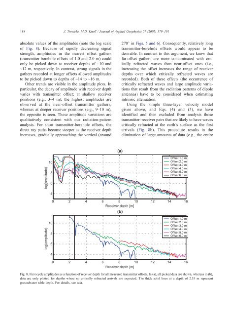
absolute values of the amplitudes (note the log scale<br />
of Fig. 8). Because of rapidly decreasing signal<br />
strength, amplitudes in the nearest offset gathers<br />
(transmitter-borehole offsets of 1.0 and 2.0 m) could<br />
only be picked down to receiver depths of ~10 and<br />
~12 m, respectively. In contrast, strong signals in the<br />
gathers recorded at longer offsets allowed amplitudes<br />
to be picked down to depths of ~14 to ~16 m.<br />
Other trends are visible in the amplitude plots. In<br />
particular, the decay of amplitude with receiver depth<br />
varies with transmitter offset; at shallow receiver<br />
positions (e.g., 3–4 m), the highest amplitudes are<br />
observed at the near-offset transmitter gathers,<br />
whereas at deeper receiver positions (e.g., 9–10 m),<br />
the opposite is seen. These amplitude variations are<br />
qualitatively consistent with our radiation-pattern<br />
analysis. For short transmitter-borehole offsets, the<br />
direct ray paths become steeper as the receiver depth<br />
increases, gradually approaching the vertical (around<br />
2708 in Figs. 5 and 6). Consequently, relatively long<br />
transmitter-borehole offsets would appear to be<br />
desirable. In contrast to this argument, we know that<br />
far-offset gathers are more contaminated with critically<br />
refracted waves than near-offset ones (i.e.,<br />
increasing the offset increases the range of receiver<br />
depths over which critically refracted waves are<br />
recorded). Both of these effects (the occurrence of<br />
critically refracted waves and large amplitude variations<br />
that result from the radiation patterns of dipole<br />
antennas) have to be considered when estimating<br />
intrinsic attenuation.<br />
Using the simple three-layer velocity model<br />
given above, and Eqs. (4) and (5), we have<br />
identified and then excluded from analysis those<br />
transmitter–receiver pairs that are likely to have waves<br />
critically refracted at the earth’s surface as the first<br />
arrivals (Fig. 8b). This procedure results in the<br />
elimination of large amounts of data (e.g., the entire<br />
Fig. 8. First cycle amplitudes as a function of receiver depth for all measured transmitter offsets. In (a), all picked data are shown, whereas in (b),<br />
data are only plotted for depths where no critically refracted arrivals are expected. The thick solid lines at a depth of 2.55 m represent<br />
groundwater table depth. For details, see text.