Vertical radar profiling - CGISS - Boise State University
Vertical radar profiling - CGISS - Boise State University
Vertical radar profiling - CGISS - Boise State University

You also want an ePaper? Increase the reach of your titles
YUMPU automatically turns print PDFs into web optimized ePapers that Google loves.
184<br />
J. Tronicke, M.D. Knoll / Journal of Applied Geophysics 57 (2005) 179–191<br />
model results shown in Figs. 2 and 3 demonstrate that<br />
arrivals critically refracted at the earth’s surface are<br />
likely to occur in shallow VRP surveys for borehole<br />
depths around 10 to 20 m. For locations at which<br />
subsurface velocities are approximately known, our<br />
modeling procedure and results allow investigators to<br />
estimate transmitter-borehole offsets that avoid<br />
unwanted critically refracted arrivals. Furthermore,<br />
such plots help to identify critically refracted waves<br />
during data processing and interpretation.<br />
3. Effects of radiation patterns on recorded<br />
amplitudes<br />
Commercially available geo<strong>radar</strong> surface and borehole<br />
antennas are usually half-wave dipole antennas<br />
with strong directional radiation patterns that depend<br />
on the electrical properties of the surrounding media.<br />
Commonly, a surface dipole antenna is approximated<br />
by a horizontal infinitesimal electric dipole located at<br />
the interface between two homogeneous half-spaces,<br />
one representing air with dielectric permittivity e 0 and<br />
one representing the subsurface with dielectric permittivity<br />
e r e 0 , where e r is the relative permittivity of<br />
the medium (Engheta et al., 1982). The associated<br />
dipole patterns depend strongly on the contrast in<br />
dielectric permittivities between the upper and lower<br />
half-spaces. Although recent studies (e.g., Holliger<br />
and Bergmann, 1998; van der Kruk and Slob, 2000;<br />
Lampe et al., 2003) show that the characteristics of<br />
this model may diverge from those of realistic<br />
geo<strong>radar</strong> surface antennas, the infinitesimal dipole<br />
model describes the main directional dependence of<br />
E-field values associated with a dipole antenna<br />
located on the surface. For a dipole antenna located<br />
within an air-filled borehole, Holliger et al. (2001)<br />
find that the radiation pattern of a vertical infinitesimal<br />
dipole in full-space is a valid approximation.<br />
When the borehole contains water, the radiation<br />
pattern is distorted, such that this approximation<br />
may be inadequate (Holliger et al., 2001).<br />
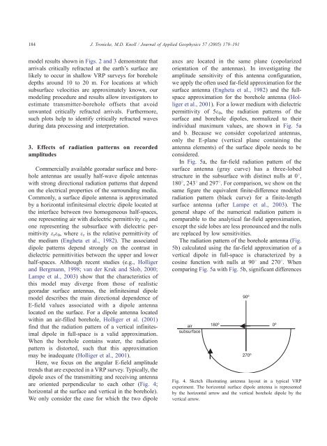
Here, we focus on the angular E-field amplitude<br />
trends that are expected in a VRP survey. Typically, the<br />
dipole axes of the transmitting and receiving antenna<br />
are oriented perpendicular to each other (Fig. 4;<br />
horizontal at the surface and vertical in the borehole).<br />
We only consider the case for which the two dipole<br />
axes are located in the same plane (copolarized<br />
orientation of the antennas). In investigating the<br />
amplitude sensitivity of this antenna configuration,<br />
we apply the often used far-field approximation for the<br />
surface antenna (Engheta et al., 1982) and the fullspace<br />
approximation for the borehole antenna (Holliger<br />
et al., 2001). For a lower medium with dielectric<br />
permittivity of 5e 0 , the radiation patterns of the<br />
surface and borehole dipoles, normalized to their<br />
individual maximum values, are shown in Fig. 5a<br />
and b. Because we consider copolarized antennas,<br />
only the E-plane (vertical plane containing the<br />
antenna elements) of the surface dipole needs to be<br />
considered.<br />
In Fig. 5a, the far-field radiation pattern of the<br />
surface antenna (gray curve) has a three-lobed<br />
structure in the subsurface with distinct nulls at 08,<br />
1808, 2438 and 2978. For comparison, we show on the<br />
same figure the equivalent finite-difference modeled<br />
radiation pattern (black curve) for a finite-length<br />
surface antenna (after Lampe et al., 2003). The<br />
general shape of the numerical radiation pattern is<br />
comparable to the analytical far-field approximation,<br />
except the side lobes are less pronounced and the nulls<br />
are replaced by low sensitivities.<br />
The radiation pattern of the borehole antenna (Fig.<br />
5b) calculated using the far-field approximation of a<br />
vertical dipole in full-space is characterized by a<br />
cosine function with nulls at 908 and 2708. When<br />
comparing Fig. 5a with Fig. 5b, significant differences<br />
Fig. 4. Sketch illustrating antenna layout in a typical VRP<br />
experiment. The horizontal surface dipole antenna is represented<br />
by the horizontal arrow and the vertical borehole dipole by the<br />
vertical arrow.