Vertical radar profiling - CGISS - Boise State University
Vertical radar profiling - CGISS - Boise State University
Vertical radar profiling - CGISS - Boise State University

You also want an ePaper? Increase the reach of your titles
YUMPU automatically turns print PDFs into web optimized ePapers that Google loves.
186<br />
J. Tronicke, M.D. Knoll / Journal of Applied Geophysics 57 (2005) 179–191<br />
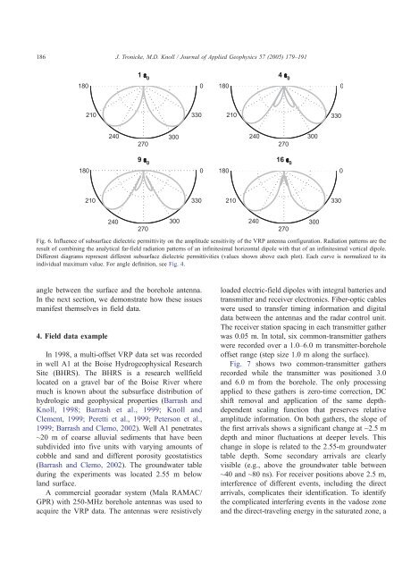
Fig. 6. Influence of subsurface dielectric permittivity on the amplitude sensitivity of the VRP antenna configuration. Radiation patterns are the<br />
result of combining the analytical far-field radiation patterns of an infinitesimal horizontal dipole with that of an infinitesimal vertical dipole.<br />
Different diagrams represent different subsurface dielectric permittivities (values shown above each plot). Each curve is normalized to its<br />
individual maximum value. For angle definition, see Fig. 4.<br />
angle between the surface and the borehole antenna.<br />
In the next section, we demonstrate how these issues<br />
manifest themselves in field data.<br />
4. Field data example<br />
In 1998, a multi-offset VRP data set was recorded<br />
in well A1 at the <strong>Boise</strong> Hydrogeophysical Research<br />
Site (BHRS). The BHRS is a research wellfield<br />
located on a gravel bar of the <strong>Boise</strong> River where<br />
much is known about the subsurface distribution of<br />
hydrologic and geophysical properties (Barrash and<br />
Knoll, 1998; Barrash et al., 1999; Knoll and<br />
Clement, 1999; Peretti et al., 1999; Peterson et al.,<br />
1999; Barrash and Clemo, 2002). Well A1 penetrates<br />
~20 m of coarse alluvial sediments that have been<br />
subdivided into five units with varying amounts of<br />
cobble and sand and different porosity geostatistics<br />
(Barrash and Clemo, 2002). The groundwater table<br />
during the experiments was located 2.55 m below<br />
land surface.<br />
A commercial geo<strong>radar</strong> system (Mala RAMAC/<br />
GPR) with 250-MHz borehole antennas was used to<br />
acquire the VRP data. The antennas were resistively<br />
loaded electric-field dipoles with integral batteries and<br />
transmitter and receiver electronics. Fiber-optic cables<br />
were used to transfer timing information and digital<br />
data between the antennas and the <strong>radar</strong> control unit.<br />
The receiver station spacing in each transmitter gather<br />
was 0.05 m. In total, six common-transmitter gathers<br />
were recorded over a 1.0–6.0 m transmitter-borehole<br />
offset range (step size 1.0 m along the surface).<br />
Fig. 7 shows two common-transmitter gathers<br />
recorded while the transmitter was positioned 3.0<br />
and 6.0 m from the borehole. The only processing<br />
applied to these gathers is zero-time correction, DC<br />
shift removal and application of the same depthdependent<br />
scaling function that preserves relative<br />
amplitude information. On both gathers, the slope of<br />
the first arrivals shows a significant change at ~2.5 m<br />
depth and minor fluctuations at deeper levels. This<br />
change in slope is related to the 2.55-m groundwater<br />
table depth. Some secondary arrivals are clearly<br />
visible (e.g., above the groundwater table between<br />
~40 and ~80 ns). For receiver positions above 2.5 m,<br />
interference of different events, including the direct<br />
arrivals, complicates their identification. To identify<br />
the complicated interfering events in the vadose zone<br />
and the direct-traveling energy in the saturated zone, a