Brooks Instrument 1350E and 1355E User Manual - The Meter and ...
Brooks Instrument 1350E and 1355E User Manual - The Meter and ...
Brooks Instrument 1350E and 1355E User Manual - The Meter and ...

Create successful ePaper yourself
Turn your PDF publications into a flip-book with our unique Google optimized e-Paper software.
Installation <strong>and</strong> Operation <strong>Manual</strong><br />
X-VA-<strong>1350E</strong>-eng<br />
Part Number: 541B082AAG<br />
April, 2009<br />
Models <strong>1350E</strong> <strong>and</strong> <strong>1355E</strong><br />
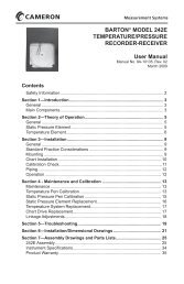
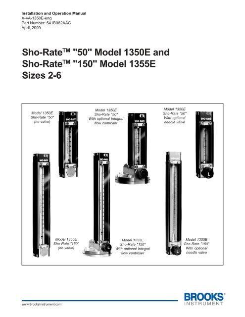
Sho-Rate TM "50" Model <strong>1350E</strong> <strong>and</strong><br />
Sho-Rate TM "150" Model <strong>1355E</strong><br />
Sizes 2-6<br />
Model <strong>1350E</strong><br />
Sho-Rate "50"<br />
(no valve)<br />
Model <strong>1350E</strong><br />
Sho-Rate "50"<br />
With optional Integral<br />
flow controller<br />
Model <strong>1350E</strong><br />
Sho-Rate "50"<br />
With optional<br />
needle valve<br />
Model <strong>1355E</strong><br />
Sho-Rate "150"<br />
(no valve)<br />
Model <strong>1355E</strong><br />
Sho-Rate "150"<br />
With optional Integral<br />
flow controller<br />
Model <strong>1355E</strong><br />
Sho-Rate "150"<br />
With optional<br />
needle valve
Models <strong>1350E</strong> <strong>and</strong> <strong>1355E</strong><br />
Installation <strong>and</strong> Operation <strong>Manual</strong><br />
X-VA-<strong>1350E</strong>-eng<br />
Part Number: 541B082AAG<br />
April, 2009<br />
Essential Instructions<br />
Read this page before proceeding!<br />
<strong>Brooks</strong> <strong>Instrument</strong> designs, manufactures <strong>and</strong> tests its products to meet many national <strong>and</strong> international st<strong>and</strong>ards. Because<br />
these instruments are sophisticated technical products, you must properly install, use <strong>and</strong> maintain them to ensure they<br />
continue to operate within their normal specifications. <strong>The</strong> following instructions must be adhered to <strong>and</strong> integrated into your<br />
safety program when installing, using <strong>and</strong> maintaining <strong>Brooks</strong> Products.<br />
• Read all instructions prior to installing, operating <strong>and</strong> servicing the product. If this instruction manual is not the correct<br />
manual, please see back cover for local sales office contact information. Save this instruction manual for future reference.<br />
• If you do not underst<strong>and</strong> any of the instructions, contact your <strong>Brooks</strong> <strong>Instrument</strong> representative for clarification.<br />
• Follow all warnings, cautions <strong>and</strong> instructions marked on <strong>and</strong> supplied with the product.<br />
• Inform <strong>and</strong> educate your personnel in the proper installation, operation <strong>and</strong> maintenance of the product.<br />
• Install your equipment as specified in the installation instructions of the appropriate instruction manual <strong>and</strong> per applicable<br />
local <strong>and</strong> national codes. Connect all products to the proper electrical <strong>and</strong> pressure sources.<br />
• To ensure proper performance, use qualified personnel to install, operate, update, program <strong>and</strong> maintain the product.<br />
• When replacement parts are required, ensure that qualified people use replacement parts specified by <strong>Brooks</strong> <strong>Instrument</strong>.<br />
Unauthorized parts <strong>and</strong> procedures can affect the product's performance <strong>and</strong> place the safe operation of your process at<br />
risk. Look-alike substitutions may result in fire, electrical hazards or improper operation.<br />
• Ensure that all equipment doors are closed <strong>and</strong> protective covers are in place, except when maintenance is being<br />
performed by qualified persons, to prevent electrical shock <strong>and</strong> personal injury.<br />
Pressure Equipment Directive (PED)<br />
All pressure equipment with an internal pressure greater than 0.5 bar (g) <strong>and</strong> a size larger than 25mm or 1" (inch) falls under the<br />
Pressure Equipment Directive (PED). <strong>The</strong> Directive is applicable within the European Economic Area (EU plus Norway, Icel<strong>and</strong><br />
<strong>and</strong> Liechtenstein). Pressure equipment can be traded freely within this area once the PED has been complied with.<br />
• Section 1 of this manual contains important safety <strong>and</strong> operating instructions related to the PED directive.<br />
• <strong>Meter</strong>s described in this manual are in compliance with EN directive 97/23/EC module H Conformity Assessment.<br />
• All <strong>Brooks</strong> <strong>Instrument</strong> Flowmeters fall under fluid group 1.<br />
• <strong>Meter</strong>s larger than 25mm or 1" (inch) are in compliance with category I, II, III of PED.<br />
• <strong>Meter</strong>s of 25mm or 1" (inch) or smaller are Sound Engineering Practice (SEP).
Installation <strong>and</strong> Operation <strong>Manual</strong><br />
X-VA-<strong>1350E</strong>-eng<br />
Part Number: 541B082AAG<br />
April, 2009<br />
Models <strong>1350E</strong> <strong>and</strong> <strong>1355E</strong><br />
Dear Customer,<br />
We appreciate this opportunity to service your flow measurement <strong>and</strong> control requirements with a <strong>Brooks</strong><br />
<strong>Instrument</strong> device. Every day, flow customers all over the world turn to <strong>Brooks</strong> <strong>Instrument</strong> for solutions to their<br />
gas <strong>and</strong> liquid low-flow applications. <strong>Brooks</strong> provides an array of flow measurement <strong>and</strong> control products for<br />
various industries from biopharmaceuticals, oil <strong>and</strong> gas, fuel cell research <strong>and</strong> chemicals, to medical devices,<br />
analytical instrumentation, semiconductor manufacturing, <strong>and</strong> more.<br />
<strong>The</strong> <strong>Brooks</strong> product you have just received is of the highest quality available, offering superior performance,<br />
reliability <strong>and</strong> value to the user. It is designed with the ever changing process conditions, accuracy requirements<br />
<strong>and</strong> hostile process environments in mind to provide you with a lifetime of dependable service.<br />
We recommend that you read this manual in its entirety. Should you require any additional information concerning<br />
<strong>Brooks</strong> products <strong>and</strong> services, please contact your local <strong>Brooks</strong> Sales <strong>and</strong> Service Office listed on the back cover<br />
of this manual or visit www.<strong>Brooks</strong><strong>Instrument</strong>.com<br />
Yours sincerely,<br />
<strong>Brooks</strong> <strong>Instrument</strong>
Models <strong>1350E</strong> <strong>and</strong> <strong>1355E</strong><br />
Installation <strong>and</strong> Operation <strong>Manual</strong><br />
X-VA-<strong>1350E</strong>-eng<br />
Part Number: 541B082AAG<br />
April, 2009<br />
THIS PAGE WAS<br />
INTENTIONALLY<br />
LEFT BLANK
Installation <strong>and</strong> Operation <strong>Manual</strong><br />
X-VA-<strong>1350E</strong>-eng<br />
Part Number: 541B082AAG<br />
April, 2009<br />
Contents<br />
Models <strong>1350E</strong> <strong>and</strong> <strong>1355E</strong><br />
Section 1 Introduction<br />
Paragraph<br />
Page<br />
Number<br />
Number<br />
1-1 Description................................................................................................................................................. 1-1<br />
1-2 Specifications............................................................................................................................................. 1-1<br />
1-3 Optional Equipment ................................................................................................................................... 1-5<br />
Section 2 Installation<br />
Paragraph<br />
Page<br />
Number<br />
Number<br />
2-1 Receipt of Equipment ................................................................................................................................ 2-1<br />
2-2 Unpacking.................................................................................................................................................. 2-1<br />
2-3 Return Shipment........................................................................................................................................ 2-2<br />
2-4 Recommended Storage Practice ............................................................................................................... 2-2<br />
2-5 Installation ................................................................................................................................................. 2-3<br />
Section 3 Operation<br />
Paragraph<br />
Page<br />
Number<br />
Number<br />
3-1 Operation ................................................................................................................................................... 3-1<br />
Section 4 Maintenance<br />
Paragraph<br />
Page<br />
Number<br />
Number<br />
4-1 Disassembly & Cleaning ............................................................................................................................ 4-1<br />
4-2 Reassembly procedure .............................................................................................................................. 4-1<br />
Section 5 Parts List<br />
Paragraph<br />
Page<br />
Number<br />
Number<br />
5-1 General ...................................................................................................................................................... 5-1<br />
Figures<br />
Figure<br />
Page<br />
Number<br />
Number<br />
2-1 Typical Flowmeter Installation .................................................................................................................... 2-3<br />
2-2 Dimensions - Sho-Rate <strong>1350E</strong>................................................................................................................... 2-4<br />
2-3 Dimensions - Sho-Rate <strong>1350E</strong> <strong>and</strong> <strong>1355E</strong> with Integral Controller............................................................ 2-5<br />
2-4 Dimensions - Sho-Rate <strong>1355E</strong>................................................................................................................... 2-6<br />
5-1 Parts Drawing Sho-Rate Models <strong>1350E</strong> <strong>and</strong> <strong>1355E</strong> .................................................................................. 5-2<br />
Tables<br />
Table<br />
Page<br />
Number<br />
Number<br />
1-1 Capacities for Sho-Rate Model <strong>1350E</strong> Rib Guided Tubes, Spherical Floats ............................................. 1-3<br />
1-2 Capacities for Sho-Rate Model <strong>1350E</strong> Plain Tapered Tube, Spherical Floats ........................................... 1-3<br />
1-3 Tube <strong>and</strong> Float Code, Detachable Scale Option, 1st Digit......................................................................... 1-4<br />
1-4 Tube <strong>and</strong> Float Code, Detachable Scale Option, 2nd & 3rd Digits ............................................................ 1-4<br />
1-5 Capacities for Sho-Rate Model <strong>1355E</strong> Rib Guided Tubes, Spherical Floats ............................................. 1-4<br />
5-1 Parts List - Sho-Rate Models <strong>1350E</strong> <strong>and</strong> <strong>1355E</strong> ....................................................................................... 5-3<br />
i
Contents<br />
Models <strong>1350E</strong> <strong>and</strong> <strong>1355E</strong><br />
Installation <strong>and</strong> Operation <strong>Manual</strong><br />
X-VA-<strong>1350E</strong>-eng<br />
Part Number: 541B082AAG<br />
April, 2009<br />
THIS PAGE WAS<br />
INTENTIONALLY<br />
LEFT BLANK<br />
ii
Installation <strong>and</strong> Operation <strong>Manual</strong><br />
X-VA-<strong>1350E</strong>-eng<br />
Part Number: 541B082AAG<br />
April, 2009<br />
Section 1 Introduction<br />
Models <strong>1350E</strong> <strong>and</strong> <strong>1355E</strong><br />
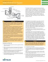
1-1 Description<br />
<strong>The</strong> Sho-Rate Flowmeters are variable area, glass tube, flow rate<br />
indicating meters. <strong>The</strong> basic elements are a tapered glass metering tube<br />
<strong>and</strong> a metering float. Features include quick <strong>and</strong> simple removal or<br />
installation of the tube <strong>and</strong> float while the meter remains in the process<br />
piping.<br />
1-2 Specifications<br />
Capacities<br />
1350 Series: Refer to Tables 1-1 or 1-2, or 1-3 <strong>and</strong> 1-4<br />
1355 Series: Refer to Tables 1-3 <strong>and</strong> 1-4, or 1-5<br />
Accuracy<br />
1350 Series St<strong>and</strong>ard: Accuracy of ±10% of full scale from 100% to 10% of<br />
scale reading<br />
1355 Series St<strong>and</strong>ard: ±5% of full scale from 100% to 10% of scale<br />
reading<br />
Repeatability<br />
0.5% full scale<br />
Rangeability<br />
10 to 1<br />
Pressure<br />
200 psig at temperatures up to 250°F<br />
Pressure Drop<br />
Inquire at factory<br />
Flow <strong>Meter</strong> Assembly<br />
Pressure Equipment Directive (97/23/EC)<br />
Note: Equipment falls under Sound Engineering Practice (SEP) according<br />
to the<br />
directive.<br />
1-1
Section 1 Introduction<br />
Models <strong>1350E</strong> <strong>and</strong> <strong>1355E</strong><br />
Installation <strong>and</strong> Operation <strong>Manual</strong><br />
X-VA-<strong>1350E</strong>-eng<br />
Part Number: 541B082AAG<br />
April, 2009<br />
Scales<br />
1350 Series:<br />
Length: 65 mm, nominal<br />
Graduations: St<strong>and</strong>ard: 0-65mm, or 0-100 linear reference scale with air or<br />
water calibration table.<br />
1355 Series:<br />
Length: 150mm, nominal<br />
Graduations: St<strong>and</strong>ard: 0-150 mm, or 0-100 linear reference scale with air<br />
or water calibration table. Optional: for either 65 mm or 150 mm direct<br />
reading scale, ceramic ink fused on glass tube or metal scale plate<br />
mounted beside tube<br />
Type: St<strong>and</strong>ard: Ceramic ink fused on meter tube with contrasting yellow<br />
background<br />
Materials of Construction<br />
<strong>Meter</strong>ing Tubes: Borosilicate glass<br />
Floats: Glass, 316 stainless steel, sapphire,<br />
Carboloy ® , tantalum<br />
Structural Members:<br />
End fittings: Chrome plated brass, black anodized aluminum, 316<br />
stainless steel<br />
Side Plates:<br />
St<strong>and</strong>ard: Black anodized aluminum<br />
Optional: 316 stainless steel<br />
Window: Clear polycarbonate; Back Window: Milk white polycarbonate<br />
Float Stops:<br />
St<strong>and</strong>ard: Teflon ®<br />
Optional: 316 Stainless Steel<br />
Tube Packing:<br />
St<strong>and</strong>ard: Buna-N (Brass <strong>and</strong> aluminum meters), Viton-A ®<br />
fluoroelastomers (316 stainless steel meters)<br />
Optional: Teflon, EPM (also known as EPR)<br />
O-rings:<br />
St<strong>and</strong>ard: Buna-N (Brass <strong>and</strong> aluminum meters), Viton-A fluoroelastomers<br />
(316 stainless steel meters)<br />
Optional: Teflon (not available with needle valves), EPM, Kalrez ®<br />
Connections<br />
St<strong>and</strong>ard: Horizontal female 1/8" NPT threaded adapters with locknuts for<br />
front of panel mounting<br />
Multi-tube meters: Individual 1/8" NPT horizontal inlet <strong>and</strong> outlet; Manifold<br />
connection 1/8" NPT on inlet with individual outlet or manifold outlet with<br />
individual inlet connections.<br />
Dimensions<br />
Refer to Figures 2-2 <strong>and</strong> 2-3<br />
1-2
Installation <strong>and</strong> Operation <strong>Manual</strong><br />
X-VA-<strong>1350E</strong>-eng<br />
Part Number: 541B082AAG<br />
April, 2009<br />
Section 1 Introduction<br />
Models <strong>1350E</strong> <strong>and</strong> <strong>1355E</strong><br />
Table 1-1 Capacities for Sho-Rate Model <strong>1350E</strong> Rib Guided Tubes, Spherical Floats<br />
RIBBED TUBES, SPHERICAL FLOATS<br />
M ETER TUBE FLOAT MAXIM UM FLOW RATE<br />
SIZE NO. MATERIAL WATER AIR*<br />
GPH CODE LPH CODE SCFH CODE NLPH CODE<br />
GLASS 0.011 JB6 0.042 JB9 0.13 JB7 3.4 JB8<br />
SAPPHIRE 0.022 JC4 0.085 JC2 0.18 JC3 5.0 JC1<br />
R-2-65-A STN. STL. 0.046 JC8 0.18 JC5 0.34 JC7 9.0 JC6<br />
CARBOLOY 0.10 JB4 0.38 JB5 0.65 JB2 17.0 JB3<br />
TANTALUM 0.11 JD2 0.42 JC9 0.70 JD1 19.0 JD3<br />
GLASS 0.013 KB8 0.048 KB2 0.15 KB7 4.0 KB9<br />
SAPPHIRE 0.026 KC1 0.10 KD3 0.22 KC2 5.5 KC3<br />
R-2-65-B STN. STL. 0.06 KC5 0.22 KC6 0.42 KC7 11.0 KC8<br />
CARBOLOY 0.12 KB4 0.48 KB5 0.80 KB3 22.0 KB6<br />
TANTALUM 0.13 KD2 0.50 KD5 0.85 KD4 22.0 KD1<br />
2 GLASS 0.11 LB9 0.42 LB7 0.95 LB6 24.0 LB8<br />
SAPPHIRE 0.15 LC1 0.6 LC2 1.3 LC3 34.0 LC4<br />
R-2-65-C STN. STL. 0.38 LC7 1.4 LC8 2.0 LC9 50.0 LC6<br />
CARBOLOY 0.65 LB3 2.4 LB2 3.0 LB4 80.0 LB5<br />
TANTALUM 0.65 LD1 2.6 LD2 3.2 LD3 85.0 LD4<br />
GLASS 0.65 M B9 2.4 MB7 3.8 MB8 100 M C1<br />
SAPPHIRE 0.95 MC2 3.6 MC3 5.0 MC4 130 MC5<br />
R-2-65-D STN. STL. 1.60 MC7 6.0 MD1 7.5 MC6 200 MC8<br />
CARBOLOY 2.40 MB5 9.0 MB2 11.0 MB3 280 MB4<br />
TANTALUM 2.60 MD5 10.0 MD6 12.0 MD2 300 MD4<br />
GLASS 2.40 NB8 8.5 NB7 13.0 NC1 340 NB9<br />
SAPPHIRE 3.40 NC4 13.0 NC3 17.0 NC6 460 NC5<br />
R-6-65-A STN. STL. 5.50 ND1 20.0 ND3 26.0 NC9 650 ND2<br />
CARBOLOY 8.50 NB2 32.0 NB3 36.0 NB5 950 NB6<br />
TANTALUM 9.0 ND6 34.0 ND5 38.0 ND7 1000 ND4<br />
6 GLASS 8.0 PB9 30.0 PB8 44.0 PC1 1100 PB7<br />
SAPPHIRE 12.0 PC5 44.0 PC3 60.0 PC4 1500 PC2<br />
R-6-65-B STN. STL. 19.0 PD1 70.0 PC9 85.0 PC8 2200 PC6<br />
CARBOLOY 28.0 PB3 100 PB2 130 PB6 3400 PB4<br />
TANTALUM 30.0 PD7 110 PD6 140 PD5 3600 PD4<br />
* FLOW RATES GIVEN ARE MAXIMUM VALUES. AIR FLOWS ARE AT 14.7 PSIA AND 70 DEGREES F.<br />
Table 1-2 Capacities for Sho-Rate Model <strong>1350E</strong> Plain Tapered Tubes, Spherical Floats<br />
PLAIN TAPER TUBES, SPHERICAL FLOATS<br />
SCFH Press. Drop ** GPH Press. Drop **<br />
TUBE AND FLOAT AIR* Inches W.C. CODE TUBE AND FLOAT WATER Inches W.C. CODE<br />
1-65A GLASS 1.2 1.0 AB4 1-65C GLASS 0.14 1.8 AB5<br />
2-65A GLASS 2.0 2.2 BA7 2-65C STN. STL. 0.5 4.0 DA5<br />
2-65B STN. STL 5.0 10.8 CA4 2-65D STN. STL. 1.0 19.5 CA8<br />
3-65A GLASS 6.0 12.4 EB4 3-65C GLASS 0.7 22.3 EB9<br />
3-65B STN. STL 10 10.1 EB8 3-65D STN. STL 1.6 18.3 EC1<br />
4-65A GLASS 12 10.4 FC3 4-65C GLASS 2.0 18.7 FD3<br />
4-65B STN. STL 18 25 FC8 4-65D STN. STL 4.0 45 FD6<br />
5-65A GLASS 45 60 GB6 5-65C GLASS 9.0 109 GC4<br />
5-65B STN. STL 80 214 GC1 5-65D STN. STL 17 385 GC5<br />
6-65A GLASS 55 73 HB8 6-65C GLASS 11 132 HC7<br />
6-65B STN. STL 90 292 HC5 6-65D STN. STL 20 525 HD1<br />
6-65E CARBOLOY 120 400 HD3 6-65F CARBOLOY 30 890 HD4<br />
* FLOW RATES ARE MAXIMUM VALUES. AIR FLOWS ARE AT 14.7 PSIA AND 70 DEGREES F<br />
** PRESSURE DROPS ARE APPROXIMATE<br />
1-3
Section 1 Introduction<br />
Models <strong>1350E</strong> <strong>and</strong> <strong>1355E</strong><br />
Installation <strong>and</strong> Operation <strong>Manual</strong><br />
X-VA-<strong>1350E</strong>-eng<br />
Part Number: 541B082AAG<br />
April, 2009<br />
Table 1-3 Tube <strong>and</strong> Float Code,<br />
Detachable Scale Option, 1st Digit<br />
CODE MODEL 1350 TUBE MODEL 1355 TUBE<br />
A 1-65 R-2-15-A<br />
B 2-65A R-2-15-AA<br />
C 2-65B & D R-2-15-AAA<br />
D 2-65C R-2-15-B<br />
E 3-65 R-2-15-C<br />
F 4-65 R-2-15-D<br />
G 5-65 R-6-15-A<br />
H 6-65 R-6-15-B<br />
J<br />
R-2-65-A<br />
K<br />
R-2-65-B<br />
L<br />
R-2-65-C<br />
M<br />
R-2-65-D<br />
N<br />
R-6-65-A<br />
P<br />
R-6-65-B<br />
Y NO TUBE NO TUBE<br />
Table 1-4 Tube <strong>and</strong> Float Code,<br />
Detachable Scale Option, 2nd & 3rd Digits<br />
DETACHABLE SCALE INSCRIPTION<br />
METER FLOAT SPECIAL SPECIAL<br />
ACCURACY MATERIAL 0-100 SINGLE DUAL BLANK<br />
MM LINEAR SCALE SCALE SCALE<br />
STANDARD GLASS 1A 1N 2A 2N 3A<br />
(1350-10%) STN. STL. 1B 1P 2B 2P 3B<br />
(1355- 5%) SAPPHIRE 1C 1Q 2C 2Q 3C<br />
CARBOLOY 1D 1R 2D 2R 3D<br />
TANTALUM 1E 1S 2E 2S 3E<br />
*ALUMINUM 1F 1T 2F 2T 3F<br />
CALIBRATED GLASS 1G 1U 2G 2U<br />
(1350-5%) STN. STL. 1H 1V 2H 2V<br />
(1355-2%) SAPPHIRE 1J 1W 2J 2W<br />
CARBOLOY 1K 1X 2K 2X<br />
TANTALUM 1L 1Y 2L 2Y<br />
*ALUMINUM 1M 1Z 2M 2Z<br />
N/A NONE 9A 9B 9C<br />
Table 1-5 Capacities for Sho-Rate Model <strong>1355E</strong> Rib Guided Tubes, Spherical Floats<br />
*ALUMINUM SPOOL FLOAT FOR 15 CC/MIN AIR AVAILABLE ONLY WITH R-2-15-AAA<br />
CAPACITIES (RIB GUIDE TUBES, SPHERICAL FLOATS) - FOR USE WITH 1355 SERIES ONLY<br />
M AXIMUM FLOW RATE * MODEL CODE - SCALE ON TUBE<br />
METER<br />
WATER<br />
SIZE TUBE NO. FLOAT MATERIAL (CC/MIN.) AIR 0-150 MM 10-100% 0-100 LINEAR<br />
GLASS 0.524 47.1 SCC/M CA6 CA1<br />
SAPPHIRE 1.02 73.3 SCC/M CA8 CA3<br />
R-2-15-AAA STN. STL. 2.42 140 SCC/M CA7 CA2<br />
CARBOLOY 4.77 238 SCC/M CA9 CA4<br />
TANTALUM 5.31 260 SCC/M CB1 CA5<br />
GLASS 0.964 83.8 SCC/M BA6 BA1<br />
SAPPHIRE 1.86 128 SCC/M BA8 BA3<br />
R-2-15-AA STN. STL. 4.34 245 SCC/M BA7 BA2<br />
CARBOLOY 8.37 416 SCC/M BA9 BA4<br />
TANTALUM 9.30 454 SCC/M BB1 BA5<br />
GLASS 5.58 361 SCC/M FA6 FA1<br />
SAPPHIRE 10.2 491 SCC/M FA8 FA3<br />
2 R-2-15-D STN. STL. 19.8 790 SCC/M FA7 FA2<br />
CARBOLOY 31.9 1170 SCC/M FA9 FA4<br />
TANTALUM 34.4 1250 SCC/M FB1 LIQ. GAS FA5<br />
GLASS 16.1 0.790 SLPM AA6 AB7 AC3 AA1<br />
SAPPHIRE 25.2 1.04 SLPM AA8 AB9 AC4 AA3<br />
R-2-15-A STN. STL. 44.2 1.60 SLPM AA7 AB8 AC6 AA2<br />
CARBOLOY 67.7 2.32 SLPM AA9 AC1 AC5 AA4<br />
TANTALUM 72.5 2.46 SLPM AB1 AC2 AC7 AA5<br />
GLASS 50.6 2.25 SLPM DA6 DB2 DA1<br />
SAPPHIRE 76.2 2.92 SLPM DA8 DB4 DA3<br />
R-2-15-B STN. STL. 127 4.42 SLPM DA7 DB3 DA2<br />
CARBOLOY 189 6.35 SLPM DA9 DB5 DA4<br />
TANTALUM 202 6.74 SLPM DB1 DB6 DA5<br />
GLASS 81.1 3.69 SLPM EA6 EB2 EA1<br />
SAPPHIRE 123 4.81 SLPM EA8 EB4 EA3<br />
R-2-15-C STN. STL. 208 7.23 SLPM EA7 EB3 EA2<br />
CARBOLOY 312 10.1 SLPM EA9 EB5 EA4<br />
TANTALUM 333 10.6 SLPM EB1 EB6 EA5<br />
GLASS 191 8.26 SLPM GA6 GB2 GA1<br />
SAPPHIRE 284 10.6 SLPM GA8 GB4 GA3<br />
R-6-15-A STN. STL. 468 15.7 SLPM GA7 GB3 GA2<br />
CARBOLOY 690 22.0 SLPM GA9 GB5 GA4<br />
6 TANTALUM 735 23.3 SLPM GB1 GB6 GA5<br />
GLASS 548 22.6 SLPM HA6 HB2 HA1<br />
SAPPHIRE 809 28.6 SLPM HA8 HB4 HA3<br />
R-6-15-B STN. STL. 1290 41.6 SLPM HA7 HB3 HA2<br />
CARBOLOY 1850 58.1 SLPM HA9 HB5 HA4<br />
TANTALUM 1960 61.4 SLPM HB1 HB6 HA5<br />
NOTE: ALL AIR FLOWS ARE AT 14.7 PSIA AND 70 DEGREES F.<br />
* FLOW RATES SHOWN ARE M AXIMUM CAPACITIES. DIRECT READ SCALES MAY END AT SLIGHTLY DIFFERENT<br />
MAXIMUM FLOWS.<br />
1-4
Installation <strong>and</strong> Operation <strong>Manual</strong><br />
X-VA-<strong>1350E</strong>-eng<br />
Part Number: 541B082AAG<br />
April, 2009<br />
Section 1 Introduction<br />
Models <strong>1350E</strong> <strong>and</strong> <strong>1355E</strong><br />
1-3 Optional Equipment<br />
St<strong>and</strong>ard Needle Valve<br />
<strong>The</strong> st<strong>and</strong>ard needle valve can be supplied integrally mounted to the inlet<br />
or outlet of the instrument. For more details on the needle valve go to our<br />
website: <strong>Brooks</strong><strong>Instrument</strong>.com, select Documentation, Precision Valves<br />
& Flow Controllers, select <strong>Brooks</strong>-Line IV, CART, 8503 or 8504 valves.<br />
Flow Contollers<br />
Flow controllers can be supplied integrally mounted to the inlet or outlet of<br />
the instrument. For the flow controller's complete instruction manual go to<br />
our website: <strong>Brooks</strong><strong>Instrument</strong>.com, select Documentation, Precision<br />
Valves & Flow Controllers, select FC8800, or FC8900.<br />
1-5
Section 1 Introduction<br />
Models <strong>1350E</strong> <strong>and</strong> <strong>1355E</strong><br />
Installation <strong>and</strong> Operation <strong>Manual</strong><br />
X-VA-<strong>1350E</strong>-eng<br />
Part Number: 541B082AAG<br />
April, 2009<br />
THIS PAGE WAS<br />
INTENTIONALLY<br />
LEFT BLANK<br />
1-6
Installation <strong>and</strong> Operation <strong>Manual</strong><br />
X-VA-<strong>1350E</strong>-eng<br />
Part Number: 541B082AAG<br />
April, 2009<br />
Section 2 Installation<br />
Models <strong>1350E</strong> <strong>and</strong> <strong>1355E</strong><br />
2-1 Receipt of Equipment<br />
When the equipment is received, the outside of the packing case should be<br />
checked for any damage incurred during shipment. If the packing case is<br />
damaged, the local carrier should be notified at once regarding his liability.<br />
Remove the envelope containing the shipping list. Carefully remove the<br />
equipment from the packing case <strong>and</strong> inspect for any damaged or missing<br />
parts.<br />
In the event that the meter is damaged during shipment, the Product<br />
Service Department, <strong>Brooks</strong> <strong>Instrument</strong>,LLC, Hatfield, PA 19440 should be<br />
contacted to obtain a return shipment form.<br />
<strong>Brooks</strong> <strong>Instrument</strong><br />
407 W. Vine Street<br />
P.O. Box 903<br />
Hatfield, PA 19440 USA<br />
Toll Free (888) 554 FLOW (3569)<br />
Tel (215) 362 3700<br />
Fax (215) 362 3745<br />
E-mail: <strong>Brooks</strong>Am@<strong>Brooks</strong><strong>Instrument</strong>.com<br />
www.<strong>Brooks</strong><strong>Instrument</strong>.com<br />
<strong>Brooks</strong> <strong>Instrument</strong><br />
<strong>Brooks</strong> <strong>Instrument</strong><br />
Neonstraat 3<br />
1-4-4 Kitasuna Koto-Ku<br />
6718 WX Ede, Netherl<strong>and</strong>s Tokyo, 136-0073 Japan<br />
P.O. Box 428 Tel +81 (0) 3 5633 7100<br />
6710 BK Ede, Netherl<strong>and</strong>s Fax +81 (0) 3 5633 7101<br />
Tel +31 (0) 318 549 300<br />
Email: <strong>Brooks</strong>As@<strong>Brooks</strong><strong>Instrument</strong>.com<br />
Fax +31 (0) 318 549 309<br />
E-mail: <strong>Brooks</strong>Eu@<strong>Brooks</strong><strong>Instrument</strong>.com<br />
2-2 Unpacking<br />
Carefully unpack the meter <strong>and</strong> inspect it for any damage that may have<br />
occurred during shipment. <strong>The</strong> flowmeters are shipped completely<br />
assembled <strong>and</strong> tested. It should not be necessary to tighten or adjust any<br />
of the parts when it is received.<br />
2-1
Section 2 Installation<br />
Models <strong>1350E</strong> <strong>and</strong> <strong>1355E</strong><br />
Installation <strong>and</strong> Operation <strong>Manual</strong><br />
X-VA-<strong>1350E</strong>-eng<br />
Part Number: 541B082AAG<br />
April, 2009<br />
2-3 Return Shipment<br />
Do not return any assembly or part without a Return Materials Report. <strong>The</strong><br />
Return Materials Report is available from all District Sales Offices <strong>and</strong> the<br />
Product Service Department, Hatfield, PA 19440. Information describing<br />
the problem, corrective action, if any, <strong>and</strong> the work to be accomplished at<br />
the factory must be included.<br />
<strong>Brooks</strong> <strong>Instrument</strong><br />
407 W. Vine Street<br />
P.O. Box 903<br />
Hatfield, PA 19440 USA<br />
Toll Free (888) 554 FLOW (3569)<br />
Tel (215) 362 3700<br />
Fax (215) 362 3745<br />
E-mail: <strong>Brooks</strong>Am@<strong>Brooks</strong><strong>Instrument</strong>.com<br />
www.<strong>Brooks</strong><strong>Instrument</strong>.com<br />
<strong>Brooks</strong> <strong>Instrument</strong><br />
<strong>Brooks</strong> <strong>Instrument</strong><br />
Neonstraat 3<br />
1-4-4 Kitasuna Koto-Ku<br />
6718 WX Ede, Netherl<strong>and</strong>s Tokyo, 136-0073 Japan<br />
P.O. Box 428 Tel +81 (0) 3 5633 7100<br />
6710 BK Ede, Netherl<strong>and</strong>s Fax +81 (0) 3 5633 7101<br />
Tel +31 (0) 318 549 300<br />
Email: <strong>Brooks</strong>As@<strong>Brooks</strong><strong>Instrument</strong>.com<br />
Fax +31 (0) 318 549 309<br />
E-mail: <strong>Brooks</strong>Eu@<strong>Brooks</strong><strong>Instrument</strong>.com<br />
2-4 Recommended Storage Practice<br />
If intermediate or long term storage is required for equipment, as supplied<br />
by <strong>Brooks</strong> <strong>Instrument</strong>, it is recommended that said equipment be stored in<br />
accordance with the following:<br />
a. Within the original shipping container.<br />
b. Stored in a sheltered area, preferably a warm, dry heated warehouse.<br />
c. Ambient temperature 70°F (21.0°C) nominal 110°F maximum/45°F<br />
minimum (43°C maximum/7.1°C minimum).<br />
d. Relative humidity 45% nominal 60% maximum/25% minimum.<br />
Upon removal from storage, a visual inspection should be conducted to<br />
verify the condition of equipment is "as received". If the equipment has<br />
been in storage for an excess of two (2) years or in conditions in excess of<br />
those recommended, all pressure boundary seals should be replaced <strong>and</strong><br />
the device subject to a hydrostatic/pneumatic pressure test to 150% of<br />
rated pressure.<br />
2-2
Installation <strong>and</strong> Operation <strong>Manual</strong><br />
X-VA-<strong>1350E</strong>-eng<br />
Part Number: 541B082AAG<br />
April, 2009<br />
Section 2 Installation<br />
Models <strong>1350E</strong> <strong>and</strong> <strong>1355E</strong><br />
2-5 Installation (See Figures 2-1, 2-2, 2-3, 2-4 <strong>and</strong> 2-5)<br />
<strong>The</strong> flowmeter should be mounted within 6° of true vertical. <strong>The</strong> inlet<br />
connection to the flowmeter is in the bottom end fitting. <strong>The</strong> connections<br />
are normally horizontal, female NPT. Be sure the piping is adequately<br />
supported to prevent undue strain on the meter.<br />
HORIZONTAL<br />
LINE<br />
VERTICAL<br />
LINE<br />
D<br />
FLOWMETER<br />
B<br />
FLOWMETER<br />
B<br />
C<br />
A<br />
D<br />
A<br />
E<br />
E<br />
C<br />
A - Inlet Valve B - Outlet Valve C - Bypass Valve<br />
D - Control Valve E - Drain Valve<br />
Figure 2-1 Typical Flowmeter Installation<br />
It is recommended that a final leak test of the system plumbing <strong>and</strong> meter<br />
be performed before subjecting it to process fluid.<br />
(See Section 4, Paragraph 4-2, e.)<br />
2-3
Section 2 Installation<br />
Models <strong>1350E</strong> <strong>and</strong> <strong>1355E</strong><br />
Installation <strong>and</strong> Operation <strong>Manual</strong><br />
X-VA-<strong>1350E</strong>-eng<br />
Part Number: 541B082AAG<br />
April, 2009<br />
Model <strong>1350E</strong>-V (Valve Inlet)<br />
(Cartridge Open)<br />
(Cartridge Open)<br />
Model <strong>1350E</strong>-VB (Valve Inlet with Aluminum Bezel)<br />
2-4<br />
Figure 2-2 Dimensions - Sho-Rate <strong>1350E</strong>
Installation <strong>and</strong> Operation <strong>Manual</strong><br />
X-VA-<strong>1350E</strong>-eng<br />
Part Number: 541B082AAG<br />
April, 2009<br />
Section 2 Installation<br />
Models <strong>1350E</strong> <strong>and</strong> <strong>1355E</strong><br />
Model <strong>1350E</strong>-8800<br />
(Controller on<br />
Inlet)<br />
Model <strong>1350E</strong>-8900<br />
(Controller on Outlet)<br />
Figure 2-3 Dimensions - Sho-Rate <strong>1350E</strong> & <strong>1355E</strong> with Integral Flow Controller<br />
2-5
Section 2 Installation<br />
Models <strong>1350E</strong> <strong>and</strong> <strong>1355E</strong><br />
Installation <strong>and</strong> Operation <strong>Manual</strong><br />
X-VA-<strong>1350E</strong>-eng<br />
Part Number: 541B082AAG<br />
April, 2009<br />
Model <strong>1355E</strong>-V (Valve Inlet )<br />
8.81<br />
224<br />
(Cartridge Open)<br />
8.81<br />
224<br />
(Cartridge Open)<br />
Model <strong>1355E</strong>-VB (Valve Inlet with Aluminum Bezel)<br />
2-6<br />
Figure 2-4 Dimensions - Sho-Rate <strong>1355E</strong>
Installation <strong>and</strong> Operation <strong>Manual</strong><br />
X-VA-<strong>1350E</strong>-eng<br />
Part Number: 541B082AAG<br />
April, 2009<br />
Section 3 Operation<br />
Models <strong>1350E</strong> <strong>and</strong> <strong>1355E</strong><br />
3-1 Operation<br />
After the flowmeter has been installed in the flow system, it is ready for<br />
operation. An optional built-in needle control valve may be provided to control<br />
the flow through the flowmeter. <strong>The</strong>se control valves are designed<br />
for fine control. Excessive tightening may damage the valve seat <strong>and</strong> limit its<br />
effectiveness as a control valve. If tight shut-off is required, it is<br />
recommended that a separate shut-off valve should be installed in the line<br />
immediately before the flowmeter.<br />
Flow indication is measured using the center of the spherical float as the<br />
reference point.<br />
3-1
Section 3 Operation<br />
Models <strong>1350E</strong> <strong>and</strong> <strong>1355E</strong><br />
Installation <strong>and</strong> Operation <strong>Manual</strong><br />
X-VA-<strong>1350E</strong>-eng<br />
Part Number: 541B082AAG<br />
April, 2009<br />
THIS PAGE WAS<br />
INTENTIONALLY<br />
LEFT BLANK<br />
3-2
Installation <strong>and</strong> Operation <strong>Manual</strong><br />
X-VA-<strong>1350E</strong>-eng<br />
Part Number: 541B082AAG<br />
April, 2009<br />
Section 4 Maintenance<br />
Models <strong>1350E</strong> <strong>and</strong> <strong>1355E</strong><br />
4-1 Disassembly <strong>and</strong> Cleaning<br />
It is recommended the user periodically inspect the tube <strong>and</strong> float, <strong>and</strong><br />
clean if necessary. Dirt or foreign materials adhering to the tube <strong>and</strong> float<br />
may cause inaccuracy <strong>and</strong> sticking of the float. <strong>The</strong> metering tube<br />
(Borosilicate glass) <strong>and</strong> related parts may be cleaned with any solvent<br />
which does not attack glass.<br />
4-1
Section 4 Maintenance<br />
Models <strong>1350E</strong> <strong>and</strong> <strong>1355E</strong><br />
Installation <strong>and</strong> Operation <strong>Manual</strong><br />
X-VA-<strong>1350E</strong>-eng<br />
Part Number: 541B082AAG<br />
April, 2009<br />
THIS PAGE WAS<br />
INTENTIONALLY<br />
LEFT BLANK<br />
4-2
Installation <strong>and</strong> Operation <strong>Manual</strong><br />
X-VA-<strong>1350E</strong>-eng<br />
Part Number: 541B082AAG<br />
April, 2009<br />
Section 5 Parts List<br />
Models <strong>1350E</strong> <strong>and</strong> <strong>1355E</strong><br />
5-1 General<br />
When ordering parts please specify:<br />
<strong>Brooks</strong> Serial Number<br />
Model Number<br />
Part Number<br />
Description <strong>and</strong> Quantity<br />
(Refer to Figure 5-1 <strong>and</strong> Table 5-1)<br />
5-1
Section 5 Parts List<br />
Models <strong>1350E</strong> <strong>and</strong> <strong>1355E</strong><br />
Installation <strong>and</strong> Operation <strong>Manual</strong><br />
X-VA-<strong>1350E</strong>-eng<br />
Part Number: 541B082AAG<br />
April, 2009<br />
Figure 5-1 Parts Drawing Sho-Rate Models <strong>1350E</strong> <strong>and</strong> <strong>1355E</strong><br />
5-2
Installation <strong>and</strong> Operation <strong>Manual</strong><br />
X-VA-<strong>1350E</strong>-eng<br />
Part Number: 541B082AAG<br />
April, 2009<br />
Section 5 Parts List<br />
Models <strong>1350E</strong> <strong>and</strong> <strong>1355E</strong><br />
Table 5-1 Parts List - Sho-Rate Models <strong>1350E</strong> <strong>and</strong> <strong>1355E</strong><br />
5-3
Models <strong>1350E</strong> <strong>and</strong> <strong>1355E</strong><br />
Installation <strong>and</strong> Operation <strong>Manual</strong><br />
X-VA-<strong>1350E</strong>-eng<br />
Part Number: 541B082AAG<br />
April, 2009<br />
LIMITED WARRANTY<br />
Seller warrants that the Goods manufactured by Seller will be free from defects in materials or workmanship under normal use<br />
<strong>and</strong> service <strong>and</strong> that the Software will execute the programming instructions provided by Seller until the expiration of the<br />
earlier of twelve (12) months from the date of initial installation or eighteen (18) months from the date of shipment by Seller.<br />
Products purchased by Seller from a third party for resale to Buyer (“Resale Products”) shall carry only the warranty extended<br />
by the original manufacturer.<br />
All replacements or repairs necessitated by inadequate preventive maintenance, or by normal wear <strong>and</strong> usage, or by fault of<br />
Buyer, or by unsuitable power sources or by attack or deterioration under unsuitable environmental conditions, or by abuse,<br />
accident, alteration, misuse, improper installation, modification, repair, storage or h<strong>and</strong>ling, or any other cause not the fault of<br />
Seller are not covered by this limited warranty, <strong>and</strong> shall be at Buyer’s expense.<br />
Goods repaired <strong>and</strong> parts replaced during the warranty period shall be in warranty for the remainder of the original warranty<br />
period or ninety (90) days, whichever is longer. This limited warranty is the only warranty made by Seller <strong>and</strong> can be<br />
amended only in a writing signed by an authorized representative of Seller.<br />
BROOKS SERVICE AND SUPPORT<br />
<strong>Brooks</strong> is committed to assuring all of our customers receive the ideal flow solution for their application, along with<br />
outst<strong>and</strong>ing service <strong>and</strong> support to back it up. We operate first class repair facilities located around the world to provide<br />
rapid response <strong>and</strong> support. Each location utilizes primary st<strong>and</strong>ard calibration equipment to ensure accuracy <strong>and</strong> reliability<br />
for repairs <strong>and</strong> recalibration <strong>and</strong> is certified by our local Weights <strong>and</strong> Measures Authorities <strong>and</strong> traceable to the relevant<br />
International St<strong>and</strong>ards.<br />
Visit www.<strong>Brooks</strong><strong>Instrument</strong>.com to locate the service location nearest to you.<br />
START-UP SERVICE AND IN-SITU CALIBRATION<br />
<strong>Brooks</strong> <strong>Instrument</strong> can provide start-up service prior to operation when required.<br />
For some process applications, where ISO-9001 Quality Certification is important, it is m<strong>and</strong>atory to verify <strong>and</strong>/or (re)calibrate<br />
the products periodically. In many cases this service can be provided under in-situ conditions, <strong>and</strong> the results will be traceable<br />
to the relevant international quality st<strong>and</strong>ards.<br />
CUSTOMER SEMINARS AND TRAINING<br />
<strong>Brooks</strong> <strong>Instrument</strong> can provide customer seminars <strong>and</strong> dedicated training to engineers, end users <strong>and</strong> maintenance persons.<br />
Please contact your nearest sales representative for more details.<br />
HELP DESK<br />
In case you need technical assistance:<br />
Americas 1 888 554 FLOW<br />
Europe +31 (0) 318 549 290<br />
Asia +81 (0) 3 5633 7100<br />
Due to <strong>Brooks</strong> <strong>Instrument</strong>'s commitment to continuous improvement of our products, all specifications are subject to change<br />
without notice.<br />
TRADEMARKS<br />
<strong>Brooks</strong> ........................................................... <strong>Brooks</strong> <strong>Instrument</strong>, LLC<br />
Kalrez ...............................................DuPont Performance Elastomer<br />
NRS .............................................................. <strong>Brooks</strong> <strong>Instrument</strong>, LLC<br />
Sho-Rate ....................................................... <strong>Brooks</strong> <strong>Instrument</strong>, LLC<br />
Teflon ................................................ E.I. DuPont de Nemours & Co.<br />
Viton-A ............................................. DuPont Performance Elastomer