GTO/PRO GP-SW100 - Gate Openers | Access Controls
GTO/PRO GP-SW100 - Gate Openers | Access Controls
GTO/PRO GP-SW100 - Gate Openers | Access Controls

You also want an ePaper? Increase the reach of your titles
YUMPU automatically turns print PDFs into web optimized ePapers that Google loves.
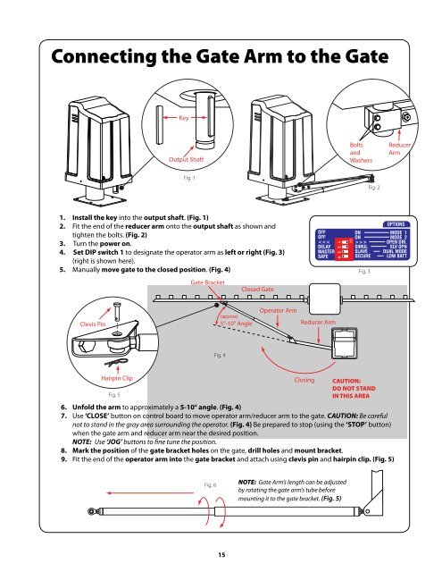
Connecting the <strong>Gate</strong> Arm to the <strong>Gate</strong><br />
Key<br />
Output Shaft<br />
Bolts<br />
and<br />
Washers<br />
Reducer<br />
Arm<br />
Fig. 1<br />
Fig. 2<br />
1. Install the key into the output shaft. (Fig. 1)<br />
2. Fit the end of the reducer arm onto the output shaft as shown and<br />
tighten the bolts. (Fig. 2)<br />
3. Turn the power on.<br />
4. Set DIP switch 1 to designate the operator arm as left or right (Fig. 3)<br />
(right is shown here).<br />
5. Manually move gate to the closed position. (Fig. 4)<br />
OFF<br />
OFF<br />
><br />
SIMUL<br />
SLAVE<br />
SECURE<br />
Fig. 3<br />
OPTIONS<br />
MODE 1<br />
MODE 2<br />
OPEN DIR.<br />
SLV OPN<br />
DUAL MODE<br />
LOW BATT<br />
<strong>Gate</strong> Bracket<br />
Closed <strong>Gate</strong><br />
Clevis Pin<br />
(approx)<br />
5°-10° Angle<br />
Operator Arm<br />
Reducer Arm<br />
Fig. 4<br />
Hairpin Clip<br />
Closing CAUTION:<br />
DO NOT STAND<br />
Fig. 5<br />
IN THIS AREA<br />
6. Unfold the arm to approximately a 5-10° angle. (Fig. 4)<br />
7. Use ‘CLOSE’ button on control board to move operator arm/reducer arm to the gate. CAUTION: Be careful<br />
not to stand in the gray area surrounding the operator. (Fig. 4) Be prepared to stop (using the ‘STOP’ button)<br />
when the gate arm and reducer arm near the desired position.<br />
NOTE: Use ‘JOG’ buttons to fine tune the position.<br />
8. Mark the position of the gate bracket holes on the gate, drill holes and mount bracket.<br />
9. Fit the end of the operator arm into the gate bracket and attach using clevis pin and hairpin clip. (Fig. 5)<br />
Fig. 6<br />
NOTE: <strong>Gate</strong> Arm’s length can be adjusted<br />
by rotating the gate arm’s tube before<br />
mounting it to the gate bracket. (Fig. 5)<br />
15