

Parts Sheet - You are now at the Down-Load Site for Tol-O - Tolomatic
Parts Sheet - You are now at the Down-Load Site for Tol-O - Tolomatic
Parts Sheet - You are now at the Down-Load Site for Tol-O - Tolomatic

Create successful ePaper yourself
Turn your PDF publications into a flip-book with our unique Google optimized e-Paper software.
2 – Install<strong>at</strong>ion & Maintenance CC05 <strong>Parts</strong> <strong>Sheet</strong> #1001-4000_06_CC05ps<br />
Install<strong>at</strong>ion<br />
When unpacking a <strong>Tol</strong>om<strong>at</strong>ic cable cylinder, BE EXTRA CAREFUL<br />
NOT TO SCRATCH OR MAR THE NYLON COVERING ON THE CABLE.<br />
The cylinder may be mounted using <strong>the</strong> bolt holes in <strong>the</strong> head. When<br />
<strong>at</strong>taching <strong>the</strong> cable bracket to <strong>the</strong> driven mechanism, be sure it is in<br />
perfect alignment and th<strong>at</strong> it does not deflect <strong>the</strong> cable to <strong>the</strong> side.<br />
Misalignment can cause excessive seal wear.<br />
Pretensioning and proof-loading instructions: All double-acting<br />
cable cylinders <strong>are</strong> shipped without being pretensioned. They must<br />
be pretensioned after mounting to insure maximum service life of<br />
<strong>the</strong> device. There <strong>are</strong> two types of stretch in cable— constructional<br />
and elastic. The constructional stretch is removed by proof-loading<br />
of <strong>the</strong> cable. The elastic stretch is removed by proper pretensioning<br />
of <strong>the</strong> cable.<br />
Proof-loading of cables (<strong>for</strong> cylinders without Auto Tensioners)<br />
1. Tighten <strong>the</strong> bracket terminal lock nuts equally with a torque<br />
wrench to torque requirements listed in Table A.<br />
2. Let set <strong>for</strong> 30 seconds.<br />
3. Loosen lock nuts to remove tension. (But leave <strong>the</strong>m tight<br />
enough to elimin<strong>at</strong>e any slack.)<br />
4. Follow Pretensioning Instructions.<br />
TABLE A: TORQUE TO PROOF-LOAD THE CABLE<br />
MODEL<br />
REQUIRED TORQUE<br />
CC05<br />
15 inch-pounds (1.69 Newton-meters)<br />
Pretensioning of cables:<br />
1. Block <strong>the</strong> load some distance from <strong>the</strong> end of travel to keep<br />
cylinder from bottoming.<br />
2. Apply pressure th<strong>at</strong> is 15-20 percent higher than actual load<br />
pressure needed to move <strong>the</strong> load.<br />
NOTE: <strong>Load</strong> pressure is defined as <strong>the</strong> actual pressure required to move <strong>the</strong><br />
load. When <strong>the</strong> load is stopped externally be<strong>for</strong>e <strong>the</strong> piston bottoms, <strong>the</strong> relief<br />
valve or regul<strong>at</strong>or setting becomes <strong>the</strong> load pressure.<br />
When pressurized, one cable becomes tight and <strong>the</strong> o<strong>the</strong>r becomes<br />
slack. Manually adjust out <strong>the</strong> slack. Release <strong>the</strong> pressure. Block<br />
<strong>the</strong> load on <strong>the</strong> opposite side and pressurize <strong>the</strong> o<strong>the</strong>r port. Repe<strong>at</strong><br />
<strong>the</strong> manual adjustment on <strong>the</strong> o<strong>the</strong>r cable. Release pressure and<br />
remove blocks. Return <strong>the</strong> regul<strong>at</strong>or or relief valve to <strong>the</strong> original<br />
load pressure.<br />
The cylinder is <strong>now</strong> pretensioned. Additional manual adjustment<br />
should not be required. It is suggested however, th<strong>at</strong> <strong>the</strong> cables be<br />
checked periodically.<br />
Altern<strong>at</strong>e Method: If <strong>the</strong> load cannot be blocked <strong>for</strong> cable<br />
pretensioning as st<strong>at</strong>ed above, tighten <strong>the</strong> bracket terminal lock nuts<br />
with a torque wrench to total pretensioning torque as st<strong>at</strong>ed in Table B.<br />
Model<br />
TABLE B: TORQUE FOR UNBLOCKABLE LOADS<br />
Pretensioning<br />
Torque +<br />
Starting Torque of<br />
Terminal Nuts =<br />
Total Pretensioning<br />
Torque<br />
CC05 2.5 in-lbs. + 10.0 in.-lbs. = 12.5 in.-lbs.<br />
.282 N-m + 1.130 N-m = 1.412 N-m<br />
NOTE: For cylinders with Auto Tensioners, <strong>the</strong> cables must be proofloaded<br />
and pretensioned be<strong>for</strong>e pressure is applied to <strong>the</strong> AT unit.<br />
TO REBUILD THE CYLINDER<br />
1. Remove cable cylinder from machinery.<br />
2. Disconnect Cable (1) from <strong>the</strong> Clevis (15) and remove Pulleys (4)<br />
on both ends of <strong>the</strong> cylinder.<br />
3. Remove internal retaining rings (16) from both heads and<br />
remove one head from cylinder by removing <strong>the</strong> four Socket<br />
Head Cap Screws (11)<br />
4. Pull Piston (13) towards <strong>the</strong> open tube end and remove from<br />
Tube (10).<br />
5. Disconnect Cables (1) from Piston (13) and pull back through<br />
<strong>the</strong> Heads (5) to remove <strong>the</strong>m.<br />
6. Install new U-cups (12) on Piston (13) and rethread new<br />
Cables (1) through Heads (5), and connect <strong>the</strong>m to <strong>the</strong><br />
Piston (13).<br />
7. Being c<strong>are</strong>ful not to damage <strong>the</strong> cable, lubric<strong>at</strong>e and install <strong>the</strong><br />
Gland Seals on <strong>the</strong> Cable Assembly (1) in <strong>the</strong> Heads (5), and<br />
reinstall <strong>the</strong> retaining rings (7).<br />
8. Push <strong>the</strong> Piston (13) back into Tube (10) by gently tucking in<br />
<strong>the</strong> U-cup (12) with a screwdriver or pencil. Mount head back<br />
on cylinder with Socket Head Cap Screws (11). Replace <strong>the</strong><br />
Pulleys (4) and connect Cable (1) to clevis (15).<br />
9. Oper<strong>at</strong>e cable cylinder back and <strong>for</strong>th by hand several times<br />
to be sure it is properly assembled be<strong>for</strong>e reconnecting air or<br />
hydraulic service.<br />
10. Reinstall cable cylinder on machinery.<br />
IMPORTANT NOTE: Apply (Blue) Loctite ® #242 or equivalent to<br />
threaded cable terminal be<strong>for</strong>e connecting to <strong>the</strong> piston.<br />
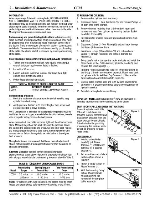
SNAP IN/OUT CABLE ASSEMBLY INSTRUCTIONS<br />
<strong>Tol</strong>om<strong>at</strong>ic cylinders with 1/2-,<br />
3/4- and 1-inch bores <strong>are</strong><br />
designed to allow assembly and<br />
disassembly of cables from <strong>the</strong><br />
8<br />
heads without <strong>the</strong> use of tools.<br />
7<br />
This elimin<strong>at</strong>es <strong>the</strong> possibility<br />
6<br />
5<br />
of damaging <strong>the</strong> cable or seals<br />
as well as providing <strong>for</strong> quick<br />
repair times.<br />
Disassembly:<br />
1. Holding onto cylinder<br />
Head (6), pull Piston<br />
Terminal (1) until Bracket<br />
Terminal (8) is against<br />
Washer (4).<br />
2. Put a small amount of slack<br />
in Cable (7) as shown in<br />
Figure 2.<br />
3. Impart a “snap” action to<br />
Piston Terminal (1).<br />
4. With <strong>the</strong> imparting “snap”<br />
action, Washer (2) will<br />
release allowing <strong>the</strong><br />
removal of <strong>the</strong> complete<br />
cable assembly.<br />
4<br />
3<br />
Figure 1.<br />
2<br />
1<br />
Figure 2.<br />
Figure 3.<br />
<strong>Tol</strong>om<strong>at</strong>ic • URL: http://www.tolom<strong>at</strong>ic.com • Email: help@tolom<strong>at</strong>ic.com • Fax: (763) 478-8080 • <strong>Tol</strong>l Free: 1-800-328-2174


