

Parts Sheet - You are now at the Down-Load Site for Tol-O - Tolomatic
Parts Sheet - You are now at the Down-Load Site for Tol-O - Tolomatic
Parts Sheet - You are now at the Down-Load Site for Tol-O - Tolomatic

You also want an ePaper? Increase the reach of your titles
YUMPU automatically turns print PDFs into web optimized ePapers that Google loves.
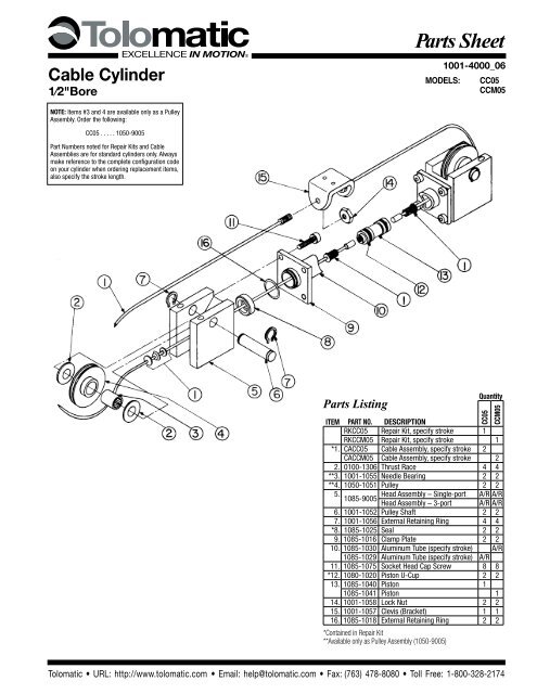
Cable Cylinder<br />
1⁄2"Bore<br />
<strong>Parts</strong> <strong>Sheet</strong><br />
1001-4000_06_CC05p<br />
MODELS: CC05<br />
CCM05<br />
NOTE: Items #3 and 4 <strong>are</strong> available only as a Pulley<br />
Assembly. Order <strong>the</strong> following:<br />
CC05 . . . . . 1050-9005<br />
Part Numbers noted <strong>for</strong> Repair Kits and Cable<br />
Assem blies <strong>are</strong> <strong>for</strong> standard cylinders only. Always<br />
make reference to <strong>the</strong> complete configur<strong>at</strong>ion code<br />
on your cylinder when ordering replacement items,<br />
also specify <strong>the</strong> stroke length.<br />
<strong>Parts</strong> Listing<br />
Quantity<br />
CC05<br />
CCM05<br />
ITEM PART NO. DESCRIPTION<br />
RKCC05 Repair Kit, specify stroke 1<br />
RKCCM05 Repair Kit, specify stroke 1<br />
*1. CACC05 Cable Assembly, specify stroke 2<br />
CACCM05 Cable Assembly, specify stroke 2<br />
2. 0100-1306 Thrust Race 4 4<br />
**3. 1001-1055 Needle Bearing 2 2<br />
**4. 1050-1051 Pulley 2 2<br />
5.<br />
Head Assembly – Single-port A/R A/R<br />
1085-9005<br />
Head Assembly – 3-port A/R A/R<br />
6. 1001-1052 Pulley Shaft 2 2<br />
7. 1001-1056 External Retaining Ring 4 4<br />
*8. 1085-1025 Seal 2 2<br />
9. 1085-1016 Clamp Pl<strong>at</strong>e 2 2<br />
10. 1085-1030 Aluminum Tube (specify stroke) A/R<br />
1085-1029 Aluminum Tube (specify stroke) A/R<br />
11. 1085-1075 Socket Head Cap Screw 8 8<br />
*12. 1080-1020 Piston U-Cup 2 2<br />
13. 1085-1040 Piston 1<br />
1085-1041 Piston 1<br />
14. 1001-1058 Lock Nut 2 2<br />
15. 1001-1057 Clevis (Bracket) 1 1<br />
16. 1085-1018 External Retaining Ring 2 2<br />
*Contained in Repair Kit<br />
**Available only as Pulley Assembly (1050-9005)<br />
<strong>Tol</strong>om<strong>at</strong>ic • URL: http://www.tolom<strong>at</strong>ic.com • Email: help@tolom<strong>at</strong>ic.com • Fax: (763) 478-8080 • <strong>Tol</strong>l Free: 1-800-328-2174
2 – Install<strong>at</strong>ion & Maintenance CC05 <strong>Parts</strong> <strong>Sheet</strong> #1001-4000_06_CC05ps<br />
Install<strong>at</strong>ion<br />
When unpacking a <strong>Tol</strong>om<strong>at</strong>ic cable cylinder, BE EXTRA CAREFUL<br />
NOT TO SCRATCH OR MAR THE NYLON COVERING ON THE CABLE.<br />
The cylinder may be mounted using <strong>the</strong> bolt holes in <strong>the</strong> head. When<br />
<strong>at</strong>taching <strong>the</strong> cable bracket to <strong>the</strong> driven mechanism, be sure it is in<br />
perfect alignment and th<strong>at</strong> it does not deflect <strong>the</strong> cable to <strong>the</strong> side.<br />
Misalignment can cause excessive seal wear.<br />
Pretensioning and proof-loading instructions: All double-acting<br />
cable cylinders <strong>are</strong> shipped without being pretensioned. They must<br />
be pretensioned after mounting to insure maximum service life of<br />
<strong>the</strong> device. There <strong>are</strong> two types of stretch in cable— constructional<br />
and elastic. The constructional stretch is removed by proof-loading<br />
of <strong>the</strong> cable. The elastic stretch is removed by proper pretensioning<br />
of <strong>the</strong> cable.<br />
Proof-loading of cables (<strong>for</strong> cylinders without Auto Tensioners)<br />
1. Tighten <strong>the</strong> bracket terminal lock nuts equally with a torque<br />
wrench to torque requirements listed in Table A.<br />
2. Let set <strong>for</strong> 30 seconds.<br />
3. Loosen lock nuts to remove tension. (But leave <strong>the</strong>m tight<br />
enough to elimin<strong>at</strong>e any slack.)<br />
4. Follow Pretensioning Instructions.<br />
TABLE A: TORQUE TO PROOF-LOAD THE CABLE<br />
MODEL<br />
REQUIRED TORQUE<br />
CC05<br />
15 inch-pounds (1.69 Newton-meters)<br />
Pretensioning of cables:<br />
1. Block <strong>the</strong> load some distance from <strong>the</strong> end of travel to keep<br />
cylinder from bottoming.<br />
2. Apply pressure th<strong>at</strong> is 15-20 percent higher than actual load<br />
pressure needed to move <strong>the</strong> load.<br />
NOTE: <strong>Load</strong> pressure is defined as <strong>the</strong> actual pressure required to move <strong>the</strong><br />
load. When <strong>the</strong> load is stopped externally be<strong>for</strong>e <strong>the</strong> piston bottoms, <strong>the</strong> relief<br />
valve or regul<strong>at</strong>or setting becomes <strong>the</strong> load pressure.<br />
When pressurized, one cable becomes tight and <strong>the</strong> o<strong>the</strong>r becomes<br />
slack. Manually adjust out <strong>the</strong> slack. Release <strong>the</strong> pressure. Block<br />
<strong>the</strong> load on <strong>the</strong> opposite side and pressurize <strong>the</strong> o<strong>the</strong>r port. Repe<strong>at</strong><br />
<strong>the</strong> manual adjustment on <strong>the</strong> o<strong>the</strong>r cable. Release pressure and<br />
remove blocks. Return <strong>the</strong> regul<strong>at</strong>or or relief valve to <strong>the</strong> original<br />
load pressure.<br />
The cylinder is <strong>now</strong> pretensioned. Additional manual adjustment<br />
should not be required. It is suggested however, th<strong>at</strong> <strong>the</strong> cables be<br />
checked periodically.<br />
Altern<strong>at</strong>e Method: If <strong>the</strong> load cannot be blocked <strong>for</strong> cable<br />
pretensioning as st<strong>at</strong>ed above, tighten <strong>the</strong> bracket terminal lock nuts<br />
with a torque wrench to total pretensioning torque as st<strong>at</strong>ed in Table B.<br />
Model<br />
TABLE B: TORQUE FOR UNBLOCKABLE LOADS<br />
Pretensioning<br />
Torque +<br />
Starting Torque of<br />
Terminal Nuts =<br />
Total Pretensioning<br />
Torque<br />
CC05 2.5 in-lbs. + 10.0 in.-lbs. = 12.5 in.-lbs.<br />
.282 N-m + 1.130 N-m = 1.412 N-m<br />
NOTE: For cylinders with Auto Tensioners, <strong>the</strong> cables must be proofloaded<br />
and pretensioned be<strong>for</strong>e pressure is applied to <strong>the</strong> AT unit.<br />
TO REBUILD THE CYLINDER<br />
1. Remove cable cylinder from machinery.<br />
2. Disconnect Cable (1) from <strong>the</strong> Clevis (15) and remove Pulleys (4)<br />
on both ends of <strong>the</strong> cylinder.<br />
3. Remove internal retaining rings (16) from both heads and<br />
remove one head from cylinder by removing <strong>the</strong> four Socket<br />
Head Cap Screws (11)<br />
4. Pull Piston (13) towards <strong>the</strong> open tube end and remove from<br />
Tube (10).<br />
5. Disconnect Cables (1) from Piston (13) and pull back through<br />
<strong>the</strong> Heads (5) to remove <strong>the</strong>m.<br />
6. Install new U-cups (12) on Piston (13) and rethread new<br />
Cables (1) through Heads (5), and connect <strong>the</strong>m to <strong>the</strong><br />
Piston (13).<br />
7. Being c<strong>are</strong>ful not to damage <strong>the</strong> cable, lubric<strong>at</strong>e and install <strong>the</strong><br />
Gland Seals on <strong>the</strong> Cable Assembly (1) in <strong>the</strong> Heads (5), and<br />
reinstall <strong>the</strong> retaining rings (7).<br />
8. Push <strong>the</strong> Piston (13) back into Tube (10) by gently tucking in<br />
<strong>the</strong> U-cup (12) with a screwdriver or pencil. Mount head back<br />
on cylinder with Socket Head Cap Screws (11). Replace <strong>the</strong><br />
Pulleys (4) and connect Cable (1) to clevis (15).<br />
9. Oper<strong>at</strong>e cable cylinder back and <strong>for</strong>th by hand several times<br />
to be sure it is properly assembled be<strong>for</strong>e reconnecting air or<br />
hydraulic service.<br />
10. Reinstall cable cylinder on machinery.<br />
IMPORTANT NOTE: Apply (Blue) Loctite ® #242 or equivalent to<br />
threaded cable terminal be<strong>for</strong>e connecting to <strong>the</strong> piston.<br />
SNAP IN/OUT CABLE ASSEMBLY INSTRUCTIONS<br />
<strong>Tol</strong>om<strong>at</strong>ic cylinders with 1/2-,<br />
3/4- and 1-inch bores <strong>are</strong><br />
designed to allow assembly and<br />
disassembly of cables from <strong>the</strong><br />
8<br />
heads without <strong>the</strong> use of tools.<br />
7<br />
This elimin<strong>at</strong>es <strong>the</strong> possibility<br />
6<br />
5<br />
of damaging <strong>the</strong> cable or seals<br />
as well as providing <strong>for</strong> quick<br />
repair times.<br />
Disassembly:<br />
1. Holding onto cylinder<br />
Head (6), pull Piston<br />
Terminal (1) until Bracket<br />
Terminal (8) is against<br />
Washer (4).<br />
2. Put a small amount of slack<br />
in Cable (7) as shown in<br />
Figure 2.<br />
3. Impart a “snap” action to<br />
Piston Terminal (1).<br />
4. With <strong>the</strong> imparting “snap”<br />
action, Washer (2) will<br />
release allowing <strong>the</strong><br />
removal of <strong>the</strong> complete<br />
cable assembly.<br />
4<br />
3<br />
Figure 1.<br />
2<br />
1<br />
Figure 2.<br />
Figure 3.<br />
<strong>Tol</strong>om<strong>at</strong>ic • URL: http://www.tolom<strong>at</strong>ic.com • Email: help@tolom<strong>at</strong>ic.com • Fax: (763) 478-8080 • <strong>Tol</strong>l Free: 1-800-328-2174
<strong>Parts</strong> <strong>Sheet</strong> #1001-4000_06_CC05ps CC05 Install<strong>at</strong>ion, Maintenance and Switch Option – 3<br />
Reassembly:<br />
1. Holding onto cylinder Head (6), string Bracket Terminal (8)<br />
through Gland (5) until Washer (4), U-cup (3) and Washer (2) <strong>are</strong><br />
held flush against one ano<strong>the</strong>r by Piston Terminal (1).<br />
2. Put a small amount of slack in Cable (7) as shown in Figure 3.<br />
3. Impart a “snap” action to Bracket Terminal (8).<br />
4. With <strong>the</strong> imparting “snap” action, Washer (2) will snap into<br />
Gland (5).<br />
5. Move <strong>the</strong> cable in <strong>the</strong> opposite direction as shown in Figure 3,<br />
to verify if Washer (2) is se<strong>at</strong>ed in Gland (5). If not, repe<strong>at</strong> steps<br />
1-4.<br />
MAINTENANCE<br />
Keep <strong>the</strong> cylinder as clean as possible around pulleys, glands, etc.<br />
Pneum<strong>at</strong>ic service should be adequ<strong>at</strong>ely lubric<strong>at</strong>ed with SAE 10 or<br />
20 grade non-detergent oil. Pulleys have permanently lubric<strong>at</strong>ed<br />
bearings and will require no maintenance. Check <strong>the</strong> cylinder’s<br />
cables periodically to help prevent prem<strong>at</strong>ure or unexpected failures.<br />
<strong>You</strong>r <strong>Tol</strong>om<strong>at</strong>ic Cable Cylinder will give you many cycles of trouble<br />
free service. However, should a leak occur, a rebuilding kit may be<br />
obtained which enables you to replace all <strong>the</strong> seals in a cylinder to<br />
return it to normal oper<strong>at</strong>ing condition.<br />
NOTE: Every <strong>Tol</strong>om<strong>at</strong>ic Cable Cylinder has its stroke length indic<strong>at</strong>ed<br />
on <strong>the</strong> identific<strong>at</strong>ion tag shipped with <strong>the</strong> cylinder. Refer to this<br />
stroke measurement when ordering replacement parts <strong>for</strong> <strong>the</strong> cable<br />
cylinder.<br />
Should <strong>the</strong> tag be missing, measure <strong>the</strong> length of <strong>the</strong> cylinder<br />
including <strong>the</strong> heads <strong>at</strong> both ends. If <strong>the</strong>re <strong>are</strong> no switches present on<br />
<strong>the</strong> cylinder, check <strong>the</strong> piston <strong>for</strong> a magnet to see if it is a Reed Switch<br />
model. If it is, consult <strong>the</strong> <strong>Tol</strong>om<strong>at</strong>ic Cable Cylinder c<strong>at</strong>alog dimensional<br />
drawings <strong>for</strong> “stroke-plus” length and subtract 1.62 inches <strong>for</strong><br />
cylinders with 1/2-inch 3/4-inch and 1-inch bores and .375 inches <strong>for</strong><br />
all larger bore Reed Switch models to determine <strong>the</strong> stroke length.<br />
Switch Option<br />
20<br />
19<br />
ITEM PART NO. DESCRIPTION Quantity<br />
18. 1080-1012 Magnet 4<br />
19. 2503-1039 Switch Hardw<strong>are</strong> Kit 1<br />
REED SWITCHES<br />
NOTE: Form A Reed Switches should not be used in TTL logic<br />
circuits. A voltage drop caused by <strong>the</strong> L.E.D. indic<strong>at</strong>or will result.For<br />
applic<strong>at</strong>ions where TTL circuits <strong>are</strong> used, please contact <strong>Tol</strong>om<strong>at</strong>ic.<br />
WARNING: An ohmmeter is recommended <strong>for</strong> testing Reed<br />
Switches. NEVER use an incandescent light bulb as a high current<br />
rush may damage <strong>the</strong> switch.<br />
Reed and TRIAC switches <strong>are</strong> only recommended <strong>for</strong> signalling<br />
position, not directly powering soleniods. For shifting a solenoid, a<br />
relay or resistor is recommended between it and <strong>the</strong> switch. Switch<br />
r<strong>at</strong>ings must not be exceeded <strong>at</strong> any time<br />
Part Number Ordering Config. Code Ordering<br />
No Mounting Hardw<strong>are</strong> or FE conn. included Mounting Hardw<strong>are</strong> & FE conn. included<br />
item Part NO. Description Code<br />
20. 3600-9084 Switch Only, Reed, Form C, 5m BT<br />
3600-9085 Switch Only, Reed, Form C, QD Male Conn. BM<br />
3600-9082 Switch Only, Reed, Form A, 5m RT<br />
3600-9083 Switch Only, Reed, Form A, QD Male Conn. RM<br />
3600-9086 Switch Only, Triac, 5m CT<br />
3600-9087 Switch Only, Triac, QD Male Conn. CM<br />
2503-1025 Connector (Female) 5 meter lead<br />
NOTE: When ordered by Config. Code Female connector & all mounting hardw<strong>are</strong> is included<br />
TO ORDER RETROFIT KITS: SW (<strong>the</strong>n <strong>the</strong> model number and base<br />
size, and code <strong>for</strong> type of switch needed: EXAMPLE: SWCC05RT<br />
All Switch Kits come with 1 switch and mounting hardw<strong>are</strong>.<br />
Hardw<strong>are</strong> Only Kits <strong>are</strong> available:<br />
CCM05 - 2503-1039<br />
<strong>Tol</strong>om<strong>at</strong>ic • URL: http://www.tolom<strong>at</strong>ic.com • Email: help@tolom<strong>at</strong>ic.com • Fax: (763) 478-8080 • <strong>Tol</strong>l Free: 1-800-328-2174
4 – Switches CC05<br />
<strong>Parts</strong> <strong>Sheet</strong> #1001-4000_06_CC05ps<br />
Universal Switch Wiring Diagrams and Label Color Coding<br />
(+)<br />
(-)<br />
OR<br />
(+)<br />
(-)<br />
LOAD<br />
LOAD<br />
BROWN<br />
(+)<br />
BLUE<br />
(-)<br />
BROWN<br />
(+)<br />
BLUE<br />
(-)<br />
REED<br />
SWITCH<br />
REED<br />
SWITCH<br />
REED SWITCH FORM A<br />
LABEL COLOR: RED<br />
10VA MAX.<br />
200 Vdc<br />
500mA Max. Current<br />
NOTE: The side of <strong>the</strong> switch with <strong>the</strong><br />
groove indic<strong>at</strong>es <strong>the</strong> sensing surface.<br />
This must face toward <strong>the</strong> magnet.<br />
COMMON<br />
NORMALLY CLOSED<br />
NORMALLY OPEN<br />
BROWN<br />
BLACK<br />
BLUE<br />
REED<br />
SWITCH<br />
REED SWITCH FORM C<br />
LABEL COLOR: YELLOW<br />
120 Vdc/120 Vac MAX.<br />
250mA Max. Current<br />
120Vac<br />
Max.<br />
BLUE<br />
MOV<br />
TRIAC<br />
SWITCH<br />
BROWN<br />
AC<br />
COM<br />
LOAD<br />
INPUT<br />
TRIAC SWITCH<br />
LABEL COLOR: BLUE<br />
Max. 1Amp. Cont. Current @ 86°F<br />
Max. .5Amp. Cont. Current @ 140°F<br />
Peak surge current 10Amp.<br />
For complete Reed and TRIAC Switch Per<strong>for</strong>mance D<strong>at</strong>a, refer<br />
to <strong>the</strong> <strong>Tol</strong>om<strong>at</strong>ic Pneum<strong>at</strong>ic Products C<strong>at</strong>alog #9900-4000.<br />
Loctite ® is a registered trademark of <strong>the</strong> Loctite Corpor<strong>at</strong>ion, www.loctite.com<br />
Viton ® is a registered trademark of <strong>the</strong> E.I. Du Pont de Newmours Co., www.dupont.com<br />
BLUE<br />
BLACK<br />
BROWN<br />
QUICK-DISCONNECT<br />
(Applies to all switch types)<br />
An Important Note Regarding Field<br />
Retrofit of Quick-Disconnect<br />
Couplers:<br />
If replacing a Quick-Disconnect<br />
switch manufactured be<strong>for</strong>e 7-1-97 it<br />
will also be necessary to replace or<br />
rewire <strong>the</strong> female-end coupler with<br />
<strong>the</strong> in-line splice<br />
2503-1025 Female Connector 5M<br />
BT<br />
BM<br />
RT<br />
SWITCH TYPE CODE<br />
(Form C Reed Switch with 5-meter lead)<br />
RM (Form A Reed Switch with 5-meter lead and QD)<br />
(Form C Reed Switch with 5-meter lead and QD) CT (TRIAC Switch with 5-meter lead)<br />
(Form A Reed Switch with 5-meter lead)<br />
CM (TRIAC Switch with 5-meter lead and QD)<br />
3800 County Road 116, Hamel, MN 55340<br />
http://www.<strong>Tol</strong>om<strong>at</strong>ic.com • Email: Help@<strong>Tol</strong>om<strong>at</strong>ic.com<br />
Phone: (763) 478-8000 • Fax: (763) 478-8080 • <strong>Tol</strong>l Free: 1-800-328-2174<br />
© 2010 <strong>Tol</strong>om<strong>at</strong>ic 201011220808<br />
8<br />
In<strong>for</strong>m<strong>at</strong>ion furnished is believed to be accur<strong>at</strong>e<br />
and reliable. However, <strong>Tol</strong>om<strong>at</strong>ic assumes no<br />
responsibility <strong>for</strong> its use or <strong>for</strong> any errors th<strong>at</strong><br />
may appear in this document. <strong>Tol</strong>om<strong>at</strong>ic reserves<br />
<strong>the</strong> right to change <strong>the</strong> design or oper<strong>at</strong>ion of <strong>the</strong><br />
equipment described herein and any associ<strong>at</strong>ed<br />
motion products without notice. In<strong>for</strong>m<strong>at</strong>ion in<br />
this document is subject to change without notice.


