High power RF-LDMOS transistors for base station applications
High power RF-LDMOS transistors for base station applications
High power RF-LDMOS transistors for base station applications

You also want an ePaper? Increase the reach of your titles
YUMPU automatically turns print PDFs into web optimized ePapers that Google loves.
semiconductors<br />
<strong>High</strong> <strong>power</strong> <strong>RF</strong>-<strong>LDMOS</strong> <strong>transistors</strong><br />
<strong>for</strong> <strong>base</strong> <strong>station</strong> <strong>applications</strong><br />
Delivering the <strong>power</strong> <strong>for</strong> upcoming wideband high-capacity <strong>base</strong> <strong>station</strong>s that will<br />
provide the punch <strong>for</strong> high bit-rate in<strong>for</strong>mation systems.<br />
By Christopher P. Dragon,<br />
Wayne R. Burger,<br />
Bob Davidson, Enver Krvavac,<br />
Nagaraj Dixit and Dale Joersz<br />
With trials ongoing in Japan <strong>for</strong><br />
IMT-2000 and similar activity <strong>for</strong><br />
UMTS starting soon in Europe, the<br />
2.11 to 2.17 GHz band <strong>for</strong> wideband<br />
code division-multiple access (W-<br />
CDMA) is getting considerable attention<br />
from infrastructure <strong>base</strong> <strong>station</strong><br />
OEMs and high <strong>power</strong> <strong>RF</strong> transistor<br />
manufacturers. As third generation<br />
(3G) cellular systems such as W-CDMA<br />
are emerging, the demand <strong>for</strong> <strong>transistors</strong><br />
with increased output <strong>power</strong> has<br />
escalated in support of the <strong>RF</strong> <strong>power</strong><br />
amplifier designs required <strong>for</strong> <strong>base</strong> <strong>station</strong><br />
infrastructure.<br />
The technical design and high volume<br />
fabrication of <strong>transistors</strong> that<br />
meet this demand pose a specific set of<br />
challenges. The devices must be efficient<br />
and possess a high degree of linearity.<br />
Reasonably high impedances<br />
must be presented to the input/output<br />
terminals <strong>for</strong> ease of use, thermal management<br />
and reliability. Device consistency<br />
and cost are also important factors<br />
<strong>for</strong> consideration.<br />
For several years, <strong>RF</strong>-<strong>LDMOS</strong> has<br />
been a leading technology used in support<br />
of high <strong>power</strong> <strong>RF</strong> <strong>applications</strong>,<br />
specifically <strong>for</strong> cellular <strong>base</strong> <strong>station</strong><br />
<strong>power</strong> amplifiers [1], [2]. Breakdown<br />
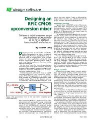
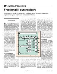
Figure 1. Cross-section of a typical <strong>LDMOS</strong><br />
structure.<br />
voltages in excess of 65 V facilitate the<br />
use of a 28 V <strong>power</strong> supply while maintaining<br />
superior ruggedness characteristics.<br />
The p+ sinker (see Figure 1) provides<br />
a low inductance path to ground,<br />
and the inherent device linearity has<br />
been used to great advantage.<br />
This article discusses the parameters<br />
that are considered critical <strong>for</strong> superior<br />
W-CDMA per<strong>for</strong>mance and presents<br />
the per<strong>for</strong>mance of a leading-edge <strong>RF</strong>-<br />
<strong>LDMOS</strong> device design. The device<br />
described here operates single-ended<br />
(see Figures 2 and 3) and delivers 155<br />
W, or 51.9 dBm of CW output <strong>power</strong> at<br />
3 dB compression (P 3dB ) and 2.12 GHz.<br />
Die technology is <strong>base</strong>d on a fourthgeneration<br />
process that uses a 40 nm<br />
gate oxide, 0.6 µm gate length, die<br />
thickness of 100 µm, and a total gate<br />
periphery of 360 mm.<br />
Linearity<br />
Be<strong>for</strong>e the emergence of spread-spectrum<br />
wireless protocols, a widely<br />
accepted figure of merit <strong>for</strong> linearity in<br />
class AB amplifiers was two-tone intermodulation<br />
distortion (IMD). This measurement<br />
is done with an input signal<br />
consisting of two unmodulated carriers<br />
spaced 100 kHz apart. Wide bandwidth<br />
modulation <strong>for</strong>mats, as well as widely<br />
spaced carriers, have brought about the<br />
need to design the amplifier circuit so<br />
this measurement can be made using<br />
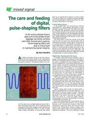
much wider tone separations. Figure 4<br />
shows IMD, using 10 MHz tone spacing<br />
(f 1 = 2.115 GHz, f 2 = 2.125 GHz), plotted<br />
against output <strong>power</strong> <strong>for</strong> several different<br />
quiescent drain bias currents<br />
(IDQ). Figure 5 shows the corresponding<br />
gain <strong>for</strong> the same variations in quiescent<br />
drain bias current. Also note<br />
that output <strong>power</strong> <strong>for</strong> this type of signal<br />
is maximized at a bias current of about<br />
1.0 A.<br />
CDMA and W-CDMA signals produce<br />
distortion products that are<br />
spread across a continuous spectrum of<br />
frequencies. This is observed as spectral<br />
regrowth on either side of the single<br />
carrier band. (See Figure 6.) This<br />
dictates that adjacent channel <strong>power</strong><br />
ratio (ACPR), calculated by integrating<br />
the <strong>power</strong> in 3.84 MHz bandwidths offset<br />
5 MHz from the W-CDMA channel<br />
and dividing by the channel <strong>power</strong>, is<br />
used rather than IMD as a measure of<br />
linearity. Figure 7 shows ACPR versus<br />
output <strong>power</strong> <strong>for</strong> the single-ended<br />
device with a drain bias of 1.3 A. The<br />
device achieves an average output<br />
<strong>power</strong> of 44.2 dBm (26.4 W) at –45 dBc<br />
ACPR with an efficiency of 21.9%.<br />
Referring to Figure 4, note this bias<br />
point corresponds to two-tone IMD per<strong>for</strong>mance<br />
less than –45 dBc <strong>for</strong> <strong>power</strong>s<br />
roughly 8 dB or more below P 3dB . This<br />
is important because the peak-to-average<br />
<strong>power</strong> ratio of these spread-spectrum<br />
signals is in the 10 dB region,<br />
making the two-tone linearity per<strong>for</strong>-<br />
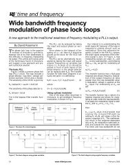
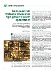
Figure 2. The internal configuration of a 155 W<br />
transistor.<br />
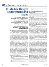
Figure 3. Transistor <strong>for</strong>m factor.<br />
20 www.rfdesign.com March 2000
Figure 4. Class-AB two-tone intermodulation<br />
distortion versus output <strong>power</strong> as a function<br />
of drain bias.<br />
mance of the device in the region 8 dB<br />
to 10 dB below P 3dB a good indicator of<br />
CDMA <strong>power</strong> capability. Moreover, the<br />
excellent linearity of <strong>RF</strong>-<strong>LDMOS</strong><br />
devices in this so-called “back off”<br />
region contributes to minimizing the<br />
complexity of the total amplifier system<br />
and maximizing system efficiency.<br />
Additional considerations <strong>for</strong> linearity<br />
per<strong>for</strong>mance using wide modulation<br />
bandwidths or widely separated signals<br />
are gain and phase flatness. These<br />
parameters were measured over the<br />
band of 2.11 GHz to 2.17 GHz and<br />
found to be 0.20 dB and 0.42 degrees<br />
respectively.<br />
Furthermore, many W-CDMA <strong>base</strong><br />
<strong>station</strong>s are designed to operate with<br />
several carriers adjacent to one another.<br />
Intermodulation distortion caused by<br />
two spread-spectrum signals is certain to<br />
occur under these conditions, and there<strong>for</strong>e,<br />
must be quantified if the device linearity<br />
is to be characterized fully.<br />
From a system point of view, two W-<br />
CDMA carriers with a spacing of 10<br />
MHz represent a worst-case situation.<br />
Two W-CDMA carriers at f 1 = 2.1125<br />
GHz and f 2 = 2.1225 GHz were used to<br />
generate the data plotted in Figure 8.<br />
The IMD of the third-order products<br />
(IMD3) is calculated by integrating the<br />
<strong>power</strong> in 3.84 MHz bandwidths at<br />
2.1325 GHz (IMD3+) and 2.1025 GHz<br />
(IMD3–), and is plotted along with efficiency<br />
and ACPR against output <strong>power</strong><br />
Figure 5. Class-AB two-tone <strong>power</strong> gain versus<br />
output <strong>power</strong> as a function of drain bias.<br />
in Figure 9. It is clear that the IMD3,<br />
as measured under these conditions,<br />
tracks ACPR. Note that the drain bias<br />
<strong>for</strong> the two carrier measurement has<br />
been increased to 1.6 A, which is<br />
slightly higher than the 1.3 A used to<br />
achieve the best single carrier W-<br />
CDMA per<strong>for</strong>mance. The ACPR reaches<br />
–40 dBc at 44.6 dBm (29.0 W) at<br />
22.9% efficiency, whereas the IMD3<br />
generated between two adjacent multicarrier<br />
stimuli reaches –40 dBc at 43.7<br />
dBm (23.7 W) and 20.5% efficiency.<br />
Choosing which metric to use and the<br />
appropriate bias point should be application-driven.<br />
Output <strong>power</strong><br />
While the average <strong>power</strong> per sector<br />
and/or carrier in W-CDMA systems is<br />
relatively low, the high peak-to-average<br />
ratio of the signal requires <strong>transistors</strong><br />
with state-of-the-art, peak <strong>power</strong> capabilities.<br />
Multicarrier systems require<br />
designers to continually strive <strong>for</strong><br />
increased <strong>power</strong> capability from their<br />
<strong>power</strong> amplifiers (PA’s). Delivering<br />
transistor solutions that generate larger<br />
and larger amounts of output <strong>power</strong><br />
assists designers in achieving this goal.<br />
Output <strong>power</strong> can be defined under<br />
several different conditions, one of<br />
which is the previously defined P 3dB .<br />
Figure10 shows the constant envelope<br />
or continuous wave (CW) output <strong>power</strong><br />
capability of the single-ended design.<br />
The broadband capability of the device,<br />
along with excellent flatness, is further<br />
shown in Figure 11 under conventional<br />
two-tone conditions. Although GSM<br />
<strong>base</strong> <strong>station</strong>s operate at elevated average<br />
<strong>power</strong> levels (because of the constant<br />
envelope nature of the signal),<br />
CDMA and W-CDMA <strong>base</strong> <strong>station</strong>s<br />
maintain low average <strong>power</strong> levels due<br />
to the linearity requirements imposed<br />
by their spread-spectrum nature.<br />
Referring back to Figure 9, an average<br />
<strong>power</strong> of 23.7 W (or 8.2 dB below<br />
P 3dB ) is achieved under W-CDMA conditions<br />
when a linearity constraint of<br />
IMD3 +/- of –40 dBc or better is used.<br />
Note the continuing reduction in IMD3<br />
with decreasing <strong>power</strong> illustrating the<br />
excellent linearity properties of the <strong>RF</strong>-<br />
<strong>LDMOS</strong> technology. The system<br />
designer must carefully consider the<br />
overall system architecture, including<br />
error correction, to determine the optimum<br />
operating point.<br />
For a given supply voltage, increasing<br />
device size is the most straight<strong>for</strong>ward<br />
method used to increase a<br />
device’s <strong>power</strong> capability. However,<br />
when a fixed amount of <strong>power</strong> is<br />
required, caution must be exercised<br />
not to make the device too large or<br />
efficiency will be degraded. An additional<br />
challenge facing the device<br />
designer is ensuring these very high<br />
<strong>power</strong> devices can achieve the specified<br />
levels of per<strong>for</strong>mance when<br />
acceptable levels of circuit impedances<br />
are presented to the I/O terminals. For<br />
the device described in this article, the<br />
layout design of the die incorporates<br />
two large metal bus pads <strong>for</strong> the drain<br />
and gate connections. These bus pads<br />
allow advanced topology impedance<br />
matching to be designed into the<br />
device package. The resulting<br />
input/output impedances achieved<br />
across the W-CDMA band are shown<br />
in Table 1 (Note the typical Q is 1.8 <strong>for</strong><br />
Z in and 1.25 <strong>for</strong> Z out .<br />
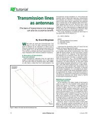
Figure 6. Example of spectral regrowth when<br />
driven by a CDMA signal.<br />
Figure 7. ACPR and drain efficiency <strong>for</strong> one W-<br />
CDMA carrier versus output <strong>power</strong>.<br />
Figure 8. Two W-CDMA carriers showing IMD3<br />
and spectral regrowth.<br />
22 www.rfdesign.com March 2000
Drain efficiency<br />
Drain efficiency has always been a<br />
critical parameter <strong>for</strong> PA devices, mainly<br />
due to thermal management issues that<br />
must be addressed at both the device<br />
and the system levels in such high-<strong>power</strong><br />
designs. Referring to Figure 10, the<br />
drain efficiency of the device is plotted<br />
against CW input <strong>power</strong>. At the P 3dB<br />
point, an efficiency of 49% is achieved.<br />
Under W-CDMA conditions however, the<br />
average <strong>power</strong> is much lower and highly<br />
dependent on the linearity constraint.<br />
This reveals a direct trade off between<br />
linearity and efficiency. In the previous<br />
section, a constraint of –40 dBc IMD3<br />
was used (see Figure 9) to define an<br />
average <strong>power</strong> capability of 23.7 W. The<br />
corresponding efficiency is indicated as<br />
20.5%. A higher efficiency operating<br />
point can be achieved by relaxing the linearity<br />
criteria. For example, at –35 dBc<br />
IMD3, output <strong>power</strong> is 45.1 dBm (32.2<br />
watts) and efficiency has increased to<br />
22.9%. Whether this really improves the<br />
overall system level efficiency must be<br />
carefully evaluated in terms of the additional<br />
error correction required to maintain<br />
the system linearity specification.<br />
Conclusion<br />
<strong>RF</strong>-<strong>LDMOS</strong> technology enables the<br />
design of high-<strong>power</strong>, high-linearity <strong>RF</strong><br />
<strong>power</strong> amplifiers without compromising<br />
system level <strong>power</strong> conversion efficiency.<br />
Linear amplifiers of this type, using <strong>RF</strong>-<br />
<strong>LDMOS</strong>, are believed to be as cost effective<br />
as possible. This article has illustrated<br />
the excellent linearity character-<br />
Figure 9. IMD3, ACPR and drain efficiency <strong>for</strong> two<br />
W-CDMA carriers vs. output <strong>power</strong>.<br />
Figure 10. Single-tone output <strong>power</strong>, gain and<br />
efficiency versus input <strong>power</strong>.<br />
Figure 11. Broadband two-tone per<strong>for</strong>mance.<br />
24 March 2000
Frequency Z in (W) Z out (W)<br />
2.11 GHz 3.81 +j6.85 1.56 -j1.58<br />
2.14 GHz 4.33 +j7.90 1.53 -j1.90<br />
2.17 GHz 4.84 +j8.46 1.48 -j2.26<br />
Table 1. Input and output impedances.<br />
istics of <strong>RF</strong>-<strong>LDMOS</strong> at high-<strong>power</strong> levels<br />
and discussed some of the <strong>RF</strong> per<strong>for</strong>mance<br />
measurements and tradeoffs that<br />
face the system designer in selecting the<br />
optimum operating point <strong>for</strong> the transistor.<br />
State-of-the-art <strong>RF</strong>-<strong>LDMOS</strong> results<br />
have been presented <strong>for</strong> a single-ended<br />
transistor capable of delivering P3dB<br />
levels of 155 W along with W-CDMA<br />
<strong>power</strong> levels at –40 dBc IMD3 of 23.7<br />
watts. Further, note that the average W-<br />
CDMA <strong>power</strong> <strong>for</strong> the stated linearity criteria<br />
is 8.2 dB below the P 3dB value,<br />
which is nearly identical to the peak to<br />
average ratio of the W-CDMA test signal<br />
used in these measurements.<br />
References<br />
[1] A. Wood, C. Dragon, and W.<br />
Burger, “<strong>High</strong> Per<strong>for</strong>mance Silicon<br />
<strong>LDMOS</strong> Technology <strong>for</strong> 2GHz <strong>RF</strong><br />
Power Amplifier Applications”, IEDM<br />
Tech. Digest 1996, pp. 87-90.<br />
[2] A. Wood, W. Brakensiek, C.<br />
Dragon, and W. Burger, “120 Watt,<br />
2GHz, Si <strong>LDMOS</strong> <strong>RF</strong> Power Transistor<br />
<strong>for</strong> PCS Base <strong>station</strong> Applications,<br />
1998 IEEE MTT-S Digest, pp. 707-710.<br />
About the authors<br />
Christopher P. Dragon is a <strong>RF</strong><br />
Device Engineer He received his<br />
BSEE (LSU); Masters of Engineering<br />
(ME)in Microelectronic Engineering<br />
(RIT). He can be reached at (480)413-<br />
6887. e-mail Chris.Dragon@<br />
motorola.com.<br />
Bob Davidson is a Member of The<br />
Technical Staf. He received his BSEE<br />
from the University of Illinois atUrbana<br />
in 1975 and MSEE from Illinois<br />
Institute of Technology, Chicago in<br />
1979. He can be reached at (480) 413-<br />
5602. e-mail Bob.Davidson@<br />
motorola.com.<br />
Wayne Burger is a <strong>RF</strong> <strong>LDMOS</strong><br />
Device Engineering Manager. He<br />
received his PhD in Electrical Engineering<br />
from MIT. He can be reached<br />
at (480) 413-6895. e-mail wayne.<br />
burger@motorola.com.<br />
Enver Krvavac is a Technical Staff<br />
Engineer. He can be reached at (480)<br />
413-5644. e-mail r43152@<br />
e-mail sps.mot.com.<br />
Nagaraj Dixit is a <strong>RF</strong> Application<br />
Engineer. He can be reached at (480)<br />
413-5603. e-mail n.dixit@motorola<br />
.com.<br />
Dale Joersz is <strong>RF</strong> <strong>applications</strong>/<br />
Design Technician. He received his<br />
AA in Electronics from Phoenix Institute<br />
of Technology and is currently<br />
persuing a BS in Industrial Engineering<br />
from Arizona State Univeristy. He<br />
can be reached at (480) 413-5638. e-<br />
mail dale.joersz@motorola.com.<br />
All authors are with Motorola’s<br />
Semiconductor Products Sector, Wireless<br />
Infrustructure Systems Division,<br />
Tempe, AZ.<br />
26 March 2000