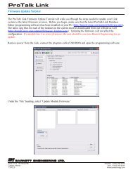
B1474 Product Manual - Barnett Engineering Ltd
B1474 Product Manual - Barnett Engineering Ltd
B1474 Product Manual - Barnett Engineering Ltd

Create successful ePaper yourself
Turn your PDF publications into a flip-book with our unique Google optimized e-Paper software.
RADIO MODEM<br />
<strong>B1474</strong><br />
OPERATION MANUAL<br />
April, 1998<br />
<strong>Manual</strong> Revision 4.1<br />
(for Version 2.1 Hardware)
TABLE OF CONTENTS<br />
FCC REQUIREMENTS . . . . . . . . . . . . . . . . . . . 2<br />
1 INTRODUCTION. . . . . . . . . . . . . . . . . . . . . . 3<br />
2 SPECIFICATIONS . . . . . . . . . . . . . . . . . . . . . 5<br />
3 NOTATION . . . . . . . . . . . . . . . . . . . . . . . . 7<br />
4 OPERATION. . . . . . . . . . . . . . . . . . . . . . . . 8<br />
5 SETUP PROCEDURES . . . . . . . . . . . . . . . . . . . 12<br />
6 INDICATORS . . . . . . . . . . . . . . . . . . . . . . . 16<br />
7 CONFIGURATION . . . . . . . . . . . . . . . . . . . . 17<br />
8 CONNECTIONS. . . . . . . . . . . . . . . . . . . . . . 19<br />
9 BOARD LAYOUT . . . . . . . . . . . . . . . . . . . . . 20<br />
10 WARRANTY STATEMENT . . . . . . . . . . . . . . . . . 21<br />
11 APPENDIX A<br />
OPERATION WITH A GE TRUNKING SYSTEM . . . . . . . 22<br />
<strong>B1474</strong> BARNETT EN GI NEERING LTD. PAGE 1
FCC RE QUIRE MENTS<br />
This equipment generates, uses, and can radiate radio frequency energy and, if not used in<br />
accordance with the instruction manual, may cause interference to radio communications.<br />
It has been tested and found to comply with the limits for a Class A computer device pursuant<br />
to sub-part J of Part 15 of FCC Rules, which are designed to provide reasonable protection<br />
against interference when operated in a commercial environment. Operation of this equipment<br />
in a residential area is likely to cause interference, in which case the user, at his own expense,<br />
will be required to take whatever measures may be required to correct the interference.<br />
This device was tested using a shielded cable connected to the data port. The unit must be<br />
operated using a shielded cable on the data line, with the shield grounded.<br />
<strong>B1474</strong> BARNETT EN GI NEERING LTD. PAGE 2
1 IN TRO DUC TION<br />
The <strong>B1474</strong> Radio Modem provides a reliable method of sending 1200 baud data signals over<br />
radio or cable facilities. Digital information is converted to tone format for transmission over<br />
the communication channel. Received tones are converted back to RS232 digital format.<br />
Hardware handshaking using RTS and CTS signals allows the radio channel to be transparent<br />
to the connected equipment. Warm-up and power down delay times required by the radio do<br />
not affect the data signals. Alternatively, XON/XOFF or data buffering may be used where<br />
hardware handshaking is not available.<br />
The communication channel can be a single pair cable, two pair cable or two-way radio.<br />
Conventional land mobile radio equipment can be used or, if specified at time of order, GE<br />
trunking radios may be used.<br />
Power and audio signals are connected to compression terminals inside the modem; the digital<br />
interface is through a DB-25S connector. The <strong>B1474</strong> requires 12 to 30 VDC, negative ground,<br />
and approximately 60 mA to operate.<br />
Features available in the <strong>B1474</strong> are:<br />
Hardware or Software Hand shak ing<br />
Either RTS and CTS hardware signals or software XON and XOFF characters can be used to<br />
pause the transmitting station while waiting for the radio system to respond. If short data<br />
streams are to be sent, full data buffering may be used to render the radio system transparent.<br />
RTS/CTS De lay<br />
This adjustable delay allows the radio to warm up before data is sent. The delay is active<br />
regardless of whether hardware handshaking or data buffering is used.<br />
PTT<br />
A low going push-to-talk signal is active whenever the modem is transmitting data.<br />
Squelch Detect<br />
If the radio channel is currently being used, the modem will not return the CTS signal until the<br />
channel is available. If XON/XOFF signaling is selected, XOFF will be returned to indicate a<br />
busy channel; then XON will be issued when the channel is free. (This feature may be disabled<br />
using a DIP switch.)<br />
PTT Drop Delay<br />
This adjustable delay prevents squelch tails from disturbing the received data at the other end<br />
of the system.<br />
Level Selection<br />
Transmit levels are adjustable from 0 to -20 dBm. The receive section has selectable gain of<br />
10 dB, if required, to boost low incoming signal levels.<br />
<strong>B1474</strong> BARNETT EN GI NEERING LTD. PAGE 3
In di ca tors<br />
Modem status condition is indicated by front panel LEDs. The LEDs may be disabled to<br />
conserve power.<br />
<strong>B1474</strong> BARNETT EN GI NEERING LTD. PAGE 4
2 SPECIFICATIONS<br />
GENERAL<br />
Transmission Rate: 1200 Baud (Bell 202 signaling) or V.23 if factory installed<br />
Transmission Format: 8 data bits, no par ity, 1 stop bit if modem buffering is selected;<br />
otherwise transparent<br />
Power Requirement: Operates from 12 to 30 VDC. Cur rent drain is 110 mA with the LEDs on,<br />
65 mA with the LEDs off.<br />
Temperature Range: -30<br />
o C to +50 o C<br />
Physical Size: Approx. 10" x 5" x 1", inside a metal enclosure<br />
Radio and Wireline: Compression screw terminals located inside the enclosure<br />
Data Connector: RS232-C compatible, connections available through a DB-25S socket<br />
located on the side of the enclosure<br />
Indicators: Power ON, TXD, RXD, CD, RTS, CTS, BUSY<br />
Receive Audio: Single ended, AC coupled, -30 dBm to 0 dBm<br />
Transmit Audio: Single ended, AC coupled, -20 dBm to 0 dBm<br />
Squelch Detection: Single ended, 1M ohm impedance, DC coupled, detection range<br />
0 to 10 volts, polarity is DIP switch selectable<br />
PTT:<br />
Closure to ground for ac tive, 0.5 A @ 50 volts max.<br />
4 Wire Receive: Balanced, 600 ohm impedance, -30 dBm to 0 dBm (operates full or<br />
half duplex)<br />
4 Wire Transmit: Balanced, 600 ohm impedance, -20 dBm to 0 dBm (operates full or<br />
half duplex)<br />
DIP SWITCH SETTINGS<br />
Transmitter Level: -20 dBm to 0 dBm<br />
Receiver Level: -30 dBm to 0 dBm<br />
Squelch Polarity: Selects high or low going squelch monitor signals.<br />
Carrier Detect Delay: 5 or 50 msec<br />
Assert RTS: Forces RTS on.<br />
RTS/CTS Delay: 20, 35, 50, 100, 200, 300, 500, or 1000 msec. Allows the transmitter<br />
time to reach full power before data is transmitted.<br />
<strong>B1474</strong> BARNETT EN GI NEERING LTD. PAGE 5
PTT Drop De lay:<br />
0, 10, 20, 50, 75, 100 or 250 msec. Keeps transmitter keyed long<br />
enough to ensure squelch tail noise doesn’t interfere with data at the<br />
receiving terminal.<br />
Handshaking: Specifies the type of flow control used.<br />
2/4 Wire: Selects 2 or 4 wire ca ble operation.<br />
LED Control: Disables LEDs to save power.<br />
Equalization:<br />
Full/Half Duplex:<br />
<strong>B1474</strong> BARNETT EN GI NEERING LTD. PAGE 6
3 NOTATION<br />
Throughout this manual, abbreviations will be used. These abbreviations are explained here for<br />
clarity.<br />
CD<br />
COS<br />
CTS<br />
DCE<br />
DTE<br />
FCC<br />
GND<br />
PTT<br />
RFCTS<br />
RTS<br />
SQL<br />
SW1.8<br />
XOFF<br />
XON<br />
Carrier Detect<br />
Carrier Operated Switch<br />
Clear To Send<br />
Data Communications Equipment<br />
Data Terminal Equipment<br />
Federal Communication Commission<br />
Ground<br />
Push To Talk<br />
RF Clear To Send (used in trunking systems only)<br />
Request To Send<br />
Squelch<br />
This signifies a DIP switch. The given example describes the eighth<br />
position on DIP switch number one.<br />
ASCII 13h sent by a receiving station instructing the sending station<br />
to halt any transmission<br />
ASCII 11h sent by a receiving station instructing the sending station<br />
to resume transmission<br />
<strong>B1474</strong> BARNETT EN GI NEERING LTD. PAGE 7
4 OPERATION<br />
The <strong>B1474</strong> operates from 12 to 30 VDC to provide an interface between two computer devices<br />
and the communications channel. In the descriptions below it is assumed that the sending<br />
device uses a DCE configuration.<br />
Four different types of operation may be configured:<br />
Hardware Handshaking<br />
Basic operation and timing using hardware handshaking are as follows:<br />
• The sending device asserts its RTS and waits.<br />
• Upon receiving the RTS, the associated modem performs the following functions:<br />
– checks the channel, if this feature is en abled. If the channel is free, it asserts its PTT to<br />
power up the radio’s trans mit ter.<br />
– presents a mark tone (carrier) onto the channel.<br />
– sets its RTS/CTS de lay timer (from 20 to 1000 msec). RTS/CTS delay must be greater<br />
than the carrier detect de lay at the receiving end.<br />
• The modem at the receiving end senses carrier on the line and asserts its CD. The received<br />
data is muted for 5 or 50 msec to ensure that transients do not affect the received data.<br />
• At the sending end, once the RTS/CTS delay timer has expired, the modem returns a CTS to<br />
the sending computer.<br />
• Data is transmitted; any format may be used.<br />
• Once all the data has been transmitted, the sending computer drops its RTS.<br />
• Upon sensing the dropped RTS, the sending modem does the following:<br />
– drops CTS immediately.<br />
– sets its PTT drop delay timer (0 to 250 msec).<br />
• Once the PTT drop delay timer has expired, the sending modem releases the radio transmit -<br />
ter, turns off the modem carrier and returns to receive mode.<br />
For hardware handshaking, set XON/XOFF signaling off, assert RTS (continuous) off and<br />
buffering off. Set RTS/CTS delay and PTT drop delay as required.<br />
Refer to Figure 1 for a summary of the modem timings.<br />
<strong>B1474</strong> BARNETT EN GI NEERING LTD. PAGE 8
FIGURE 1<br />
MODEM TIMING USING RTS AND CTS<br />
<strong>B1474</strong> BARNETT EN GI NEERING LTD. PAGE 9
Soft ware Handshaking Using XON/XOFF<br />
Basic operation and timing using XON/XOFF software handshaking are as follows:<br />
• The sending computer begins sending data. The format must be 8 data bits, no parity,<br />
1 stop bit.<br />
• Upon detecting data, the sending modem performs the following:<br />
– checks the channel, if this feature is en abled. If the channel is free, it asserts its PTT to<br />
power up the radio’s transmitter. If the channel is busy, it returns XOFF to the sending<br />
computer, which halts the transmission of data. When the channel becomes free, the<br />
modem sends XON to the computer, which resumes sending data. The modem buffers<br />
the data while it continues with the following:<br />
– presents a mark tone (carrier) onto the channel.<br />
– sets its RTS/CTS de lay timer (from 20 to 300 msec). RTS/CTS delay is a misnomer in<br />
this case as software handshaking does not use RTS and CTS signals. It is actually a<br />
buffering time between when the modem starts receiving data from the computer and<br />
when it starts transmitting. This de lay must be greater than the carrier detect delay at<br />
the receiving end.<br />
• The modem at the receiving end senses carrier on the line and asserts its CD. The received<br />
data is muted for 5 or 50 msec to ensure that transients do not affect the received data.<br />
• At the sending end, once the RTS/CTS delay timer has expired, data is transmitted.<br />
– The sending modem’s PTT drop de lay timer is started at the end of the last transmitted<br />
char ac ter.<br />
• Once the PTT drop delay timer has expired, the modem releases the radio transmitter, turns<br />
off the modem carrier and returns to receive mode.<br />
This configuration can buffer 500 msec worth of characters. To prevent internal data buffer<br />
overflow, it is important that the RTS/CTS delay timer be set to a value less than 500 msec and<br />
that the computer respond to XOFF immediately.<br />
For software handshaking, set XON/XOFF signaling on, assert RTS (continuous) off, and<br />
buffering on. Do not connect hardware RTS and CTS. Set RTS/CTS delay and PTT drop delay<br />
as required.<br />
No Hand shak ing, Buffered<br />
Basic operation and timing with data buffering (no handshaking) are as follows:<br />
• The sending computer begins sending data. Data format must be 8 bits, no par ity, 1 stop bit.<br />
• Upon detecting data, the sending modem performs the following:<br />
<strong>B1474</strong> BARNETT EN GI NEERING LTD. PAGE 10
– checks the channel, if this feature is en abled. If the channel is free, it asserts its PTT to<br />
power up the radio’s transmitter. If the channel is busy, it buffers the received data until<br />
the channel becomes free.<br />
– presents MARK tone (carrier) onto the channel.<br />
– sets its RTS/CTS de lay timer (from 20 to 300 msec). RTS/CTS delay is a misnomer in<br />
this case as handshaking is not used. It is actually a buffering time between when the<br />
modem starts receiving data from the computer and when it starts transmitting.<br />
RTS/CTS de lay must be greater than the carrier detect de lay at the receiving end.<br />
• The modem at the receiving end senses carrier on the line and asserts its CD. The received<br />
data is muted for 5 or 50 msec to ensure that transients do not affect the received data.<br />
• At the sending end, once the RTS/CTS delay timer has expired, data is transmitted.<br />
• Receipt of any character from the sending device, or transmission of any buffered char ac t er,<br />
restarts the sending modem’s PTT drop delay timer (from 0 to 250 msec).<br />
• Once the PTT drop delay timer has expired, the modem releases the radio transmitter and<br />
returns to receive mode.<br />
This configuration can buffer 500 msec worth of characters. To prevent internal data buffer<br />
overflow, it is important that the radio system will be available within 500 msec (RTS/CTS<br />
delay plus maximum channel busy time) or the maximum amount of buffered data be less than<br />
50 characters.<br />
For no handshaking, buffered operation, set XON/XOFF signaling off, assert RTS<br />
(continuous) off, and buffering on. Do not connect the hardware RTS and CTS. Set<br />
RTS/CTS delay and PTT drop delay as required.<br />
No Hand shak ing, Non-Buffered<br />
Basic operation and timing with no handshaking, no data buffering are as follows:<br />
• RTS is al ways asserted. Do not connect the hardware RTS.<br />
• PTT is always asserted, i.e. the ra dio’s carrier is always on. There is no RTS/CTS delay or<br />
PTT drop delay.<br />
• Data generated by the sending device is passed directly through the modem without hand -<br />
shaking, buffering or time de lays. Data may be any format.<br />
For no handshaking, non-buffered operation, set XON/XOFF signaling off, assert RTS<br />
(continuous) on, and buffering off. Do not connect the hardware RTS and CTS, and do not set<br />
RTS/CTS or PTT drop delays.<br />
<strong>B1474</strong> BARNETT EN GI NEERING LTD. PAGE 11
5 SETUP PROCEDURES<br />
The semiconductors can be damaged by static discharge. Proper handling procedures must be followed.<br />
Do not touch any of the devices inside the modem, and work only in a static free, clean, and dry<br />
environment.<br />
(1) Remove The Top Cover<br />
Remove the two center screws on the top cover of the modem to release it from the base. Pull<br />
straight up on the cover to expose connections and internal DIP switches.<br />
(2) CON NEC TIONS<br />
Line In ter face<br />
Connect the audio wires in accordance with the configurations below:<br />
4 wire cable: Connect the two transmit wires into pins 4 and 5 of P1. The receive wires con -<br />
nect into pins 7 and 8 of P1. SW3.3 and SW3.4 must be OFF.<br />
2 wire cable: Connect the two wires into pins 4 and 5 of P1. Ensure that SW3.3 and SW3.4 are<br />
ON.<br />
Radio<br />
If the radio is equipped with a 600 ohm balanced interface, connect the transmit and receive<br />
audio lines as shown above for a cable interface.<br />
For a single-ended radio interface, connect P1-3 to the transmit line of the radio and P1-6 to the<br />
receive line. Connecting the receive input to an unsquelched source in the radio will result in<br />
extraneous characters at the data port, unless the squelch detector is set properly.<br />
PTT:<br />
Squelch:<br />
The <strong>B1474</strong> provides an open collector driver for the radio PTT at P1-10.<br />
The radio’s receive carrier operated switch (COS) can be monitored to detect<br />
when the radio is receiving a signal by connecting the COS line to P1-7. This sig -<br />
nal is used to inhibit transmissions over a busy channel.<br />
The in put is capable of monitoring a level from 0 to 10 VDC.<br />
See “Squelch Polarity” under DIP switch settings to set the COS polarity and<br />
level, or to disable this fea ture.<br />
Dig i tal Connection<br />
If using the Option 002 trunking software, connect the radio’s RFCTS into the<br />
squelch input.<br />
A DB-25S socket on the side of the unit is used to interface with the computer equipment.<br />
The RS232 interface provides a DCE interface using the following signals:<br />
<strong>B1474</strong> BARNETT EN GI NEERING LTD. PAGE 12
GND (Chassis) Pin 1<br />
TXD Pin 2<br />
RXD Pin 3<br />
RTS Pin 4 (connect only if using hardware handshaking)<br />
CTS Pin 5 (connect only if using hardware handshaking)<br />
GND (Signal) Pin 7<br />
CD Pin 8<br />
The cable and housing on the DB-25S socket must be shielded to conform to FCC, part 15-J/A standards<br />
for emissions. Using a non-shielded cable may result in undesirable radio interference.<br />
(3) DIP SWITCH SET TINGS<br />
The following section describes the function of each DIP switch on the modem. The settings are<br />
summarized in a table in Section 7 - Configuration.<br />
LED Con trol<br />
The LED indicators may be disabled to conserve power. Set SW1.1 OFF to disable the LEDs.<br />
RTS/CTS De lay<br />
When the sending device requests transmission, a preset delay is inserted before the modem<br />
transmits. This delay allows the two-way radio to warm up, or, on a cable system, allows the<br />
tones to settle on the channel before data transmission begins. When hardware handshaking is<br />
used, the modem pauses the sending device by delaying return of the CTS signal. When<br />
XON/OFF or no handshaking are used, the RTS/CTS delay specifies the amount of data which<br />
will be buffered. Set DIP switches SW1.2, SW1.3, and SW1.4 for the desired delay, from 20 to<br />
1000 msec, as specified in Section 7 - Configuration.<br />
PTT Drop Delay<br />
When transmission is no longer requested by the sending computer, a selectable delay is<br />
inserted before the PTT on the radio is released. This delay prevents the squelch tail at the<br />
receiving radio from interfering with the data. Set DIP switches SW1.5, SW1.6, and SW1.7 for<br />
the desired drop delay, between 0 and 500 msec, as specified in Section 7 - Configuration.<br />
XON / XOFF Con trols<br />
SW1.8 controls whether the modem will send XON and XOFF to the sending computer when<br />
the radio channel is busy (software handshaking). If the sending computer does not<br />
understand these characters, the switch must be OFF.<br />
Squelch Polarity<br />
If the modem is connected to a radio, the channel can be monitored for RF carrier. SW1.9 is<br />
changed depending upon the polarity of the carrier operated switch (COS) signal. If the COS<br />
goes high when carrier is present, and low when the channel is free, set SW1.9 OFF. If the<br />
opposite occurs, set SW1.9 ON. While the channel is busy, the modem will wait, sending only<br />
when the channel is clear.<br />
<strong>B1474</strong> BARNETT EN GI NEERING LTD. PAGE 13
Adjust R12 so that the modem waits when the channel is busy, and transmits when the channel<br />
is free. When the BUSY light is ON, the modem is waiting for the channel.<br />
To disable this feature, leave P1-9 unconnected and SW1.9 OFF.<br />
If Option 002 trunking software is used, set SW1.9 according to the polarity of the RFCTS signal<br />
connected into P1-9. Set SW1.9 and R12 so that the data is only transmitted once the channel<br />
has been assigned.<br />
Send/Receive<br />
When using the Option 002 trunking software and data buffering, use SW1.10 to configure the<br />
modem for send or receive mode. Normally, all modems within a system should be set for send<br />
mode, meaning that they will key the trunking radio and wait for RFCTS when data<br />
transmission is required. Setting SW1.10 ON sets the modem into receive mode. In this mode,<br />
the modem will only hit PTT if the channel has already been established by another modem.<br />
Having one modem in send mode and another in receive mode will ensure that both modems<br />
do not try to acquire the channel at the same time.<br />
Set SW1.10 to OFF if using hardware handshaking or conventional radios.<br />
Trans mit Level<br />
To adjust the output level of the modem to between 0 and -20 dBm, set DIP switches SW2.1,<br />
SW2.2 and SW2.3 as specified Section 7 - Configuration.<br />
The output levels given are referenced into 600 ohms. Should the output be driven into a high<br />
impedance, the level will be approximately 6 dB higher than expected.<br />
If a high level is required into a single-ended input, connect P1-5 to ground, and use P1-4 to<br />
drive the input.<br />
Re ceive Gain<br />
DIP switch SW2.5 is used to boost the received signal. To insert 10 dB of gain, turn SW2.5 ON.<br />
This will amplify all incoming signals (including all valid data tones).<br />
Equalization (Mode 1)<br />
To enable the internal amplitude equalizer, set SW2.6 ON. To leave this feature disabled, set<br />
SW2.6 OFF. Use equalization when there is a large discrepancy in levels between the two tones.<br />
Car rier De tect Delay (Mode 2)<br />
When the receiving modem detects carrier, it mutes the RXD line for a short time to ensure that<br />
transients do not affect the received data. Set SW2.7 OFF to delay the received data for 5 msec,<br />
ON to delay the received data for 50 msec. Carrier detect delay should be less than the<br />
RTS/CTS delay at the sending end.<br />
Full/Half Du plex (Mode 3)<br />
<strong>B1474</strong> BARNETT EN GI NEERING LTD. PAGE 14
To operate full duplex, leave SW2.8 OFF. To operate half duplex, set switch SW2.8 ON. If a<br />
2 wire circuit is used, the modem will only operate half duplex.<br />
RTS Con trol<br />
SW3.1, when ON, will assert RTS continuously. This causes PTT to be asserted and transmit<br />
tones to be generated. The switch should be on for a no handshaking, non-buffered<br />
configuration. The continuous RTS is also useful for testing purposes.<br />
Buffer<br />
If hardware handshaking is desired, connect the RTS and CTS signals to the DB-25S connector<br />
and set SW3.2 OFF. If XON/XOFF control (software handshaking) or no handshaking with full<br />
buffering is desired, set SW3.2 ON and remove connections from the RTS and CTS positions in<br />
the DB-25S connector.<br />
2/4 Wire<br />
Set SW3.3 and SW3.4 OFF if 4 wire communications are used. Set SW3.3 and SW3.4 ON if<br />
2 wire communications are used. If a 2 wire circuit is used, the modem will only operate half<br />
duplex.<br />
(4) Replace The Top Cover<br />
Place the top cover back onto the base and tighten the two center screws.<br />
(5) Ap ply Volt age<br />
Apply the proper voltage to the unit. If the LEDs are enabled, the run lamp will illuminate,<br />
indicating that power is available at the modem.<br />
<strong>B1474</strong> BARNETT EN GI NEERING LTD. PAGE 15
6 INDICATORS<br />
The LED indicators on the front case are used to indicate modem status:<br />
RUN<br />
BUSY<br />
RTS<br />
CTS<br />
CD<br />
RXD<br />
TXD<br />
Power is on the modem.<br />
The modem is waiting to transmit but is held back by the squelch detector.<br />
Request To Send from the computer is present or characters have been<br />
received into the buffer.<br />
Clear To Send is active.<br />
Carrier is detected on the incoming channel.<br />
On when a mark is received and off when a space is received.<br />
On when a mark is transmitted.<br />
The LEDs may be disabled to conserve power by setting SW1.1 off.<br />
<strong>B1474</strong> BARNETT EN GI NEERING LTD. PAGE 16
7 CONFIGURATION<br />
SWITCH 1<br />
SWITCH 2<br />
1<br />
X<br />
2<br />
X<br />
X<br />
X<br />
X<br />
5<br />
X<br />
X<br />
X<br />
8<br />
X<br />
9<br />
X<br />
LED CONTROL<br />
LEDS OFF<br />
LEDS ON<br />
RTS/CTS DELAY<br />
3 4 msec<br />
20<br />
35<br />
X 50<br />
X 100<br />
X 200<br />
X 300<br />
X X 500<br />
X X 1000<br />
PTT DROP DELAY<br />
6 7 msec<br />
0<br />
10<br />
X 20<br />
X 50<br />
X 75<br />
X 100<br />
X X 250<br />
XON/XOFF<br />
NO XON/XOFF<br />
USE XON/XOFF<br />
SQUELCH POLARITY<br />
LOW = CHANNEL FREE<br />
HIGH = CHANNEL FREE<br />
TX LEVEL (INTO 600 OHMS)<br />
1 2 3 Radio (dBm) Bal -<br />
-4<br />
0<br />
X -6<br />
-2<br />
X -8<br />
-4<br />
X X -10<br />
-6<br />
X -12<br />
-8<br />
X X -14<br />
-10<br />
X X -20<br />
-16<br />
X X X -24<br />
-20<br />
5 dB<br />
0<br />
X 10<br />
6<br />
X<br />
7<br />
X<br />
8<br />
X<br />
MODE 3 (DUPLEX)<br />
FULL DUPLEX<br />
HALF DUPLEX<br />
RX GAIN<br />
MODE 1 (EQUALIZATION)<br />
NO RECEIVE EQUALIZATION<br />
RECEIVE EQUALIZATION<br />
MODE 2 (CD DELAY)<br />
CD DELAY = 5 msec<br />
CD DELAY = 50 msec<br />
SEND/RECEIVE (TRUNKING ONLY)<br />
10<br />
X<br />
PTT RE GARD LESS OF RFCTS<br />
PTT ONLY WITH RFCTS<br />
<strong>B1474</strong> BARNETT EN GI NEERING LTD. PAGE 17
SWITCH 3<br />
1<br />
X<br />
2<br />
X<br />
RTS ON<br />
EXTERNAL RTS<br />
RTS ON AT ALL TIMES<br />
BUFFER<br />
USE RTS/CTS CONTROL<br />
USE BUFFER<br />
3<br />
X<br />
4<br />
X<br />
RTS ON<br />
4 WIRE CA BLE<br />
2 WIRE CA BLE<br />
<strong>B1474</strong> BARNETT EN GI NEERING LTD. PAGE 18
8 CON NEC TIONS<br />
P1<br />
AUDIO<br />
PIN SYMBOL DESCRIPTION<br />
1<br />
+V<br />
INPUT VOLTAGE<br />
2<br />
3<br />
4<br />
5<br />
6<br />
7<br />
8<br />
9<br />
10<br />
GND<br />
GROUND<br />
TX RADIO<br />
TX WL<br />
TX WL<br />
RX RADIO<br />
RX WL<br />
RX WL<br />
SQL<br />
PTT<br />
}<br />
}<br />
TRANSMIT OUTPUT, SINGLE ENDED<br />
TRANSMIT OUTPUT, BALANCED<br />
RECEIVE INPUT, SINGLE ENDED<br />
RECEIVE INPUT, BALANCED<br />
SQUELCH DETECTOR INPUT<br />
PUSH TO TALK OUTPUT<br />
P3<br />
DIGITAL<br />
PIN<br />
1<br />
2<br />
3<br />
4<br />
5<br />
7<br />
8<br />
SYMBOL<br />
GND<br />
TXD<br />
RXD<br />
RTS<br />
CTS<br />
SIG GND<br />
CD<br />
CHASSIS GROUND<br />
TRANSMIT DATA<br />
RECEIVE DATA<br />
REQUEST TO SEND<br />
CLEAR TO SEND<br />
SIGNAL GROUND<br />
CARRIER DETECT<br />
<strong>B1474</strong> BARNETT EN GI NEERING LTD. PAGE 19
9 BOARD LAYOUT<br />
<strong>B1474</strong> BARNETT EN GI NEERING LTD. PAGE 20
<strong>Barnett</strong> En gi neering Prod uct War ranty<br />
WARRANTY STATEMENT<br />
<strong>Barnett</strong> <strong>Engineering</strong> <strong>Ltd</strong>. warrants that all equipment supplied shall be free from defects in<br />
material or workmanship at the time of delivery. Such warranty shall extend from the time of<br />
delivery for a period of one year. Buyer must provide written notice to <strong>Barnett</strong> <strong>Engineering</strong><br />
<strong>Ltd</strong>. within this prescribed warranty period for any defect. If the defect is not the result of<br />
improper usage, service, maintenance, or installation and the equipment has not been otherwise<br />
damaged or modified after delivery, <strong>Barnett</strong> <strong>Engineering</strong> <strong>Ltd</strong>. shall either replace or repair the<br />
defective part or parts of equipment or replace the equipment or refund the purchase price at<br />
<strong>Barnett</strong> <strong>Engineering</strong> <strong>Ltd</strong>.’s option after return of such equipment by the buyer to <strong>Barnett</strong><br />
<strong>Engineering</strong> <strong>Ltd</strong>. Shipment to <strong>Barnett</strong> <strong>Engineering</strong> <strong>Ltd</strong>.’s facility shall be borne on account of<br />
the buyer.<br />
(1) Consequential Damages<br />
<strong>Barnett</strong> <strong>Engineering</strong> <strong>Ltd</strong>. shall not be liable for any incidental or consequential damages<br />
incurred as a result of any defect in any equipment sold hereunder and <strong>Barnett</strong> <strong>Engineering</strong><br />
<strong>Ltd</strong>.’s liability is specifically limited to its obligation described herein to repair or replace a<br />
defective part or parts covered by this warranty.<br />
(2) Exclusive Warranty<br />
The warranty set forth herein is the only warranty, oral or written, made by <strong>Barnett</strong> <strong>Engineering</strong><br />
<strong>Ltd</strong>. and is in lieu of and replaces all other warranties, expressed or implied, including the<br />
warranty of merchantability and the warranty of fitness for particular purpose.<br />
<strong>B1474</strong> BARNETT EN GI NEERING LTD. PAGE 21
11 APPENDIX A - OPERATION WITH A GE MARC V TRUNKING SYSTEM<br />
When ordered with the Option 002 trunking software, the <strong>B1474</strong> will handle the special timing<br />
and control requirements of a GE Marc V trunking system. The following sections describe the<br />
connections to a trunking radio, and the slightly different operation of the radio modem.<br />
CON NEC TIONS<br />
The modem connects into the Marc V system the same as it would to a conventional radio, as<br />
described in section 5, using the PTT, RX data and TX data pins. The only difference is that the<br />
squelch monitor is tied to RFCTS within the radio to determine when the channel is assigned.<br />
To ensure that these connections are made correctly and the proper signals are supplied to each<br />
unit, order the Option 001 interface cable from <strong>Barnett</strong> <strong>Engineering</strong> <strong>Ltd</strong>. Otherwise, refer to the<br />
manual for the Ericsson GE radio to determine the correct interface points.<br />
OPERATION<br />
The trunking modem operates with some slight timing differences from the conventional<br />
modem.<br />
Hardware Handshaking<br />
The sequence followed in obtaining a trunked channel and transmitting the sending computer’s<br />
data using hardware (RTS/CTS) handshaking is described below. Refer to Figure 2 for an<br />
illustration of the timing relationships.<br />
1. The sending computer asserts its Request to Send (RTS), causing the modem to<br />
key the radio and wait for a channel to be assigned.<br />
2. When the channel is assigned, the trunking radio returns RF Clear to Send<br />
(RFCTS) to the modem. The signal is connected to the SQUELCH input on the<br />
modem.<br />
3. The modem produces tones onto the channel and waits the specified RTS/CTS<br />
delay. This delay is a minimum of 5 msec to ensure that all tones have stabilized<br />
before any data is sent.<br />
4. When the RTS/CTS delay has expired, CTS is returned to the sending computer<br />
and the transmission of data begins. When all of the data has been transferred,<br />
the sending computer drops its RTS signal, causing the modem to drop its CTS<br />
signal.<br />
5. The modem holds the radio’s Push To Talk (PTT) on the radio until the PTT<br />
Drop Delay has expired. The channel assignment will not be lost immediately on<br />
releasing PTT, so the receiving computer can use the same channel to respond.<br />
The receiving computer receives a Carrier Detect (CD) followed by the data some interval later<br />
.<br />
<strong>B1474</strong> BARNETT EN GI NEERING LTD. PAGE 22
FIGURE 2 MODEM TIMING FOR A GE MARC V<br />
TRUNKING SYSTEM USING RTS/CTS HANDSHAKING<br />
<strong>B1474</strong> BARNETT EN GI NEERING LTD. PAGE 23
Soft ware Handshaking Using XON/XOFF<br />
Basic operation and timing using XON/XOFF software handshaking in a trunking system is as<br />
follows:<br />
• The sending computer begins sending data. The format must be 8 data bits, no parity,<br />
1 stop bit.<br />
• Upon detecting data, the sending modem performs the following:<br />
– checks the channel. If RFCTS has already been assigned (the channel is available), it as -<br />
serts its PTT to power up the radio’s transmitter. If the channel has not been assigned<br />
yet, it sends XOFF to the sending computer and asserts PTT to obtain the channel.<br />
When the channel gets assigned, it sends XON to the computer and continues.<br />
– presents tones onto the channel.<br />
– sets its RTS/CTS de lay timer.<br />
• The receiving modem senses carrier on the line and asserts its CD. The received data is<br />
muted for 5 or 50 msec to ensure that transients do not affect the received data.<br />
• After the RTS/CTS de lay timer has expired, data is transmitted.<br />
• Whenever the modem receives a character from the sending device or transmits any buf -<br />
fered character, it restarts the PTT drop delay timer.<br />
• Once the modem stops receiving characters and the PTT drop delay timer has expired, the<br />
modem releases the radio transmitter and returns to receive mode.<br />
This configuration can buffer 500 msec worth of characters. To prevent internal data buffer<br />
overflow, it is important that the RTS/CTS delay timer be set to a value less than 500 msec and<br />
that the computer respond immediately to an XOFF command.<br />
<strong>B1474</strong> BARNETT EN GI NEERING LTD. PAGE 24
No Handshaking<br />
Basic operation and timing with data buffering (no handshaking) in a trunking system is as<br />
follows:<br />
• The sending computer begins sending data. Data format must be 8 bits, no par ity, 1 stop bit.<br />
• Upon receiving data, the modem performs the following:<br />
– checks the channel for RFCTS - if the channel has been assigned already, it asserts<br />
its PTT to power up the radio’s transmitter. If the channel is busy, it asserts PTT to ob -<br />
tain the channel and buffers the received data until the channel becomes assigned.<br />
– presents tones onto the channel.<br />
– sets its RTS/CTS de lay timer.<br />
• The receiving modem senses carrier on the line and asserts its CD. The received data is<br />
muted for 5 or 50 msec to ensure that transients do not affect the received data.<br />
• After the RTS/CTS de lay timer has expired, data is transmitted.<br />
• Receipt of any character or transmission of any buffered character restarts the modem’s PTT<br />
drop de lay timer.<br />
• Once the modem stops receiving characters and the PTT drop delay timer expires, the mo -<br />
dem releases the radio transmitter and returns to receive mode.<br />
This configuration can buffer 500 msec worth of characters. To prevent internal data buffer<br />
overflow, it is important that the radio system will be available within 500 msec (RTS/CTS<br />
delay plus maximum channel busy time) or the maximum amount of buffered data is less than<br />
50 characters.<br />
<strong>B1474</strong> BARNETT EN GI NEERING LTD. PAGE 25