ProTalk Expander Manual Version 1.00 - Barnett Engineering Ltd
ProTalk Expander Manual Version 1.00 - Barnett Engineering Ltd
ProTalk Expander Manual Version 1.00 - Barnett Engineering Ltd

You also want an ePaper? Increase the reach of your titles
YUMPU automatically turns print PDFs into web optimized ePapers that Google loves.
<strong>ProTalk</strong> <strong>Expander</strong><br />
Operating <strong>Manual</strong><br />
Model B1292<br />
February, 2006<br />
Rev. <strong>1.00</strong><br />
BARNETT ENGINEERING LTD.<br />
215, 7710 5 th St. S.E. Phone: (403) 255-9544<br />
Calgary, Alberta, Canada Fax: (403) 259-2343<br />
T2H 2L9<br />
www.barnett-engg.com<br />
e-mail: sales@barnett-engg.com
TABLE OF CONTENTS<br />
1. Introduction...........................................................................1<br />
2. Installation .............................................................................2<br />
2.1 Wiring Diagram ................................................................3<br />
3. Operations .............................................................................4<br />
4. Programming (B1225 Mode) .............................................5<br />
4.1 Overview...........................................................................5<br />
4.2 Programming Flowchart ...................................................6<br />
4.3 Programming Examples....................................................6<br />
5. Programming (B1290 Mode) .............................................9<br />
5.1 Overview...........................................................................9<br />
5.2 Programming Flowchart .................................................10<br />
5.3 Programming Examples..................................................11<br />
6. Specifications .....................................................................13<br />
7. Warranty Statement...........................................................14<br />
8. Appendix A - Mounting Details.......................................15
INTRODUCTION PAGE 1<br />
1. INTRODUCTION<br />
The B1292 <strong>ProTalk</strong> <strong>Expander</strong> unit provides an additional 8 digital inputs<br />
and 4 relay outputs to either the B1225 or B1290 Alarm Reporting Units.<br />
Up to 7 expanders can be connected to the master unit for a total of 64<br />
inputs and 32 outputs.<br />
The B1292 is fully compatible with previous expanders and can be<br />
intermixed with older units on existing systems. It is housed in a compact<br />
3.5’ x 5.5’ metal case and features LED indicators to display alarm and<br />
relay status information.<br />
A coaxial communications cable connects the master unit to the first<br />
expander and each additional expander in a daisy-chain manner. The<br />
master unit controls communications on the cable.
PAGE 2<br />
INSTALLATION<br />
2. INSTALLATION<br />
The B1292 features plug-in terminal blocks for all alarm and relay<br />
connections.<br />
A coax cable (supplied) connected to the EXP connector is used to<br />
establish serial communications with the master unit. Additional<br />
expanders are connected in a daisy chain configuration. <strong>Expander</strong>s must<br />
be powered up before or at the same time as the main <strong>ProTalk</strong> ARU.<br />
Alarm Connector<br />
1 Alarm 1<br />
2 Alarm 1<br />
3 Alarm 1<br />
4 Alarm 1<br />
5 Alarm 1<br />
6 Alarm 1<br />
7 Alarm 1<br />
8 Alarm 1<br />
9 Ground<br />
10 Ground<br />
11 Ground<br />
12 Power +11.5 to +28 VDC<br />
Relay Connector<br />
1 Relay 1 NC<br />
2 Relay 1 Common<br />
3 Relay 1 NO<br />
4 Relay 2 NC<br />
5 Relay 2 Common<br />
6 Relay 2 NO<br />
7 Relay 3 NC<br />
8 Relay 3 Common<br />
9 Relay 3 NO<br />
10 Relay 4 NC<br />
11 Relay 4 Common<br />
12 Relay 4 NO<br />
<strong>Expander</strong> Communications (2)<br />
Inner Signal<br />
Outer Ground<br />
There are two connectors for expander communications (EXP); both<br />
connectors operate in the same way. It does not matter which connector is<br />
used for attaching the previous or next device in the system.<br />
Do not apply power to the EXP connector.
INSTALLATION PAGE 3<br />
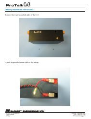
3.1 WIRING DIAGRAM<br />
Figure 1 <strong>ProTalk</strong> <strong>Expander</strong> Wiring Connections
PAGE 4<br />
OPERATIONS<br />
3. OPERATIONS<br />
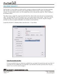
The front panel of the B1292 is shown in Figure 2. The front panel<br />
indicators assist in verifying the correct operation of the unit. Detailed<br />
information on the overall operation of the alarm system that the expander<br />
is being used with is contained in the manual for the main reporting unit.<br />
ALARMS<br />
EXP ID<br />
ALARMS<br />
2 4 5<br />
6<br />
7<br />
8<br />
STATUS<br />
Pw r<br />
Tx<br />
Rx<br />
RELAYS<br />
2 4<br />
EXP<br />
RELAYS<br />
EXP<br />
Figure 2 <strong>ProTalk</strong> <strong>Expander</strong> Front Panel<br />
Alarm LEDs<br />
Relay LEDs<br />
PWR LED<br />
Tx LED<br />
unit.<br />
Rx LED<br />
bus.<br />
The Alarm LED is on when the associated input is in the alarm<br />
state. When connected to a B1290, unacknowledged alarms<br />
will be flashing and any that have been acknowledged will be<br />
on solid.<br />
The Relay LEDs light whenever the associated relay is on.<br />
The PWR LED indicates that power has been applied to the<br />
unit as well as the operational mode that it is configured for.<br />
Solid indicates that the unit is in B1225 mode, flashing<br />
indicates B1290 mode.<br />
The Tx LED lights when the B1292 is sending to the main<br />
The Rx LED lights when a message are present on the serial
PROGRAMMING (B1225 MODE) PAGE 5<br />
4. PROGRAMMING (B1225 MODE)<br />
4.1 OVERVIEW<br />
Each expander has a unique ID number (1-7) set on the rotary switch. This<br />
ID number is used during programming to select the desired unit. If the<br />
expander ID is changed, the system must have power removed and then<br />
reapplied before the new address is recognized.<br />
The operational mode of the B1292 will automatically be set when the unit<br />
is programmed. A solid PWR LED indicates B1225 mode.<br />
Before programming the expander the “Number of <strong>Expander</strong>s” and<br />
“<strong>Expander</strong> Site Voice” must be set on the B1225. The expander is<br />
programmed through the B1225 with the handset.<br />
At the “Enter Program Code” prompt, the different functions of the<br />
expander can be selected by entering their program code. When an<br />
individual expander is accessed, its configuration is read into the B1225<br />
over the expander serial connection. At this point, if necessary, the<br />
operational mode of the expander is automatically set B1225 mode. When<br />
the program phone is hung up the new configuration is written back to the<br />
expander and stored in non-volatile FLASH memory.<br />
Although expanders are shipped with a “default” configuration, the Alarm<br />
Voices must be programmed.<br />
A description of the programming procedure for a B1225 expander is<br />
given below. Use these codes in conjunction with the programming<br />
manual for the B1225. N is the expander ID number of the unit being<br />
programmed.
PAGE 6<br />
PROGRAMMING (B1225 MODE)<br />
4.2 PROGRAMMING FLOWCHART (B1225 MODE)<br />
N = expander ID number; where X appears, user data is entered.<br />
#N1** Voices<br />
2** Record<br />
** Next<br />
#N4** Alarm On/Off DTMF X** Alarm Number<br />
X** Change<br />
#** Clear<br />
** Next<br />
#N5** Alarm Debounce X** Change<br />
** Next<br />
#N6** Alarm Format 0** NO<br />
1** NC<br />
#N8** Relay On/Off DTMF X** Change<br />
#** Clear<br />
** Next<br />
#N9** Relay Format X** Change<br />
** Next<br />
Relay On Timer<br />
X** Change<br />
** Next<br />
4.3 PROGRAMMING EXAMPLES<br />
#N1** VOICES<br />
The site identifier and each of the 8 alarm inputs are programmed for the<br />
expander in this section. The alarm messages are identified as N.1 to N.8<br />
instead of 1 to 8 in the master B1225.<br />
Example: You want to program the site identifier in the first expander to<br />
say “Delta Compressor”<br />
ARU: ENTER PROGRAM CODE<br />
YOU: #11 (selecting voice message)<br />
ARU: EXPANDER1 SITE IS …<br />
YOU: 2 (selecting change)<br />
ARU: BEEP - (record light comes on)<br />
YOU: (speaking) DELTA COMPRESSOR<br />
ARU: EXPANDER 1 SITE IS DELTA COMPRESSOR<br />
YOU: <br />
ARU: ALARM NUMBER 1 point 1 IS … (on to the alarm messages)
PROGRAMMING (B1225 MODE) PAGE 7<br />
#N4** ALARM ON/OFF DTMF<br />
The DTMF on and off strings will be programmed for the expander<br />
specified. As in the voice message programming section, the expander and<br />
alarms will be announced as N point 1 to N point 8<br />
Example: You want to program the second input in expander 1 to have a<br />
DTMF ON code of 123 and an off code of 456.<br />
ARU: ENTER PROGRAM CODE<br />
YOU: #14<br />
ARU: ENTER ALARM NUMBER<br />
YOU: 2<br />
ARU: ALARM NUMBER 1 point 2 DTMF ON CODE IS …<br />
YOU: 123<br />
ARU: ALARM NUMBER 1 point 2 DTMF ON CODE IS 123<br />
YOU: <br />
ARU: DTMF OFF CODE IS …<br />
YOU: 456<br />
ARU: DTMF OFF CODE IS 456<br />
YOU: <br />
ARU: ENTER ALARM NUMBER<br />
#N5** ALARM DEBOUNCE<br />
Alarm delay time (debounce time) can be set for each expander and must<br />
be between 0.1 and 9.9 seconds. One debounce time is used for all of the<br />
inputs on a particular expander. Each expander may have a different time.<br />
The input must remain active for this period of time in order for it to be<br />
considered a change of state.<br />
Example: The debounce time for expander 2 is to be set at 3 seconds.<br />
ARU: ENTER PROGRAM CODE<br />
YOU: #25<br />
ARU: EXPANDER 2 ALARM DELAY IS 0.5 SECONDS<br />
YOU: 30<br />
ARU: EXPANDER 2 ALARM DELAY IS 3.0 SECONDS<br />
YOU: <br />
#n6** ALARM FORMAT<br />
Each alarm input on an expander can be programmed to be Normally<br />
Open (N.O. – requiring a ground closure to become active) or Normally<br />
Closed (N.C. - requiring a release from ground to become active). The<br />
ALARM FORMAT must be a 0 for N.O. contacts or a 1 for N.C. contacts.<br />
Example: The inputs for expander two are to be set for normally closed<br />
inputs.<br />
ARU: ENTER PROGRAM CODE<br />
YOU: #26<br />
ARU: EXPANDER 2 ALARM FORMAT IS 0<br />
YOU: 1<br />
ARU: EXPANDER 2 ALARM FORMAT IS 1<br />
YOU:
PAGE 8<br />
PROGRAMMING (B1225 MODE)<br />
#N8** RELAY ON/OFF DTMF<br />
The four relays on each expander can have DTMF on and off codes<br />
programmed for remote control. They will be announced as relay numbers<br />
X.1 to X.4 . The master will interpret DTMF strings from the radio system<br />
as ON or OFF controls for the relays. Each string may be up to 8<br />
characters.<br />
Example: The control codes for the output relays in expander one are to be<br />
programmed. The first relay will have an ON code of 789 and an OFF<br />
code of 321<br />
ARU: ENTER PROGRAM CODE<br />
YOU: #18<br />
ARU: RELAY NUMBER 1 point 1 DTMF ON CODE IS EMPTY<br />
YOU: 789<br />
ARU: RELAY NUMBER 1 point 1 DTMF ON CODE IS 789<br />
YOU: <br />
ARU: RELAY NUMBER 1 point 1 DTMF OFF CODE IS EMPTY<br />
YOU: 321<br />
ARU: RELAY NUMBER 1 point 1 DTMF OFF CODE IS 321<br />
YOU: <br />
#N9** RELAY FORMAT<br />
This will specify the type of relays being used for each expander. The<br />
relays will be announced as N.1 to N.4. Each relay may be of a different<br />
format. (0=standard, 1=latched, 2=timed).<br />
: Note: Relay Format 1 (Latched) is not supported in the B1292 and will<br />
default to “standard” if selected.<br />
Example: Relay one in expander one is to be set as a timed relay.<br />
ARU: ENTER PROGRAM CODE<br />
YOU: #19<br />
ARU: RELAY NUMBER 1 point 1 FORMAT IS ZERO<br />
YOU: 2<br />
ARU: RELAY NUMBER 1 point 1 FORMAT IS TWO<br />
YOU:
PROGRAMMING (B1290 MODE) PAGE 9<br />
5. PROGRAMMING (B1290 MODE)<br />
5.1 OVERVIEW<br />
Each expander is assigned a unique ID number (1-7) using a rotary switch.<br />
This ID number is used during programming to select the desired unit.<br />
If the expander ID is changed, the system must have power removed and<br />
then reapplied before the new address is recognized.<br />
The operational mode of the B1292 will automatically be set when the unit<br />
is programmed. A flashing PWR LED indicates B1290 mode.<br />
Before programming the expander the “Number of <strong>Expander</strong>s” and<br />
“<strong>Expander</strong> Site Voice” must be set on the B1290.<br />
<strong>Expander</strong>s connected to a B1290 may be programmed through the B1290<br />
handset, remotely or using PC Configuration Software.<br />
All the expander’s programmed parameters, aside from the voice<br />
messages, are stored in the main <strong>ProTalk</strong> Plus and are downloaded on<br />
power-up. The B1292 will switch to B1290 Mode when this download is<br />
complete.<br />
The following program codes are valid for the B1292 expander when in<br />
B1290 mode. Use these codes in conjunction with the programming<br />
manual for the B1290. N is the expander ID number of the unit being<br />
programmed.
PAGE 10<br />
PROGRAMMING (B1290 MODE)<br />
5.2 PROGRAMMING FLOWCHART (B1290 MODE)<br />
N = expander ID number, where X appears, user data is entered.<br />
N1** Voices 1** Alarms<br />
2** Record<br />
3** Erase<br />
** Next<br />
#** Quit<br />
2** Relays<br />
2** Record<br />
3** Erase<br />
** Next<br />
#** Quit<br />
#31** Erase all<br />
N3** DTMF 3** Relay On/Off<br />
X** Change<br />
#** Clear<br />
** Next<br />
4** Alarm On/Off<br />
X** Change<br />
#** Clear<br />
** Next<br />
5** Remote Alarm<br />
X** Change<br />
#** Clear<br />
** Next<br />
N5** I/O Configuration 1** Alarm Format<br />
0** NO<br />
1** NC<br />
2** NO Latch<br />
3** NC Latch<br />
** Next<br />
Alarm Timebase<br />
0** Seconds<br />
1** Minutes<br />
** Next
PROGRAMMING (B1290 MODE) PAGE 11<br />
<br />
<br />
5.3 PROGRAMMING EXAMPLES<br />
N1**<br />
VOICES<br />
Alarm Debounce<br />
X** Change<br />
** Next<br />
#** Quit<br />
2** Using Directory<br />
0** Off<br />
1** Dir A<br />
2** Dir B<br />
3** Dir C<br />
4** Dir D<br />
** Next<br />
3** Relay Timebase<br />
0** Seconds<br />
1** Minutes<br />
Relay Timer<br />
0** Not Timed<br />
X** Timed<br />
** Next<br />
The site identifier and each of the 8 alarm and 4 relay voices are<br />
programmed for the expander in this section. Voice messages are of<br />
variable length and are terminated when the B1290 detects a period of<br />
silence.<br />
Example: You want to program the site identifier in the first expander to<br />
say “Delta Compressor”<br />
ARU: ENTER PROGRAM CODE<br />
YOU: 11 (selecting voice message)<br />
ARU: ENTER VOICE CODE<br />
YOU: 1<br />
ARU: EXPANDER 1 SITE IS …<br />
YOU: 2 (selecting change)<br />
ARU: BEEP<br />
YOU: (speaking) DELTA COMPRESSOR<br />
ARU: EXPANDER 1 SITE IS DELTA COMPRESSOR<br />
YOU: <br />
ARU: EXPANDER 1 ALARM 1 IS …(on to the alarm messages)
PAGE 12<br />
PROGRAMMING (B1290 MODE)<br />
N3**<br />
DTMF<br />
The Relay On/Off, Alarm On/Off and Remote Alarm Codes are<br />
programmed in this section.<br />
Example: You want to program the first Relay in expander 1 to have a<br />
DTMF ON code of 321 and an off code of 765.<br />
ARU: ENTER PROGRAM CODE<br />
YOU: 13<br />
ARU: ENTER DTMF CODE<br />
YOU: 3<br />
ARU: EXPANDER 1 RELAY 1 ON CODE IS …<br />
YOU: 321<br />
ARU: EXPANDER 1 RELAY 1 ON CODE IS 321<br />
YOU: <br />
ARU: OFF CODE IS …<br />
YOU: 765<br />
ARU: OFF CODE IS 765<br />
YOU: <br />
ARU: EXPANDER 1 RELAY 2 ON CODE IS …<br />
N5**<br />
I/O CONFIGURATION<br />
This section allows configuration of the expander alarm format, timebases<br />
and directory usage. Refer to the B1290 manual for detailed programming<br />
instructions.<br />
Example: You want to program Normally Closed Alarm inputs on<br />
expander 2 with the first alarm pointing to directory D.<br />
ARU: ENTER PROGRAM CODE<br />
YOU: 25<br />
ARU: ENTER CONFIGURATION CODE<br />
YOU: 1<br />
ARU: EXPANDER 2 ALARM FORMAT IS 0<br />
YOU: 1<br />
ARU: EXPANDER 2 ALARM FORMAT IS 1<br />
YOU: #<br />
ARU: ENTER CONFIGURATION CODE<br />
YOU: 2<br />
ARU: EXPANDER 2 ALARM 1 IS DIRECTORY A<br />
YOU: 4<br />
ARU: EXPANDER 2 ALARM 1 IS DIRECTORY D<br />
YOU: <br />
ARU: EXPANDER 2 ALARM 2 IS DIRECTORY A
SPECIFICATIONS PAGE 13<br />
6. SPECIFICATIONS<br />
Alarm Inputs<br />
8, optically isolated, 2mA to operate,<br />
ground closure required<br />
Control Outputs<br />
4 independent form C outputs controlled by<br />
programmable codes, On/Off or timed modes<br />
Rated: 1 Amp at 30 Volts<br />
Adjustments<br />
Rotary DIPswitch for setting the expander ID<br />
number<br />
Power<br />
+11.5 VDC to +28 VDC<br />
50 mA standby, 200mA max at 12V<br />
Environment<br />
-40°C to + 60°C, 95% relative humidity,<br />
non-condensing<br />
Physical 4.5” x 5.5” x 2”<br />
Plug-in terminals
PAGE 14<br />
WARRANTY STATEMENT<br />
7. WARRANTY STATEMENT<br />
<strong>Barnett</strong> <strong>Engineering</strong> <strong>Ltd</strong>. warrants that all equipment supplied shall be<br />
free from defects in material or workmanship at the time of delivery.<br />
Such warranty shall extend from the time of delivery for a period of<br />
one year. Buyer must provide written notice to <strong>Barnett</strong> <strong>Engineering</strong><br />
<strong>Ltd</strong>. within this prescribed warranty period of any defect. If the defect<br />
is not the result of improper usage, service, maintenance, or installation<br />
and equipment has not been otherwise damaged or modified after<br />
delivery, <strong>Barnett</strong> <strong>Engineering</strong> <strong>Ltd</strong>. shall either replace or repair the<br />
defective part or parts of equipment or replace the equipment or refund<br />
the purchase price at <strong>Barnett</strong> <strong>Engineering</strong> <strong>Ltd</strong>.’s option after return of<br />
such equipment by buyer to <strong>Barnett</strong> <strong>Engineering</strong> <strong>Ltd</strong>.<br />
Shipment to <strong>Barnett</strong> <strong>Engineering</strong> <strong>Ltd</strong>.’s facility shall be borne on<br />
account of buyer.<br />
(1) Consequential Damages: <strong>Barnett</strong> <strong>Engineering</strong> <strong>Ltd</strong>. shall not be<br />
liable for any incidental or consequential damages incurred as a result<br />
of any defect in any equipment sold hereunder and <strong>Barnett</strong><br />
<strong>Engineering</strong> <strong>Ltd</strong>.’s liability is specifically limited to its obligation<br />
described herein to repair or replace a defective part or parts covered<br />
by this warranty.<br />
(2) Exclusive Warranty: The warranty set forth herein is the only<br />
warranty, oral or written, made by <strong>Barnett</strong> <strong>Engineering</strong> <strong>Ltd</strong>. and is in<br />
lieu of and replaces all other warranties, expressed or implied,<br />
including the warranty of merchantability and the warranty of fitness<br />
for particular purpose.<br />
WARNING: This equipment generates, uses and can radiate radio<br />
frequency energy and if not installed and used in accordance with<br />
the instructions manual, may cause interference to radio<br />
communications.<br />
Operation of this equipment in a residential area is likely to cause<br />
interference, in which case the user, at his own expense, will be<br />
required to take whatever measures may be required to correct<br />
the interference.
APPENDIX A PAGE 15<br />
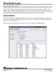
8. Appendix A - Mounting<br />
Figure 3 Mounting Detail