ProTalk Link Manual - Barnett Engineering Ltd
ProTalk Link Manual - Barnett Engineering Ltd
ProTalk Link Manual - Barnett Engineering Ltd

You also want an ePaper? Increase the reach of your titles
YUMPU automatically turns print PDFs into web optimized ePapers that Google loves.
Operating <strong>Manual</strong><br />
Hardware<br />
August 2012<br />
Rev. 2.0<br />
#215, 7710 – 5 th Street SE<br />
Calgary, Alberta, Canada<br />
T2H 2L9<br />
Phone: (403) 255-9544<br />
Fax: (403) 259-2343<br />
www.barnett-engg.com<br />
E-mail: sales@barnett-engg.com
TABLE OF CONTENTS<br />
1. INTRODUCTION.................................................................................. 1<br />
2. INSTALLATION OVERVIEW............................................................. 2<br />
3. M1 INSTALLATION ............................................................................ 6<br />
4. A1 INSTALLATION........................................................................... 10<br />
5. D1 INSTALLATION........................................................................... 13<br />
6. P1 INSTALLATION ........................................................................... 16<br />
7. T1 INSTALLATION ........................................................................... 21<br />
8. W1 INSTALLATION.......................................................................... 24<br />
9. W2 INSTALLATION.......................................................................... 28<br />
10. W3 INSTALLATION........................................................................ 32<br />
11. SPECIFICATIONS ............................................................................ 36<br />
12. HANDSET PROGRAMMING.......................................................... 53<br />
13. WARRANTY STATEMENT ............................................................ 76<br />
14. NOTICES........................................................................................... 77
INTRODUCTION PAGE 1<br />
1. INTRODUCTION<br />
The <strong>ProTalk</strong> <strong>Link</strong> modular alarm reporting system provides a flexible,<br />
effective solution to a wide variety of alarm monitoring situations at an<br />
unattended site. When an alarm condition occurs, such as building<br />
intrusion, power failure or equipment upset, the <strong>Link</strong> automatically places<br />
calls to inform people of the situation. These calls can be voice, e-mail,<br />
SMS text or paging depending on the selected communication module. In<br />
the case of unanswered voice calls, the <strong>Link</strong> will continue to dial through<br />
the list of programmed numbers until it successfully reaches someone and<br />
is able to report the alarm.<br />
An effective match between the alarm sources and the communication<br />
channels is easily done with plug together modules. Each system consists<br />
of one Main module and at least one communication module. The choice<br />
of communication module is determined by the type of channel (or<br />
channels) you want to call out on and more than one communication<br />
module can be used in cases where redundancy is required. For low<br />
density alarm counts, the input/output capabilities of a communication<br />
module will be adequate. When the alarm count exceeds this capacity,<br />
one or more of the discrete I/O modules can be used. The PLC module<br />
can be used to communicate directly with a controller without using<br />
individually wired connections.<br />
The <strong>ProTalk</strong> <strong>Link</strong> modules plug together to build up the system you want.<br />
Every system has one Main module and one or more expander modules.<br />
Throughout the manual, the modules are referred to in short form in this<br />
way: the B1285-M1 is an M1 module, the B1285-W1 is a W1 and so on.<br />
This manual contains information to help you install and configure a<br />
<strong>ProTalk</strong> <strong>Link</strong> alarm reporting system. For basic applications, a <strong>Link</strong><br />
system can be programmed with a safety approved Touch-Tone telephone<br />
by following the steps in this manual. For more advanced configurations,<br />
it will be necessary to use the PC programming application supplied with<br />
the unit. For details on programming with a PC, refer to the help files<br />
contained in the LINK.EXE PC application.<br />
The first sections in this manual show you how to install the <strong>Link</strong> system<br />
hardware followed by a description of the telset programming method.
PAGE 2<br />
INSTALLATION OVERVIEW<br />
2. INSTALLATION OVERVIEW<br />
The <strong>Link</strong> should be installed in a clean, dry indoor location suitable for<br />
electronic equipment.<br />
Caution: Power, telephone lines and antenna cables should be<br />
connected only after the installation is complete.<br />
Each system starts with a Main B1285-M1 module. The appropriate<br />
expander modules are then added to provide the required communications<br />
and I/O functionality. The first expander module is plugged into the Main<br />
module, then the next expander into the first expander and so on. The<br />
<strong>ProTalk</strong> <strong>Link</strong> System accepts a maximum of 16 modules (B1285-M1<br />
module + a maximum of 15 expander modules).<br />
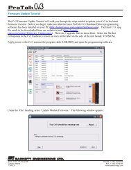
Connection of the plug-together modules is shown in Figure 1. Mounting<br />
ears are provided for back panel installation. A desktop arrangement can<br />
be also used where the modules are stacked on top of each other. Each<br />
added module is secured to the previous module with joiner plates<br />
attached to the sides.
INSTALLATION OVERVIEW PAGE 3<br />
EXPANDER MODULE<br />
MAIN MODULE<br />
Step 1: Position the expander module over<br />
the main module so the connectors<br />
line up then slide the parts together.<br />
EXPANDER MODULE<br />
MAIN MODULE<br />
Step 2: Fasten the two modules together with<br />
bolts through the joiner plates on each<br />
side.<br />
Figure 1 Module Connection<br />
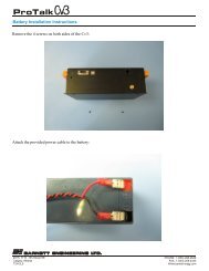
Every expander requires a unique address set<br />
by the rotary switch located on the top cover<br />
shown in Figure 2. Although the address<br />
setting and the physical location of the<br />
expander in the assembly are not related, the<br />
recommended method is to number the<br />
expanders from 1 upwards as they are<br />
connected together. If there is a PLC Figure 2 Address Switch<br />
module, it is recommended that any I/O or<br />
communications modules be addressed, starting from 1, then the PLC<br />
module given the next available address.
PAGE 4<br />
INSTALLATION OVERVIEW<br />
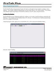
TOP VIEW<br />
FRONT VIEW<br />
Figure 3 Module Dimensions<br />
Figure 3 shows the dimensions for both Main and expander modules. The<br />
Main module does not have the connector on the bottom nor an address<br />
switch; it is always address 0.
INSTALLATION OVERVIEW PAGE 5<br />
EXPANDER MODULE<br />
(OPTIONAL)<br />
<strong>ProTalk</strong><br />
EXPANDER MODULE<br />
(OPTIONAL)<br />
<strong>ProTalk</strong><br />
<strong>ProTalk</strong><br />
PROGRAM<br />
PHONE<br />
CALL−OUT MODULE<br />
<strong>ProTalk</strong><br />
MAIN MODULE<br />
Figure 4 <strong>ProTalk</strong> LINK in a NEMA enclosure<br />
Figure 4 shows the <strong>ProTalk</strong> LINK, with three expanders, when it is<br />
mounted in a NEMA enclosure.
PAGE 6<br />
M1 INSTALLATION<br />
3. M1 INSTALLATION<br />
STATUS ALARM OUTPUT GROUP<br />
RUN<br />
RX/TX<br />
TONE<br />
VOICE<br />
SUPPLY<br />
PFAIL<br />
SYSTEM<br />
MAJOR<br />
MINOR<br />
1 2 1 2 3 4 5 6 7 8<br />
+PWR<br />
GND<br />
GND<br />
ACK<br />
PFAIL<br />
GND<br />
OUTPUT 1 OUTPUT 2<br />
PROGRAM<br />
USB DB9 TEL<br />
B1285-M1<br />
Figure 5 M1 Module Front Panel<br />
The M1 module controls all of the alarm reporting operations. An<br />
exception exists following a system failure when the communication<br />
modules change to autonomous mode and perform a basic callout (to<br />
announce the system failure). Communications and power to the<br />
expanders is taken through the mating connectors on the top and bottom of<br />
the modules.<br />
Connectors - Power and Signal<br />
Refer to Figure 7 for details of the connector pinouts and Figure 8 for<br />
details of the serial cable required for programming.<br />
Power<br />
Input voltage is connected to the M1 module only. Attach the ground<br />
lead of the external supply to the GND terminal and the positive lead<br />
to the +PWR terminal. Note that the chassis of the <strong>Link</strong> system is<br />
connected to ground. The <strong>Link</strong> System requires a power supply<br />
voltage of 10-30 VDC, 2.8A Max. The power supply used should be a<br />
safety approved Class 2 power supply source, current limited using a<br />
3A in-line slow-blow fuse.<br />
Total system power will depend on the number and type of modules<br />
that are in operation. Each module draws a maximum of 150 mA with<br />
all indicators on. The W1 and W2 modules are exceptions drawing 300<br />
mA and 650 mA respectively when transmitting at maximum power<br />
and all indicators on.<br />
Input power is monitored as an analog value by the M1 module and<br />
can be programmed as an alarm.<br />
Local Acknowledge Input<br />
If an external acknowledge pushbutton is to be used with the system it<br />
should be connected between the ACK terminal and ground; do not<br />
apply voltage to the ACK input. The pushbutton must be a normally<br />
open type. The circuit for ACK and PFAIL is shown in Figure 6.
M1 INSTALLATION PAGE 7<br />
Power Fail Input<br />
Figure 6 ACK and PFAIL Input Circuit<br />
If a power failure status is available from the external power supply, it<br />
can be connected between the PFAIL input and ground and then used<br />
to generate an alarm. The power fail signal must be a relay contact or<br />
open collector; do not apply voltage to the PFAIL input. In the<br />
programming for this alarm, the normal state can be set for either open<br />
or ground.<br />
Output Relays<br />
If external equipment is to be notified of system status conditions, the<br />
output relays can be used. Each of the two relays can be programmed<br />
to indicate one of these status conditions:<br />
New alarm exists<br />
Any alarm exists<br />
Acknowledge received<br />
Error condition<br />
Any of the 8 groups can be included in the status for each type.<br />
Connectors - Programming<br />
DB9<br />
This DTE RS232 programming port is used to:<br />
Transfer configuration data containing the programmed<br />
operating parameters<br />
Transfer voice data with the user programmed messages<br />
Transfer vocabulary data containing the 'canned' voices used<br />
by the system<br />
Upgrade files for flashing new code into the modules<br />
Monitor current system conditions
PAGE 8<br />
USB<br />
TEL<br />
M1 INSTALLATION<br />
The USB port performs the same function as the DB9 port. When a<br />
cable is plugged into this port, the DB9 port is not operational.<br />
The TEL port accepts a safety approved Touch-Tone telephone and is<br />
used to record the voice messages, interrogate points, acknowledge<br />
alarms and enter control codes. Limited programming functionality is<br />
available through the telset.<br />
Do not plug a telephone line into this port.<br />
Figure 7 M1 Module Connections<br />
Indicators<br />
Figure 8 M1 DB9 to PC Programming Cable<br />
The indicators are grouped into 4 sections:<br />
1) Status<br />
Run<br />
Flashing Red during startup while the flash memory is being<br />
checked and the system initialized.<br />
Red when in program mode, either by the local telset or a<br />
connected PC<br />
Green during normal operations<br />
Flashing green when in low power mode
M1 INSTALLATION PAGE 9<br />
RX/TX<br />
Green when a message is sent to an expander on the internal<br />
communications bus.<br />
Red if the message has to be resent due to a communications<br />
error<br />
Green/Red flash during PC communications<br />
Tone<br />
Flashes Green when a DTMF tone has been received.<br />
Off otherwise<br />
Voice<br />
Green when speaking<br />
Red when recording<br />
Off when idle<br />
2) Alarm<br />
Supply, Power Fail, System, Major, Minor<br />
Flashing Red with an unacknowledged alarm<br />
Solid Red with an acknowledged alarm<br />
Off when idle<br />
3) Output<br />
Two, one for each output<br />
Red when active<br />
Off otherwise<br />
4) Group<br />
Eight, one for each group<br />
Off if the group is disabled<br />
Green if the group is enabled and there are no alarms in the<br />
group<br />
Flashing Red if the group is enabled and there is an alarm in<br />
the group<br />
Flashing Yellow if the alarms in the group are in the process<br />
of being reported<br />
Solid Red when the alarms have been acknowledged
PAGE 10<br />
A1 INSTALLATION<br />
4. A1 INSTALLATION<br />
STATUS<br />
ALARM<br />
1 2 3<br />
4<br />
5 6 7 8 9 10 11 12<br />
13<br />
14 15 16<br />
RUN<br />
RX/TX<br />
OVER<br />
LOOP<br />
CURRENT INPUT<br />
VOLTAGE INPUT<br />
+<br />
1<br />
2 3<br />
+ + + 4<br />
+<br />
5<br />
+<br />
6<br />
7<br />
+ +<br />
8<br />
9<br />
10 11 12 13<br />
14<br />
15 16<br />
GND<br />
GND<br />
GND<br />
GND<br />
B1285-A1<br />
Figure 9 A1 Module Front Panel<br />
This module provides a total of 16 analog inputs; 8 using 4-20 mA current<br />
loop signals and 8 using single ended voltage inputs. The voltage inputs<br />
can be configured for +5, +10 or +30 VDC full scale. Each input can be<br />
independently configured for alarm reporting. The front panel shown in<br />
Figure 9 has all of the external connections as well as status indicators<br />
displaying the module state.<br />
Connections<br />
Front panel terminal block connections are shown in Figure 10.<br />
Current Loop Inputs<br />
Figure 10 Front Panel - Connections<br />
The first 8 inputs on the module are the current inputs. Each input has<br />
two terminals for placing it into the current loop. Current flow must be<br />
such that the current source enters the + terminal and exits from the -<br />
terminal. The input can be either at the top of the loop with the +<br />
terminal connected to the loop excitation voltage, or it can be at the<br />
bottom of the loop with the - terminal connected to the return of the<br />
loop excitation supply. Internal impedance is 100 ohms so the drop<br />
across the input is 2 VDC at full scale when 20 mA is flowing. The<br />
maximum common mode voltage that can be placed on the inputs is<br />
+35 VDC. If the loop is not connected or the current flow drops below<br />
4 mA, an open loop alarm can be generated. This alarm can be<br />
selected as either major or minor and is reported for the module and<br />
not for a specific input. A current input circuit is shown in Figure 11.
A1 INSTALLATION PAGE 11<br />
Voltage Inputs<br />
Figure 11 A1 Current Input Circuit<br />
Voltage inputs are configured by the programming application to<br />
match the full scale range of the analog input voltage; +5, +10 or +30<br />
VDC. If a voltage greater than the programmed maximum is applied,<br />
the result will be a full scale reading and an over voltage error can be<br />
generated. This alarm can be selected as either major or minor and is<br />
reported for the module and not for a specific input. A voltage input<br />
can withstand a constant voltage of up to +35 VDC regardless of the<br />
programmed range setting. The circuit for a voltage input is shown in<br />
Figure 12.<br />
Indicators<br />
Figure 12 A1 Voltage Input Circuit<br />
The indicators are grouped into 2 sections:<br />
1) Status<br />
Run<br />
Flashing Red during startup before a database is received<br />
from the main module<br />
Green during normal operations
PAGE 12<br />
A1 INSTALLATION<br />
RX/TX<br />
Normal operations<br />
Green on receipt of valid message from the main module<br />
Yellow if the message from the main module has a checksum<br />
error. This indicator times out after 400 msec<br />
Over<br />
Flashing Red when a voltage input is over range<br />
Off otherwise<br />
Loop<br />
Flashing Red when a current loop input is open<br />
Off otherwise<br />
2) Alarm<br />
Sixteen, one for each input<br />
Flashing Red when the associated input is in the alarm state<br />
Red when the associated input is in the alarm state and has<br />
been acknowledged<br />
Off when idle
D1 INSTALLATION PAGE 13<br />
5. D1 INSTALLATION<br />
STATUS<br />
ALARM<br />
RUN<br />
RX/TX<br />
CLEAR<br />
3 1 2 4 5 7 6 8 10 9 11<br />
12 13 14 15 16<br />
INPUT<br />
CLEAR<br />
1<br />
2 3 4 5 6 7 8 9 10 11 12 13 14 15 16 1 2 3 4<br />
B1285-D1<br />
GND<br />
GND<br />
GND<br />
GND<br />
Figure 13 D1 Module Front Panel<br />
The D1 module provides a total of 16 digital inputs that can be<br />
independently programmed to operate as one of five different types:<br />
Standard digital<br />
Watchdog timer<br />
Interval timer<br />
Totalizer<br />
Accumulator<br />
Each input can be programmed to accept three different signal level<br />
formats:<br />
Open / Ground<br />
Open / +Voltage between +5 and +30 VDC<br />
Ground /+Voltage between +5 and +30 VDC<br />
Clear inputs are used to reset the value of a totalizer or accumulator and<br />
are always associated with a specific digital input. Clear inputs 1 through<br />
4 work with digital inputs 1 through 4 respectively; totalizers or<br />
accumulators derived from other inputs can be reset using DTMF only.<br />
The signal format for each clear input is the same as its associated digital<br />
input. If the format is configured for Ground/+Voltage, the module can be<br />
programmed to generate an alarm when the input is open instead of in<br />
either of the expected states. This alarm can be selected as either major or<br />
minor and is reported for the module and not for a specific input.
PAGE 14<br />
Connections<br />
Connection points for the inputs are shown in Figure 14.<br />
D1 INSTALLATION<br />
Figure 14 D1 Front Panel - Connections<br />
The circuit for the inputs is shown in Figure 15.<br />
Indicators<br />
Figure 15 D1 Input Circuit<br />
The indicators are grouped into 2 sections:<br />
1) Status<br />
Run<br />
Flashing Red during startup before a database is received<br />
from the main module<br />
Green during normal operations<br />
RX/TX<br />
Normal operations<br />
Green on receipt of valid message from the main module<br />
Yellow if the message from the main module has a checksum<br />
error. This indicator times out after 400 msec<br />
Clear<br />
Green when any clear input is active<br />
Off when all clear inputs are idle
D1 INSTALLATION PAGE 15<br />
2) Alarm<br />
Sixteen, one for each input<br />
Flashing Red when the associated input is in the alarm state<br />
Yellow when there is an error with an input connection<br />
Red when the associated input is in the alarm state and has<br />
been acknowledged<br />
Green when active as an Interval or Accumulator<br />
Off when idle
PAGE 16<br />
P1 INSTALLATION<br />
6. P1 INSTALLATION<br />
STATUS<br />
COMM<br />
ALARM BLOCK<br />
0 1 3 2 4 7 5 6 8 9<br />
10<br />
11 12 13 14<br />
15<br />
RUN<br />
RX/TX<br />
PORT<br />
RX/TX<br />
ETHERNET<br />
RS232<br />
RS485<br />
LINK<br />
ACT<br />
(A)-<br />
(B)+<br />
GND<br />
B1285-P1<br />
Figure 16 P1 Module - Front Panel<br />
The P1 module provides connectivity between the <strong>Link</strong> system and a PLC.<br />
Communications between the P1 module and the PLC can be done using<br />
one of the available ports: the RS232 serial port, the RS485 serial port or,<br />
for Modbus systems, the Ethernet port. Only one of the three ports can be<br />
assigned for PLC communications at a time. The Ethernet port is<br />
available for monitoring the status of the <strong>Link</strong> system regardless of which<br />
port is selected for PLC communications.<br />
Protocols used by the module are:<br />
<br />
<br />
<br />
<br />
<br />
<br />
Modbus slave<br />
Modbus master<br />
Modbus TCP/IP slave<br />
Modbus TCP/IP master<br />
Allen-Bradley DF1 Point-to-Point PLC5 master<br />
Allen-Bradley DF1 Point-to-Point SLC-500 master.<br />
Connectors<br />
RS232<br />
Figure 17 P1 Module - Connectors<br />
This DTE RS232 serial port connected to the communications port of<br />
the PLC. Either this port or the RS485 port is selected in the<br />
configuration; both do not operate at the same time.
P1 INSTALLATION PAGE 17<br />
RS485<br />
The RS485 port performs the same function as the RS232 port. Either<br />
this port or the RS232 port is selected in the configuration; both do not<br />
operate at the same time.<br />
ETHERNET<br />
Ethernet connectivity with the <strong>Link</strong> system is available through this<br />
port. TCP/IP communications with the PLC and system monitoring<br />
are done here.<br />
Indicators<br />
The indicators are grouped into 4 sections:<br />
1) Status<br />
Run<br />
Flashing Red during startup before a database is received<br />
from the main module<br />
Green during normal operations<br />
RX/TX<br />
Normal operations<br />
Green on receipt of valid message from the main module<br />
Yellow if the message from the main module has a checksum<br />
error. This indicator times out after 400 msec<br />
2) Comm<br />
Port<br />
Green if the Ethernet port has been selected<br />
Yellow if the RS232 port has been selected<br />
Red if the RS485 port has been selected<br />
RX/TX (RS232 and RS485 only)<br />
Solid Green during initial message poll<br />
Solid Red during a message retry<br />
3) Alarm Block<br />
Sixteen, one for each of the first 16 blocks of the system<br />
Flashing Red when any point in a block is in the alarm state<br />
Solid Red when all alarms in a block are acknowledged<br />
Off when all points are idle<br />
4) Ethernet Connector<br />
<strong>Link</strong><br />
Illuminated when the cable is connected<br />
Active<br />
Illuminated when packets are being transferred
PAGE 18<br />
Communications Error Codes<br />
P1 INSTALLATION<br />
Modbus Error Codes<br />
00 success<br />
01 illegal function<br />
02 illegal data address<br />
03 illegal data value<br />
04 failure in associated device<br />
05 acknowledge long command<br />
06 "busy, rejected message"<br />
07 NAK - negative acknowledge<br />
08 memory parity error<br />
FD<br />
FE<br />
FF<br />
not enough characters<br />
CRC error<br />
no response<br />
00 success<br />
Data Highway and DH-485 Error Codes<br />
x2<br />
x3<br />
x4<br />
x5<br />
x6<br />
x7<br />
x8<br />
cannot guarantee delivery, link layer<br />
duplicate token holder detected<br />
local port is disconnected<br />
application layer timed out waiting for a response<br />
duplicate node detected<br />
station is off-line<br />
hardware fault<br />
1x<br />
2x<br />
3x<br />
4x<br />
5x<br />
6x<br />
7x<br />
illegal command or format<br />
host has a problem and will not communicate<br />
remote node host is missing, disconnected, or shut down<br />
host could not complete function due to hardware fault<br />
addressing problem or memory protected rungs<br />
function disallowed due to command protection selection<br />
processor is in program mode
P1 INSTALLATION PAGE 19<br />
8x<br />
9x<br />
Bx<br />
Cx<br />
compatibility mode file missing or communication zone problem<br />
remote node cannot buffer command<br />
remote node problem due to download<br />
cannot execute command due to active IPBs<br />
D1<br />
D2<br />
D3<br />
D4<br />
D5<br />
D6<br />
D7<br />
D8<br />
D9<br />
DA<br />
DB<br />
DC<br />
DD<br />
DE<br />
DF<br />
E0<br />
E1<br />
E2<br />
E3<br />
E4<br />
E5<br />
E6<br />
E7<br />
E8<br />
E9<br />
EA<br />
EB<br />
a field has an illegal value<br />
less levels specified in address than minimum for any address<br />
more levels specified in address than system supports<br />
symbol not found<br />
symbol is of improper format<br />
address doesn't point to something<br />
file wrong size<br />
cannot complete request, situation has changed since the start of the<br />
command<br />
data or file is too large<br />
transaction size plus word address is too large<br />
access denied, improper privilege<br />
condition cannot be generated - resource is not available<br />
condition already exists - resource is already available<br />
command cannot be executed<br />
histogram overflow<br />
no access<br />
illegal data type<br />
invalid parameter or invalid data<br />
address reference exists to deleted area<br />
command execution failure for unknown reason<br />
data conversion error<br />
scanner not able to communicate with 1771 rack adapter<br />
adapter cannot communicate with module<br />
1771 module response was not valid<br />
duplicated label<br />
file is open; another node owns it<br />
another node is the program owner
PAGE 20<br />
P1 INSTALLATION<br />
FD<br />
FE<br />
FF<br />
not enough characters<br />
CRC error<br />
no response
T1 INSTALLATION PAGE 21<br />
7. T1 INSTALLATION<br />
STATUS<br />
ALARM<br />
OUTPUT<br />
RUN<br />
RX/TX<br />
TONE<br />
HOOK<br />
MODEM<br />
RADIO<br />
1<br />
2<br />
3 4 5 6<br />
7 8 1<br />
2 3 4<br />
INPUT<br />
OUTPUT 1<br />
OUTPUT 2 OUTPUT 3<br />
OUTPUT 4<br />
RADIO<br />
1<br />
3 2 4 6 5 7<br />
8<br />
GND<br />
GND<br />
TELCO<br />
TX<br />
RX<br />
PTT<br />
COS<br />
GND<br />
GND<br />
B1285-T1<br />
Figure 18 T1 Module Front Panel<br />
The T1 module provides callout capability on a telephone line and/or a<br />
mobile radio port. The radio port can also be used to operate a public<br />
address system. In addition to communications functions, this module<br />
also has 8 digital inputs that can be independently programmed to operate<br />
as one of five different types:<br />
Standard digital<br />
Watchdog timer<br />
Interval timer<br />
Totalizer<br />
Accumulator<br />
There are also 4 relay outputs that can be used for remote control; these<br />
relays are controlled by incoming DTMF codes.<br />
Connectors<br />
Refer to Figure 19 for details of the connector pinouts.<br />
Inputs<br />
Figure 19 T1 Module Connections<br />
The eight digital inputs operate with a dry relay contact or open<br />
collector to ground as shown in Figure 20. In the open state the input<br />
is pulled high internally and in the ground state it is pulled to ground.
PAGE 22<br />
Relay Outputs<br />
T1 INSTALLATION<br />
Each of the 4 relays can be configured during programming to provide<br />
remote control outputs that are operated by DTMF codes.<br />
Telco RJ11<br />
Figure 20 T1 Input Circuit<br />
This is the port that connects to a conventional telephone line and is<br />
used by the T1 module to place calls and announce alarm messages.<br />
There is an on-board modem that provides the ability to answer<br />
incoming data calls if a DTMF modem code has first been entered.<br />
The T1 module can be called through this port by the <strong>Link</strong><br />
configuration application, allowing configuration settings to be<br />
remotely changed using the PC. A limited amount of programming<br />
can also be done using a Touch-Tone set to call into the module.<br />
Radio Port<br />
Connection to a land mobile base station is through this port. The<br />
signals available are:<br />
TX<br />
RX<br />
PTT<br />
COS<br />
Audio from the T1 module to the radio<br />
Audio from the radio to the T1 module<br />
Ground closure from the T1 module to activate the radio<br />
transmitter<br />
Ground closure from the radio to indicate the radio<br />
channel is busy<br />
A public address system can be connected to the module using just the<br />
TX and PTT lines.
T1 INSTALLATION PAGE 23<br />
Indicators<br />
The indicators are grouped into 3 sections:<br />
1) Status<br />
Run<br />
Flashing Red during startup before a database is received<br />
from the main module<br />
Green during normal operations<br />
RX/TX<br />
Green on receipt of valid message from the main module<br />
Yellow if the message from the main module has a checksum<br />
error. This indicator times out after 400 msec<br />
Tone<br />
Green when a tone is being received<br />
Red when a tone is being transmitted<br />
Off when idle<br />
Hook<br />
Red when ringing on an incoming call<br />
Green when off hook<br />
Off when idle<br />
Modem<br />
Green when modem is waiting for a connection<br />
Yellow when connected<br />
Red when disconnected<br />
Off when idle<br />
Radio<br />
Green when PTT is active<br />
Red when the channel is busy<br />
Off when idle<br />
2) Alarm<br />
Eight, one for each input<br />
Flashing Red when the associated input is in the alarm state<br />
Red when the associated input is in the alarm state and has<br />
been acknowledged<br />
Green when active as an Interval or Accumulator<br />
Off when idle<br />
3) Output<br />
Four, one for each output<br />
Red when the relay is in the on state<br />
Yellow if the relay has failed<br />
Off otherwise
PAGE 24<br />
W1 INSTALLATION<br />
8. W1 INSTALLATION<br />
STATUS<br />
ALARM<br />
OUTPUT<br />
RUN<br />
RX/TX<br />
TONE<br />
MODE<br />
MODEM<br />
RSSI<br />
1 2 3 4 5 6 7 8<br />
1 2<br />
3<br />
4<br />
INPUT<br />
OUTPUT 1<br />
OUTPUT 2<br />
OUTPUT 3<br />
OUTPUT 4<br />
1<br />
2 3 4 5 6 7 8<br />
GND<br />
GND<br />
B1285-W1<br />
Figure 21 W1 Module Front Panel<br />
The W1 module provides wireless callout capability through an embedded<br />
GSM cell phone. In addition to communications functions, this module<br />
also has 8 digital inputs that can be independently programmed to operate<br />
as one of five different types:<br />
Standard digital<br />
Watchdog timer<br />
Interval timer<br />
Totalizer<br />
Accumulator<br />
There are also 4 relay outputs that can be used for remote control; these<br />
relays are controlled by incoming DTMF codes.<br />
For more advanced callout requirements, the module can be configured to<br />
send e-mail messages containing the alarm information. A limited amount<br />
of programming can also be done using a Touch-Tone set locally or by<br />
calling into the module.<br />
This module can also be used to transfer a database to the <strong>ProTalk</strong> <strong>Link</strong> if<br />
the internal cell phone is registered with a data plan through the wireless<br />
carrier. See the LINK.EXE pc application’s Help section for details on<br />
using this feature.<br />
Connectors<br />
Refer to Figure 22 below for details of the connector pinouts.<br />
Figure 22 W1 Module Connections
W1 INSTALLATION PAGE 25<br />
Inputs<br />
The eight digital inputs operate with a dry relay contact or open<br />
collector to ground as shown in Figure 23. In the open state the input<br />
is pulled high internally and in the ground state it is pulled to ground.<br />
Relay Outputs<br />
Figure 23 W1 Input Circuit<br />
Each of the 4 relays can be configured during programming to provide<br />
remote control outputs that are operated by DTMF codes.<br />
Indoor Antenna<br />
Indoor Antenna Installation<br />
Figure 24 Indoor Antenna<br />
Indicators<br />
The indicators are grouped into 3 sections:<br />
1) Status<br />
For the W1 <strong>Link</strong> module to<br />
successfully make cellular calls,<br />
there must be adequate signal<br />
strength at its antenna port. The<br />
flex antenna supplied with the<br />
module is suitable for installations<br />
where there is sufficient signal<br />
strength. This configuration is<br />
shown in Figure 24.<br />
Run<br />
Flashing Red during startup before a database is received<br />
from the main module<br />
Green during normal operations<br />
RX/TX<br />
Green on receipt of valid message from the main module<br />
Yellow if the message from the main module has a checksum<br />
error. This indicator times out after 400 msec
PAGE 26<br />
Tone<br />
Green when a tone is being received<br />
Red when a tone is being transmitted<br />
Off when idle<br />
W1 INSTALLATION<br />
Mode<br />
Green when connected to the home cellular network<br />
Yellow when connected to cellular network and roaming<br />
Red/Green flashing when ringing or call in progress<br />
Red when status is disconnected<br />
Off otherwise<br />
Modem<br />
Green when modem is enabled<br />
Yellow when the modem has a data connection<br />
Red when disconnecting<br />
Off when disconnected<br />
RSSI<br />
Flashing Red when RSSI is 0 (very poor)<br />
Red when RSSI is between 1 and 3 (poor)<br />
Yellow when RSSI is 4 or 5 (marginal)<br />
Green when RSSI is 6 or greater (good)<br />
Off for undetectable or unknown RSSI<br />
2) Alarm<br />
Eight, one for each input<br />
Flashing Red when the associated input is in the alarm state<br />
Red when the associated input is in the alarm state and has<br />
been acknowledged<br />
Green when active as an Interval or Accumulator<br />
Off when idle<br />
3) Output<br />
Four, one for each output<br />
Red when the relay is in the on state<br />
Yellow if the relay has failed<br />
Off otherwise
W1 INSTALLATION PAGE 27<br />
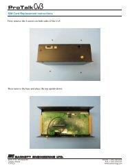
SIM Card Installation<br />
The B1285-W1 utilizes an embedded GSM cell phone module to make<br />
calls. To operate on a wireless network, a valid SIM card (Subscriber<br />
Identity Module) must be obtained from your carrier and installed in this<br />
module. The SIM cardholder is located inside the cell phone module; it is<br />
necessary to remove the top from the B1285-W1 case in order to gain<br />
access to the cell phone module. It is important to observe proper<br />
electrostatic grounding precautions and to disconnect power prior to<br />
performing this procedure.<br />
What you’ll need:<br />
Phillips screwdriver<br />
Active SIM card<br />
Installation Steps:<br />
Separate the W1 module from the connecting unit(s) by removing<br />
the screws from the connector plates on either side of the unit.<br />
Remove the four black screws holding the lid on.<br />
Remove the two silver screws on the top of the unit and separate<br />
the lid from the base. Note: there is an aluminum shim around<br />
the DB15 connector that is necessary for assembly. Don’t lose it.<br />
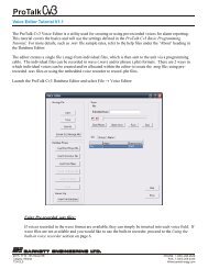
Position the unit so the front is facing away from you.<br />
You will see a silver Modem Module on the circuit board. On<br />
the edge closest to you is where you will find the SIM card holder<br />
(Figure 25 below).<br />
To access the holder, use a fine point object to depress the yellow<br />
eject button.<br />
Remove the small black holder and place the SIM card in the<br />
holder taking note of the keyed pad.<br />
Return the holder with the SIM card to the space in the Modem<br />
Module.<br />
Ensure the aluminum shim is around the DB15 connector.<br />
Put the lid on and replace the silver screws on the top of the unit.<br />
Replace the four black screws that secure the lid.<br />
Reattach the W1 to the connecting units using the connector<br />
plates and remaining screws.<br />
Figure 25 Rear View of Modem Module
PAGE 28<br />
W2 INSTALLATION<br />
9. W2 INSTALLATION<br />
STATUS<br />
ALARM<br />
OUTPUT<br />
RUN<br />
RX/TX<br />
TONE<br />
MODE<br />
MODEM<br />
RSSI<br />
1 2 3 4 5 6 7 8<br />
1 2<br />
3<br />
4<br />
INPUT<br />
OUTPUT 1<br />
OUTPUT 2<br />
OUTPUT 3<br />
OUTPUT 4<br />
DATA<br />
1<br />
2 3 4 5 6 7 8<br />
GND<br />
GND<br />
B1285-W2<br />
Figure 26 W2 Module Front Panel<br />
The W2 module provides wireless callout capability through an embedded<br />
CDMA cell phone. In addition to communications functions, this module<br />
also has 8 digital inputs that can be independently programmed to operate<br />
as one of five different types:<br />
Standard digital<br />
Watchdog timer<br />
Interval timer<br />
Totalizer<br />
Accumulator<br />
There are also 4 relay outputs that can be used for remote control; these<br />
relays are controlled by incoming DTMF codes.<br />
A limited amount of programming can also be done using a safety<br />
approved Touch-Tone telephone locally or by calling into the module.<br />
This module can be used to transfer a database to the <strong>ProTalk</strong> <strong>Link</strong> if the<br />
internal cell phone is registered with a data plan through the wireless<br />
carrier. It can also transfer data between the external DB9 connector and<br />
the cell phone’s modem. See the LINK.EXE PC application’s Help<br />
section for details on using these features.<br />
Connectors<br />
Refer to Figure 27 below for details of the connector pin outs.<br />
Figure 27 W2 Module Connections
W2 INSTALLATION PAGE 29<br />
Inputs<br />
The eight digital inputs operate with a dry relay contact or open<br />
collector to ground as shown in Figure 28. In the open state the input<br />
is pulled high internally and in the ground state it is pulled to ground.<br />
Relay Outputs<br />
Figure 28 W2 Input Circuit<br />
Each of the 4 relays can be configured during programming to provide<br />
remote control outputs that are operated by DTMF codes.<br />
Antenna<br />
Connection of the external antenna is at the SMA female coax<br />
connector.<br />
Indoor Antenna Installation<br />
Figure 29 Indoor Antenna<br />
Indicators<br />
The indicators are grouped into 3 sections:<br />
1) Status<br />
For the W2 <strong>Link</strong> module to<br />
successfully make cellular calls,<br />
there must be adequate signal<br />
strength at its antenna port. The<br />
flex antenna supplied with the<br />
module is suitable for installations<br />
where there is sufficient signal<br />
strength. This configuration is<br />
shown in Figure 29.<br />
Run<br />
Flashing Red during startup before a database is received<br />
from the main module<br />
Green during normal operations
PAGE 30<br />
W2 INSTALLATION<br />
RX/TX<br />
Green on receipt of valid message from the main module<br />
Yellow if the message from the main module has a checksum<br />
error. This indicator times out after 400 msec<br />
Tone<br />
Green when a tone is being received<br />
Red when a tone is being transmitted<br />
Off when idle<br />
Mode<br />
Green when connected to the home cellular network<br />
Yellow when connected to cellular network and roaming<br />
Red/Green flashing when ringing or call in progress<br />
Red when disconnected<br />
Off otherwise<br />
Modem<br />
Green when the modem is enabled<br />
Yellow when the modem has a data connection<br />
Red when disconnecting<br />
Off when disconnected<br />
RSSI<br />
Flashing Red when RSSI is 0 (very poor)<br />
Red when RSSI is between 1 and 3 (poor)<br />
Yellow when RSSI is 4 or 5 (marginal)<br />
Green when RSSI is 6 or greater (good)<br />
Off for undetectable or unknown RSSI<br />
2) Alarm<br />
Eight, one for each input<br />
Flashing Red when the associated input is in the alarm state<br />
Red when the associated input is in the alarm state and has<br />
been acknowledged<br />
Green when active as an Interval or Accumulator<br />
Off when idle<br />
3) Output<br />
Four, one for each output<br />
Red when the relay is in the on state<br />
Yellow if the relay has failed<br />
Off otherwise<br />
CDMA Module Activation<br />
The B1285-W2 utilizes an embedded CDMA cell phone module to make<br />
calls. To operate on a wireless network, a valid MIN (Mobile<br />
Identification Number) and/or MDN (Mobile Directory Number) must be<br />
obtained from your carrier and programmed into the unit.
W2 INSTALLATION PAGE 31<br />
For programming instructions, refer to Wireless Module Programming in<br />
the Handset Programming section or to the <strong>ProTalk</strong> <strong>Link</strong> PC software and<br />
associated help files.
PAGE 32<br />
W3 INSTALLATION<br />
10. W3 INSTALLATION<br />
STATUS<br />
ALARM<br />
OUTPUT<br />
RUN<br />
RX/TX<br />
TONE<br />
MODE<br />
MODEM<br />
RSSI<br />
1 2 3 4 5 6 7 8 1 2 3 4<br />
INPUT<br />
OUTPUT 1<br />
OUTPUT 2<br />
OUTPUT 3<br />
OUTPUT 4<br />
SIM<br />
1<br />
2 3 4 5 6<br />
7 8<br />
GND<br />
GND<br />
B1285-W 3<br />
Figure 30 W3 Module Front Panel<br />
The W3 module provides wireless callout capability through an embedded<br />
HSPA cell phone. In addition to communications functions, this module<br />
also has 8 digital inputs that can be independently programmed to operate<br />
as one of five different types:<br />
Standard digital<br />
Watchdog timer<br />
Interval timer<br />
Totalizer<br />
Accumulator<br />
There are also 4 relay outputs that can be used for remote control; these<br />
relays are controlled by incoming DTMF codes.<br />
For more advanced callout requirements, the module can be configured to<br />
send e-mail and text messages containing the alarm information and can<br />
also receive text messages containing control codes. A limited amount of<br />
programming can also be done using a Touch-Tone set locally or by<br />
calling into the module.<br />
This module can also be used to transfer a database to the <strong>ProTalk</strong> <strong>Link</strong> if<br />
the internal cell phone is registered with a data plan through the wireless<br />
carrier. See the LINK.EXE pc application’s Help section for details on<br />
using this feature.<br />
Connectors<br />
Refer to Figure 31 below for details of the connector pinouts.<br />
Figure 31 W3 Module Connections
W3 INSTALLATION PAGE 33<br />
Inputs<br />
The eight digital inputs operate with a dry relay contact or open<br />
collector to ground as shown in Figure 32. In the open state the input<br />
is pulled high internally and in the ground state it is pulled to ground.<br />
Relay Outputs<br />
Figure 32 W3 Input Circuit<br />
Each of the 4 relays can be configured during programming to provide<br />
remote control outputs that are operated by DTMF codes.<br />
Indoor Antenna<br />
Indoor Antenna Installation<br />
Figure 33 Indoor Antenna<br />
Indicators<br />
The indicators are grouped into 3 sections:<br />
1) Status<br />
For the W3 <strong>Link</strong> module to<br />
successfully make cellular calls, there<br />
must be adequate signal strength at its<br />
antenna port. The flex antenna<br />
supplied with the module is suitable<br />
for installations where there is<br />
sufficient signal strength. This<br />
configuration is shown in Figure 33.<br />
Run<br />
Flashing Red during startup before a database is received<br />
from the main module<br />
Green during normal operations<br />
RX/TX<br />
Green on receipt of valid message from the main module<br />
Yellow if the message from the main module has a checksum<br />
error. This indicator times out after 400 msec
PAGE 34<br />
Tone<br />
Green when a tone is being received<br />
Red when a tone is being transmitted<br />
Off when idle<br />
W3 INSTALLATION<br />
Mode<br />
Green when connected to the home cellular network<br />
Yellow when connected to cellular network and roaming<br />
Red/Green flashing when ringing or call in progress<br />
Red when status is disconnected<br />
Off otherwise<br />
Modem<br />
Green when modem is enabled<br />
Yellow when the modem has a data connection<br />
Red when disconnecting<br />
Off when disconnected<br />
RSSI<br />
Flashing Red when RSSI is 0 (very poor)<br />
Red when RSSI is between 1 and 3 (poor)<br />
Yellow when RSSI is 4 or 5 (marginal)<br />
Green when RSSI is 6 or greater (good)<br />
Off for undetectable or unknown RSSI<br />
2) Alarm<br />
Eight, one for each input<br />
Flashing Red when the associated input is in the alarm state<br />
Red when the associated input is in the alarm state and has<br />
been acknowledged<br />
Green when active as an Interval or Accumulator<br />
Off when idle<br />
3) Output<br />
Four, one for each output<br />
Red when the relay is in the on state<br />
Yellow if the relay has failed<br />
Off otherwise
W3 INSTALLATION PAGE 35<br />
SIM Card Installation<br />
The B1285-W3 utilizes an embedded HSPA cell phone module to make<br />
calls. To operate on a wireless network, a valid SIM card (Subscriber<br />
Identity Module) must be obtained from your carrier and installed in this<br />
module. The SIM cardholder is located on the front of the case. It is<br />
important to observe proper electrostatic grounding precautions and to<br />
disconnect power prior to performing this procedure.<br />
What you’ll need:<br />
Fine point object (eg. paper clip)<br />
Active SIM card<br />
Installation Steps:<br />
Use a fine point object to depress the yellow eject button.<br />
Remove the small black holder and place the SIM card in the<br />
holder taking note of the keyed pad.<br />
Return the holder with the SIM card through the slot in the front<br />
of the case.
PAGE 36<br />
SPECIFICATIONS<br />
11. SPECIFICATIONS<br />
11.1 Common module specifications<br />
Physical:<br />
Environmental:<br />
Power:<br />
8.9″ wide x 2.42″ high x 4.32″ deep<br />
Steel, powder coated matte black<br />
Mounting ears for panel installation<br />
-40°C to + 60°C, 95% humidity, non-condensing<br />
+10 VDC to +30 VDC<br />
Expander output: DB15 female (top of case to additional expander<br />
modules)<br />
Expander input: DB15 male (bottom of case to previous expander<br />
modules) not present on the M1 module<br />
Address Selector: 16 position rotary switch, access from the enclosure top<br />
Not present on the M1 module
SPECIFICATIONS PAGE 37<br />
11.2 Detailed module specifications<br />
11.2.1 M1 Module<br />
This module is responsible for the operation of the <strong>Link</strong> system - consult<br />
the Programming section of this manual or the Help section of the<br />
LINK.EXE PC application for details on how the M1 module operates.<br />
Digital Inputs:<br />
Relay Outputs:<br />
Program Ports:<br />
2 total, dedicated as power fail and acknowledge inputs<br />
Input Levels: open / ground closure<br />
Impedance: 20k ohms<br />
Maximum +voltage: +30 VDC<br />
2 total, form C, 1A at 30 VDC<br />
DB9<br />
USB<br />
RS232, DTE 57,600 baud, 1 stop, no parity<br />
Connects to a PC for configuration programming,<br />
code updating and monitoring<br />
USB2<br />
Same function as the DB9 port 1, disables the DB9<br />
when connected to a PC<br />
Telset program port<br />
RJ11<br />
Connects to a DTMF telset for voice programming<br />
and limited configuration programming<br />
Programmable Features<br />
Site Name:<br />
This is a string of up to 16 characters usually<br />
representing the location of the <strong>Link</strong> system. The name<br />
is not used in voice announcements but is used for<br />
messages sent by e-mail and in the Monitor operation<br />
that can be accessed by connecting to the main module<br />
with this application or through the internet if a PLC<br />
module is in the system.<br />
Normally the Site Name will be the same or similar to<br />
the voice message for this point.<br />
Battery Voltage: Internally connected to the primary DC power supply<br />
and can be programmed as an analog alarm.<br />
Maximum signal full scale:<br />
Decimal maximum:<br />
Decimal minimum:<br />
Units:<br />
+30 VDC only<br />
+30.00 only<br />
0 only<br />
Volts
PAGE 38<br />
Power Failure:<br />
Relay Outputs:<br />
SPECIFICATIONS<br />
Connected to external power fail signal and can be<br />
programmed as a digital alarm with ground closure<br />
operation.<br />
Each of the two relays can be programmed to indicate<br />
one of these status conditions:<br />
New alarm exists<br />
Any alarm exists<br />
Acknowledge received<br />
Error condition<br />
Any of the 8 groups can be included in the status for<br />
these states.<br />
These relays are not programmable as remote control<br />
outputs.<br />
Major Alarm:<br />
Minor Alarm:<br />
This system alarm is the product of ORing all of the<br />
major alarms that can be set in each module. If enabled<br />
it produces the message 'Major alarm' when<br />
annunciated.<br />
This system alarm is the product of ORing all of the<br />
minor alarms that can be set in each module. If enabled<br />
it produces the message 'Minor alarm' when<br />
annunciated.<br />
System Alarms: Individual alarms can be set for:<br />
Vocabulary Error - checksum memory error detected<br />
Database Error - checksum memory error detected<br />
User Voice Error - checksum memory error detected<br />
Clock Error - invalid time value<br />
Expander Failure - any configured expander module<br />
is not responding<br />
11.2.2 A1 Module<br />
Analog Inputs:<br />
8 current loop inputs:<br />
Impedance: 100 ohms floating<br />
Maximum common mode voltage: +35 VDC<br />
Operating range: 4-20 mA DC<br />
8 voltage inputs:<br />
Single ended analog voltage referenced to ground<br />
Impedance: 110k ohms to ground<br />
Operating range: programmable for +5, +10<br />
or +30 VDC full scale<br />
Maximum input voltage: +35 VDC
SPECIFICATIONS PAGE 39<br />
Programmable features<br />
Input<br />
Calibration:<br />
Delay Time:<br />
Major/Minor<br />
Alarm:<br />
Full scale (current inputs): 20 mA only<br />
Full scale (voltage inputs): +5, +10 or +30 VDC<br />
Decimal maximum +9999<br />
Decimal minimum -9999<br />
Hysteresis 1% to 25%<br />
Millisecond scale 10 to 65530 msec. in 10 msec. steps.<br />
Second scale 1 to 65535 seconds.<br />
Independent on and off delay settings<br />
Current Loop is open<br />
Voltage Input is over range<br />
11.2.3 D1 Module<br />
Digital Inputs:<br />
Clear Inputs:<br />
16 total<br />
Impedance: 250k ohms<br />
Maximum +voltage: +30 VDC<br />
Minimum +voltage: +5 VDC<br />
4 total, function as clear controls for digital inputs that<br />
are programmed as a totalizer or accumulator on inputs<br />
1 to 4 respectively.<br />
Input format is the same as the setting for the associated<br />
digital input<br />
Impedance: 250k ohms<br />
Maximum +voltage: +30 VDC<br />
Minimum +voltage: +5 VDC<br />
Programmable Features<br />
Digital Inputs:<br />
Major/Minor<br />
Alarm:<br />
Can be standard digital, watchdog, pulse width, totalizer<br />
or accumulator types<br />
Input format:<br />
open / ground closure<br />
open / +voltage<br />
ground / +voltage<br />
Input open with format set for ground / +voltage
PAGE 40<br />
11.2.4 P1 Module<br />
Communications<br />
Ports:<br />
RS232 (DTE) DB9<br />
or RS485 (2 wire terminal block), selectable<br />
Ethernet<br />
SPECIFICATIONS<br />
Programmable Features<br />
Major/Minor<br />
Alarms:<br />
Communications<br />
Ports:<br />
Block<br />
Addressing:<br />
Each of these can be either a major or minor alarm:<br />
Ethernet link failure - when the link is lost due to a<br />
network disruption or disconnected cable.<br />
E-mail undeliverable - indicates that an e-mail<br />
transmission did not reach the STMP server.<br />
RS232 or RS485 (selectable)<br />
Stop bit: 1<br />
Parity: even, odd or none<br />
Checksum:<br />
Baud rate: 300<br />
1200<br />
2400<br />
4800<br />
9600<br />
19200<br />
38400<br />
57600<br />
115200<br />
Ethernet:<br />
IP address:<br />
Subnet mask:<br />
Default gateway:<br />
E-mail server:<br />
Data Type<br />
CRC or BCC (A-B modes)<br />
CRC (Modbus modes)<br />
set by system administrator<br />
set by system administrator<br />
set by system administrator<br />
set by system administrator<br />
Type defines the data type for the 16 registers in a<br />
block. For a PLC location Type can be bit, analog or<br />
bit array. For blocks that are occupied with other<br />
<strong>Link</strong> modules, Type will be defined by the hardware<br />
in that module.
SPECIFICATIONS PAGE 41<br />
Unit ID<br />
Each block, consisting of 16 points, is assigned a<br />
Unit ID which is the address of the PLC. In slave<br />
mode all of the Unit ID values will be the same,<br />
changing this value in any block 0 will change all<br />
blocks. In master mode, each block can be assigned<br />
its own Unit ID to allow communications with<br />
multiple PLCs.<br />
Start Address<br />
Each block requires a value that represents the<br />
starting address of 16 sequential PLC registers. In<br />
master mode this address will be the register location<br />
in the PLC. In slave mode, Start is arbitrarily<br />
assigned starting with 1 in the first location in block<br />
0 then in ascending order through the 32 blocks.<br />
11.2.5 T1 module<br />
Digital Inputs:<br />
Relay Outputs:<br />
Telco port:<br />
Radio port:<br />
8 total, ground closure operation<br />
Internally pulled up to +5 VDC<br />
1 M ohm input impedance<br />
Programmable as standard digital, watchdog, pulse<br />
width, totalizer or accumulator types<br />
4 total, form C, 3A at 30 VDC<br />
Programmable as on/off or timed<br />
Latching coils, can be programmed to maintain previous<br />
state on power-up<br />
RJ11<br />
Connects to telephone line<br />
TX audio: 600 ohms, single ended, capacitively coupled<br />
adjustable -20 dBm to 0 dBm<br />
RX audio: 10K ohms, single ended, capacitively coupled<br />
adjustable -20 dBm to 0 dBm<br />
PTT: open collector, 25 VDC max, 100 mA max<br />
COS: 10K ohms, ground closure<br />
Programmable Features<br />
Major/Minor<br />
Alarms:<br />
Each of these can be either a major or minor alarm:
PAGE 42<br />
PTT Warmup:<br />
COS Detect:<br />
Audio Levels:<br />
Rings Before<br />
Answer:<br />
SPECIFICATIONS<br />
Relay Failure - when the contact position does not<br />
match the coil setting<br />
No dial tone - when there is no dial tone because the<br />
telco line is not connected or the port has been<br />
damaged<br />
The interval between when the PTT signal is asserted to<br />
activate the radio transmitter and the beginning of the<br />
message.<br />
Can be 0 to 65530 msec. in 10 msec. steps.<br />
The Carrier Operated Switch (COS) is a signal that is<br />
generated by the radio receiver to indicate that it is busy.<br />
Disable - not used for busy channel detect<br />
Busy Hi - high level when the receiver is active<br />
Busy Lo - Low level when the receiver is active<br />
Variable from 0 dBm to -20 dBm.<br />
For the TX controls this setting will be the level that the<br />
audio signal for that type is transmitted at. For the RX<br />
setting it is the level of the signal coming from the<br />
receiver.<br />
TX Tone<br />
TX DTMF<br />
TX Voice<br />
Receive<br />
2/5 Tone paging, alert tone<br />
DTMF signaling<br />
Voice messages<br />
All audio<br />
1 to 9 or never<br />
This sets the number of rings that must be detected<br />
before the line is answered<br />
11.2.6 W1 Module<br />
Digital Inputs:<br />
Relay Outputs:<br />
Antenna port:<br />
8 total, ground closure operation<br />
Internally pulled up to +5 VDC<br />
1 M ohm input impedance<br />
Programmable as standard digital, watchdog, pulse<br />
width, totalizer or accumulator types<br />
4 total, form C, 3A at 30 VDC<br />
Programmable as on/off or timed<br />
Latching coils, can be programmed to maintain previous<br />
state on power-up<br />
50 ohms, SMA female
SPECIFICATIONS PAGE 43<br />
Programmable Features<br />
Major/Minor<br />
Alarms:<br />
Each of these can be either a major or minor alarm:<br />
Relay Failure - when the contact position does not<br />
match the coil setting.<br />
Roaming - indicates abnormal phone behavior since<br />
the <strong>Link</strong> is presumably installed at a fixed location.<br />
Unknown Cell Status - failure to obtain network<br />
connection so there can be no callout actions.<br />
Low RSSI - insufficient signal strength to reliably<br />
operate the cell phone.<br />
APN server:<br />
APN user:<br />
Access Point Name server. Rogers access point to<br />
obtain an IP address and establish connection to the<br />
internet. For Rogers in Canada the default is "vpn.com".<br />
Access Point Name user. For Rogers in Canada the<br />
default is "wapuser1".<br />
APN password: Access Point Name password. For Rogers in Canada<br />
the default is "wap".<br />
SMTP server:<br />
APN SMTP<br />
server:<br />
Rogers wireless e-mail server. For Rogers in Canada<br />
the default is "smtp.rogerswirelessdata.com".<br />
Required to use the SMTP server. For Rogers in Canada<br />
the default is "internet.com".<br />
Account address: This will appear in the "From:" portion of an outgoing<br />
e-mail. It is the address where the outgoing e-mail<br />
containing the current IP address of the wireless port is<br />
sent for a data transfer session.<br />
example: From: your.name@yourcompany.com<br />
11.2.7 W2 module<br />
Digital Inputs:<br />
Relay Outputs:<br />
8 total, ground closure operation<br />
Internally pulled up to +5 VDC<br />
1 M ohm input impedance<br />
Programmable as standard digital, watchdog, pulse<br />
width, totalizer or accumulator types<br />
4 total, form C, 3A at 30 VDC<br />
Programmable as on/off or timed<br />
Latching coils, can be programmed to maintain previous<br />
state on power-up
PAGE 44<br />
Antenna port:<br />
50 ohms, SMA female<br />
SPECIFICATIONS<br />
Programmable Features<br />
Major/Minor<br />
Alarms:<br />
Each of these can be either a major or minor alarm:<br />
Relay Failure - when the contact position does not<br />
match the coil setting<br />
Roaming - indicates abnormal phone behavior since<br />
the <strong>Link</strong> is presumably installed at a fixed location<br />
Low RSSI - insufficient signal strength to reliably<br />
operate the cell phone<br />
11.2.8 W3 Module<br />
Digital Inputs:<br />
Relay Outputs:<br />
Antenna port:<br />
SIM Card:<br />
8 total, ground closure operation<br />
Internally pulled up to +5 VDC<br />
1 M ohm input impedance<br />
Programmable as standard digital, watchdog, pulse<br />
width, totalizer or accumulator types<br />
4 total, form C, 3A at 30 VDC<br />
Programmable as on/off or timed<br />
Latching coils, can be programmed to maintain previous<br />
state on power-up<br />
50 ohms, SMA female<br />
Mini-SIM 25.00mm (L) x 15.00mm (W) x 0.76mm (H)<br />
Front panel accessible<br />
Programmable Features<br />
Major/Minor<br />
Alarms:<br />
Each of these can be either a major or minor alarm:<br />
Relay Failure - when the contact position does not<br />
match the coil setting.<br />
Roaming - indicates abnormal phone behavior since<br />
the <strong>Link</strong> is presumably installed at a fixed location.<br />
Unknown Cell Status - failure to obtain network<br />
connection so there can be no callout actions.<br />
Low RSSI - insufficient signal strength to reliably<br />
operate the cell phone.
SPECIFICATIONS PAGE 45<br />
SMTP server:<br />
APN SMTP<br />
server:<br />
Rogers wireless e-mail server. For Rogers in Canada<br />
the default is "smtp.rogerswirelessdata.com".<br />
Required to use the SMTP server. For Rogers in Canada<br />
the default is "internet.com".
PAGE 46<br />
11.3 Common alarm specifications<br />
Alarm Name:<br />
SPECIFICATIONS<br />
Alarm name contains up to 16 characters to describe the<br />
alarm. The name is not used in voice announcements,<br />
but is used for messages sent by e-mail, SMS text, in the<br />
Monitor operation (that can be accessed by connecting<br />
to the main module with this application), or through the<br />
internet if a PLC module is in the system. Normally the<br />
Alarm Name will be the same or similar to the voice<br />
message for this point.<br />
Using Group: To enable the alarm it has to be put into one of the 8<br />
groups. Note that the Group that the alarm is assigned<br />
to must also be enabled for alarm reporting.<br />
DTMF TX Code: If one or more DTMF digits are entered in Alarm On<br />
Code, they will be transmitted when a SIGNAL<br />
command in a directory is encountered. A string of up<br />
to 7 digits is allowed.<br />
Alarm Format:<br />
When Alarm Format is set for latched, the alarm<br />
condition will remain, even if the input state returns to<br />
normal and can only be cleared when it has been<br />
annunciated and acknowledged. In the case of an analog<br />
input, the first alarm condition that occurs is the one that<br />
is latched. This means that if a high alarm state is<br />
encountered, it will be latched and remain there even if<br />
the reading drops and goes into the low alarm state.
SPECIFICATIONS PAGE 47<br />
11.4 Detailed alarm specifications<br />
11.4.1 Hardware digital alarm types<br />
Function:<br />
Debounce On<br />
Time:<br />
Sets the type of functions that the input will perform and<br />
can be one of these 5 types:<br />
1) Digital Input - standard digital alarm<br />
2) Watchdog - alarms unless refreshed<br />
Watchdog Timer<br />
2 time scales are available for the watchdog timer<br />
Second scale, 66535 seconds maximum<br />
Minutes scale, 66535 minutes maximum<br />
Can be configured to restart the timer by either or<br />
both polarity changes at the input<br />
3) Interval - measures the duration of an input state<br />
2 time scales are available for the interval timer<br />
Second scale, 66535 seconds maximum<br />
Minutes scale, 66535 minutes maximum<br />
Can be configured to measure either polarity at<br />
the input<br />
4) Totalizer - counts input events<br />
5 counting scales are available to place the<br />
decimal point<br />
XXXXX.<br />
XXXX.Y<br />
XXX.YY<br />
XX.YYY<br />
X.YYYY<br />
Can be configured to count either or both polarity<br />
changes at the input, maximum count 65535<br />
5) Accumulator - accumulates total time of input activity<br />
4 time scales are available<br />
Seconds, 66535 seconds maximum<br />
Minutes, 66535 minutes maximum<br />
.1 Hours, 6653.5 hours maximum<br />
Hours, 66535 hours maximum<br />
*only digital and watchdog types generate alarms<br />
When the input level changes from the idle to alarm<br />
state, it must remain in that state for the interval set by<br />
the Debounce On time. If the state returns to idle before<br />
the debounce time has expired, no action takes place.<br />
Two time scales are available for the debounce timer.
PAGE 48<br />
Debounce Off<br />
Time:<br />
Off = On:<br />
SPECIFICATIONS<br />
Millisecond scale 10 to 65530 msec. in 10 msec. steps.<br />
Second scale 1 to 65535 seconds.<br />
Independent on and off delay settings for each input.<br />
Working in reverse to the Debounce On Time, if the<br />
input is in alarm and goes to the idle state it must remain<br />
there for the Debounce Off time before it is considered<br />
to be idle.<br />
Sets the Debounce Off time to be equal to the On time<br />
11.4.2 Hardware analog alarm types<br />
Input<br />
Calibration:<br />
Maximum:<br />
Minimum:<br />
Alarm<br />
Setpoints:<br />
Hysteresis: 1% to 25%<br />
To make an analog input usable, it needs to be calibrated<br />
by setting the correspondence between the input<br />
readings and the decimal values they represent, as well<br />
as entering the setpoints that will be used for generating<br />
alarms.<br />
The two values entered in the maximum setting controls<br />
are the highest output from the instrument and its<br />
corresponding decimal value. The actual values that can<br />
be entered here depend on which module that the analog<br />
input is in. Details on what is allowed for each module<br />
type are shown in the specification for that module.<br />
The two values in the minimum setting controls are the<br />
lowest output from the instrument and its corresponding<br />
decimal value.<br />
Set point values for high and low alarms are shown in<br />
bars. Set point values can be modified either by moving<br />
the slider or by entering the value in the Set box below<br />
the sliders. Set point values can have up to 4 digits plus<br />
a decimal point making the range between -9999 and<br />
9999. When setpoints need to be annunciated for values<br />
greater than 9999, the Units settings can be used to<br />
express larger numbers. For the high Set point, there is<br />
an associated High Reset value that is determined by the<br />
Hysteresis setting. When the point has exceeded the<br />
high set point and has become an alarm, it must then<br />
drop below the High Reset level before it is considered<br />
to be in the normal state. Similarly, the value must be<br />
above the Low Reset value to return to normal from a<br />
low alarm state.
SPECIFICATIONS PAGE 49<br />
Units:<br />
Hysteresis is used to determine when the input reading<br />
returns to normal after it is in an alarm condition. The<br />
value shown here is a percentage of the decimal range<br />
(maximum - minimum). For the maximum set point the<br />
hysteresis value is subtracted from that set point and for<br />
the minimum set point it is added to that set point.<br />
Hysteresis is shown as a blue band extending from the<br />
set point. Changing the Hysteresis setting will<br />
automatically adjust the reset values.<br />
There are 3 unit controls that determine the descriptive<br />
phrase that is appended to the reading when it is<br />
annunciated. The first selection is a multiplier (e.g.:<br />
thousand or million); the second selection is a<br />
measurement unit (e.g.: degrees or PSI) and the third<br />
selection is a qualifier (e.g.: per second or per hour). The<br />
options for each selection are listed below:<br />
Prefix Unit Suffix<br />
NONE NONE NONE<br />
THOUSAND CUBIC METERS PER DAY<br />
MILLION CUBIC YARDS PER HOUR<br />
MILLI CUBIC FEET PER MINUTE<br />
CENTI PSI PER SECOND<br />
KILO POUNDS<br />
MEGA<br />
GIGA<br />
METERS<br />
RPM<br />
GALLON<br />
BARRELS<br />
PARTS PER MILLION<br />
VOLTS<br />
WATTS<br />
AMPS<br />
DEGREES<br />
FEET<br />
GRAMS<br />
INCHES<br />
KPA<br />
LITRES<br />
Delay On Time: This setting is equivalent to debouncing the transition<br />
between the normal and alarm states. When the value<br />
first exceeds a set point, either high or low, the Delay<br />
On Time is started and if the value remains outside of<br />
the set point for the time interval, it will become an
PAGE 50<br />
SPECIFICATIONS<br />
alarm. If the value drops within the set point before the<br />
timer has expired, the timer is cleared and no action<br />
occurs.<br />
2 time scales are available for the delay timer.<br />
Millisecond scale 10 to 65530 msec. in 10 msec. steps.<br />
Second scale 1 to 65535 seconds.<br />
Independent on and off delay settings.<br />
Delay Off Time: This works in reverse of the Delay On Time where an<br />
analog that is in the alarm state must remain in the nonalarm<br />
region for the Off time before it is considered idle.<br />
Off = On:<br />
In this case the non-alarm region is defined by the<br />
Alarm Reset value.<br />
Sets the Delay Off time to be equal to the On time<br />
11.4.3 Hardware relay outputs<br />
For relays in certain modules, the controls shown below<br />
may not be changeable. Details on what settings can be<br />
changed are shown in the specification for each module.<br />
Output Type:<br />
Action On<br />
Power-Up:<br />
On Code:<br />
Off Code:<br />
Interval:<br />
Sets whether the relay is On/Off or Timed.<br />
Determines whether the relay is left in the same state as<br />
when the power was removed or if it is reset.<br />
The DTMF code that turns the relay on. Can be a string<br />
of 1 to 7 digits.<br />
The DTMF code that turns the relay off. Can be a string<br />
of 1 to 7 digits.<br />
For a timed relay type this determines how long it will<br />
remain on after the On Code has been received. Two<br />
time scales are available:<br />
Second scale, 1 to 65535 seconds.<br />
Minute scale, 1 to 65535 minutes.<br />
11.4.4 PLC digital alarm types<br />
Function:<br />
Sets the type of functions that the input will perform and<br />
can be one of these 3 types:<br />
1) Digital Input - standard digital alarm<br />
2) Commwatch - alarms if communications with the<br />
PLC is lost
SPECIFICATIONS PAGE 51<br />
Slave Mode<br />
Timeout:<br />
Scale:<br />
Master Mode<br />
Poll Fail<br />
Count:<br />
11.4.5 PLC Analog alarm types<br />
Function:<br />
1 – 65535 An alarm occurs if the time<br />
interval specified in Timeout is<br />
exceeded. The timer is restarted when<br />
a valid poll is received<br />
2 time scales are available, seconds or<br />
minutes<br />
The number of failed poll attempts<br />
before a commwatch alarm is<br />
triggered<br />
3) Coil Output - Allows a DTMF code to modify the<br />
status of a PLC coil<br />
On Code: The DTMF code that sets the coil to 1.<br />
Can be a string of 1 to 7 digits.<br />
Off Code: The DTMF code that sets the coil to 0.<br />
Can be a string of 1 to 7 digits.<br />
Sets the type of functions that the input will perform and<br />
can be one of these 3 types:<br />
1) Analog - Setup and calibration is the same as a<br />
hardware analog input except no<br />
debounce timers are provided. See<br />
section 10.2.3<br />
2) Totalizer - Defines a point that can be used to<br />
announce the value of a PLC integer<br />
memory location. This point type will<br />
not generate an alarm condition<br />
Decimal<br />
Point:<br />
5 scales are available to place the<br />
decimal point<br />
XXXXX.<br />
XXXX.Y<br />
XXX.YY<br />
XX.YYY<br />
X.YYYY
PAGE 52<br />
SPECIFICATIONS<br />
Units:<br />
Totalizers use the same 3 unit<br />
controls that are provided for analog<br />
alarms to supply the descriptive<br />
phrase that is appended to the reading.<br />
See section 10.2.3<br />
3) Commwatch - Analog commwatch alarms operate in<br />
a similar fashion to a digital<br />
commwatch. See section 10.2.5
HANDSET PROGRAMMING PAGE 53<br />
12. HANDSET PROGRAMMING<br />
The <strong>Link</strong> is capable of recording voice messages and limited programming<br />
using a safety approved Touch-Tone telephone, either locally through the<br />
programming port or remotely through a T1, W1, or W2 expander module.<br />
In place of the Enter key or carriage return that you would use to enter<br />
data from a keyboard, the <strong>Link</strong> interprets the digits ** as the Enter<br />
command. Each entry consists of one or more digits followed by the<br />
** digits. Ensure that no more than one second separates the two *<br />
digits.<br />
To begin a local programming session, lift the handset to your ear. For<br />
a remote session, call the <strong>Link</strong> system from your telephone set by<br />
calling the landline number that the T1 module is connected to or the<br />
cell phone number the W1, W2 or W3 module is using. Handset<br />
programming is always available locally; access for remote<br />
programming depends on the Security Level setting:<br />
Level 1:<br />
Level 2:<br />
Level 3:<br />
The call will be answered with a message containing the<br />
Site ID, any Groups that have alarms, followed by the<br />
prompt "Enter Command Code". An Access Code is not<br />
required.<br />
The call will be answered with a message containing<br />
only the Site ID. To advance any further, the caller must<br />
enter the Access Code within 10 seconds.<br />
An incoming call results in the <strong>Link</strong> coming off-hook<br />
with no announcement. To advance any further, the<br />
caller must enter the Access Code within 10 seconds.<br />
The <strong>Link</strong> has stored voice prompts to guide you through the programming<br />
session. The first message you will hear is "Enter Command Code". At<br />
this time you can interrogate or acknowledge alarms and send control<br />
codes to output points. In the absence of a control code with the Security<br />
Level set to 1, the <strong>Link</strong> will automatically advance to the programming<br />
section and speak "Enter Program Code".
PAGE 54<br />
Programming Summary<br />
HANDSET PROGRAMMING<br />
The codes used in the main programming menu are given as a<br />
summary below.<br />
1** Voices (page 50)<br />
2** Directories (page 51)<br />
3** Hardware Configuration (page 53)<br />
4** I/O Configuration (page 55)<br />
5** General Configuration (page 62)<br />
6** Group Configuration (page 64)<br />
7** (not used)<br />
8** Reset Database (page 66)<br />
9** Module Status (page 67)<br />
0** Wireless Module Programming (page 68)<br />
99** Local Handset Callout (page 69)<br />
* ** Query Version (page 70)
HANDSET PROGRAMMING PAGE 55<br />
1** Voices<br />
<strong>Link</strong>: "Enter Voice Code"<br />
You: 0** Playback or record voices for Site Name, then<br />
Groups 1 to 8 then Block 0<br />
1** Playback or record voices for Block 1<br />
2** Playback or record voices for Block 2<br />
• • •<br />
31** Playback or record voices for Block 31<br />
99** Erase all voices<br />
#** Exit to Main Menu<br />
** Exit to Main Menu<br />
Playback or Record Voices<br />
<strong>Link</strong>: "Site is" "Ajax Compressor Station"<br />
or "Block 1 {input, output, register, coil}" 1 is<br />
"Low Temperature”<br />
You: 2** Record new voice<br />
** Accept current recording and advance to next<br />
voice<br />
#** Exit to voice menu<br />
Recording:<br />
<strong>Link</strong>: "beep"<br />
You: "Acme Lift Station" (Recording stops with silence)<br />
<strong>Link</strong>: "Site is" "Acme Lift Station"<br />
Erase All Voices:<br />
<strong>Link</strong>: "Enter Empty Code"<br />
You: #31**<br />
<strong>Link</strong>: "Voices are empty"
PAGE 56<br />
2** Directories<br />
2**<br />
<strong>Link</strong>: "Enter Directory"<br />
You: 1** Directory 1<br />
2** Directory 2<br />
• • •<br />
32** Directory 32<br />
#** Exit to Main Menu<br />
** Exit to Main Menu<br />
HANDSET PROGRAMMING<br />
Directory Line<br />
Refer to the command list that follows for the available<br />
directory entries.<br />
<strong>Link</strong>: "Directory 1 Line 1 is DIAL 2559544 VOICE"<br />
You: 2** Edit current line<br />
3** Erase current line<br />
4** Insert line<br />
** Next line<br />
#** Exit to Directory Menu<br />
Edit current line<br />
<strong>Link</strong>: "beep"<br />
You: #0 1234567 #8 **<br />
(new line is DIAL 1234567 VOICE)<br />
Insert new line<br />
<strong>Link</strong>: "beep"<br />
You: #1 #8 **<br />
(new line is RADIO VOICE)
HANDSET PROGRAMMING PAGE 57<br />
Directory Commands<br />
Directory programming requires you to enter a sequence of digits that<br />
corresponds to a directory line in the PC programming. All of the<br />
commands that would appear on that line have to be entered with one<br />
string ending in **. Each command consists of a # digit followed<br />
by the digit representing the command followed by digits representing<br />
the value (if needed). The list below shows the sequence of digits used<br />
to enter the commands and values; the value portion is shown as a<br />
single X and will vary depending on the command it is following.<br />
#0X** DIAL<br />
#1** RADIO<br />
X is the telephone number<br />
#2X** WAIT X is the time in seconds, 1 to 255<br />
#3** ALERT<br />
#4X** 2 TONE X is the paging frequencies with an<br />
assumed decimal before the last digit<br />
with a * digit separating them.<br />
12345*6789 will give<br />
the A/B paging tones 1234.5/678.9<br />
#5X** 5 TONE X is the 5 tone paging code with a * digit<br />
used to separate the preamble from the<br />
code. 1*23456 will give the<br />
code 23456 with preamble.<br />
#6** SIGNAL Sends the DTMF Tx code for the alarm.<br />
#7X** DTMF<br />
#8** VOICE<br />
#9** ANSWER<br />
X is the string of DTMF digits<br />
X** DIAL X is the telephone number. Special case<br />
where entering only digits automatically<br />
inserts the DIAL command followed by<br />
the VOICE command.<br />
E-mail and AutoAck commands are not available through handset<br />
programming
PAGE 58<br />
3** Hardware Configuration<br />
HANDSET PROGRAMMING<br />
<strong>Link</strong>: "Enter Module Address"<br />
You: 0** Address 0 (Main) Note: The switch uses the<br />
1** Address 1 letters A to F to represent<br />
• • • the numbers 10 to 15<br />
15** Address 15<br />
#** Exit to Main Menu<br />
** Next module<br />
Address 1<br />
<strong>Link</strong>: "Module One is {module type or empty}"<br />
You: 2** Edit properties<br />
3** Delete module<br />
4** Insert module<br />
#** Exit to Hardware Configuration<br />
** Exit to Main Menu<br />
Insert module<br />
A P1 module cannot be added though telset programming<br />
You: 1** A1 module<br />
2** D1 module<br />
3** T1 module<br />
4** W1 module<br />
5** W2 module<br />
#** Exit to Enter Module Address - no changes<br />
** Advance to Edit properties<br />
Edit properties<br />
M1, A1, D1, P1, W1, and W2 modules have no telset<br />
programmable properties and will respond with:<br />
<strong>Link</strong>: "Module Zero is M1"<br />
You: #** Exit to Hardware Configuration<br />
** Exit to Hardware Configuration<br />
A T1 module will step through these properties:<br />
T1 properties<br />
<strong>Link</strong>: "Module T1, answer rings is . . ."<br />
You: X** Enter a new value (1 to 9, 0 = never)<br />
#** Exit to Hardware Configuration<br />
** Next property<br />
<strong>Link</strong>: "Radio Squelch Code is . . ."<br />
You: X** Enter a new value (1 = busy open, 2 = busy<br />
when grounded, 0 = disabled)<br />
#** Exit to Hardware Configuration<br />
** Next property
HANDSET PROGRAMMING PAGE 59<br />
<strong>Link</strong>: "Radio Warmup is . . . seconds"<br />
You: X** Enter a new value (0 to 65535, 10 msec steps)<br />
#** Exit to Hardware Configuration<br />
** Next property<br />
<strong>Link</strong>: "Radio Code One is minus . . ." (TX Tone)<br />
You: X** Enter a new value (0 to 20)<br />
#** Exit to Hardware Configuration<br />
** Next property<br />
<strong>Link</strong>: "Radio Code Two is minus . . ." (TX DTMF)<br />
You: X** Enter a new value (0 to 20)<br />
#** Exit to Hardware Configuration<br />
** Next property<br />
<strong>Link</strong>: "Radio Code Three is minus . . ." (TX Voice)<br />
You: X** Enter a new value (0 to 20)<br />
#** Exit to Hardware Configuration<br />
** Next property<br />
<strong>Link</strong>: "Radio Code Four is minus . . ." (Receive)<br />
You: X** Enter a new value (0 to 20)<br />
#** Exit to Hardware Configuration<br />
** Exit to Hardware Configuration<br />
Delete module<br />
The M1 module cannot be deleted<br />
<strong>Link</strong>: "Module One is empty"<br />
#** Exit to Hardware Configuration<br />
** Exit to Hardware Configuration
PAGE 60<br />
4** I/O Configuration<br />
4**<br />
HANDSET PROGRAMMING<br />
<strong>Link</strong>: "Enter Alarm Block Number"<br />
There are two methods of configuring the I/O: either by setting certain<br />
values for all of the points of the same type in a block, or individually<br />
selecting one point at a time to make changes. A number of variables,<br />
such as relay control codes, are not included in the block-wise method.<br />
The block-wise method is quicker if you want all or most of the points<br />
in the block to have the same characteristics. Then, if a few points<br />
need different settings, they can be changed by individually accessing<br />
them. The settings that are available for both block-wise and<br />
individual configurations will depend on the type of points that are in<br />
the module at the block location.<br />
Since the settings in the block-wise section are also available in the<br />
individual sections, the details of configuring them are shown in the<br />
block-wise section and then referenced in the individual sections with<br />
a symbol.<br />
For block-wise configuration:<br />
You: 0** Block 0 (Main)<br />
• • •<br />
31** Address 31<br />
#** Exit to Main Menu<br />
** Exit to Main Menu<br />
Or go directly to a point by entering the block and point separated with<br />
the # digit:<br />
You: 1#7** Directly to Block 1, Point 7<br />
#** Exit to Main Menu<br />
** Exit to Main Menu<br />
Block-wise I/O settings<br />
<strong>Link</strong>: "Uses Group . . ."<br />
You: x** Enter a new value (1 to 8, 0 = disabled)<br />
#** Exit to I/O Configuration<br />
** Next setting<br />
<strong>Link</strong>: "Input Level is . . ."<br />
The input level is represented by a 2 digit code with the<br />
first digit defining the input type and the second the state<br />
which is considered to be the active state.<br />
Digit 1 'Input Level' Digit 2 'Alarm When'<br />
0 = open/gnd 0 = gnd, 1 = open, 2 = either<br />
1 = open/V+ 0 = V+, 1 = open, 2 = either<br />
2 = gnd/V+ 0 = V+, 1 = gnd, 2 = either<br />
You: x** Enter new value<br />
#** Exit to I/O Configuration
HANDSET PROGRAMMING PAGE 61<br />
** Next setting<br />
<strong>Link</strong>: "Alarm Format is . . ."<br />
You: x** Enter new value (0 = momentary, 1 = latched)<br />
#** Exit to I/O Configuration<br />
** Next setting<br />
<strong>Link</strong>: "Debounce Time Scale is . . ."<br />
For an A1 module or the battery analog in the M1 module this<br />
will be the Delay time. Both on and off will be the same.<br />
You: x** Enter new value (0 = msec, 1 = sec)<br />
#** Exit to I/O Configuration<br />
** Next setting<br />
<strong>Link</strong>: "Debounce Timer is . . ."<br />
You: x** Enter new value (10 to 65535 if Time Scale is<br />
msec, 1 to 65535 if Time Scale is sec)<br />
#** Exit to I/O Configuration<br />
** Next setting<br />
<strong>Link</strong>: "Output Time Scale is . . ."<br />
You: x** Enter new value (0 = not timed, 1 = sec,<br />
2 = min)<br />
#** Exit to I/O Configuration<br />
** Next setting<br />
<strong>Link</strong>: "Output Timer is . . ." (only if Time Scale is not 2)<br />
You: x** Enter new value (10 to 65530 if Time Scale is<br />
msec, 1 to 65535 if Time Scale is sec)<br />
#** Exit to I/O Configuration<br />
** Next setting<br />
When the block-wise settings are completed, the programming<br />
advances to the individual configuration for the first point in the<br />
block.<br />
Individual I/O settings<br />
Digital Input Point Type<br />
<strong>Link</strong>: " Type is . . ."<br />
You: 1** Digital input<br />
2** Watchdog input<br />
3** Interval input<br />
4** Totalizer input<br />
5** Accumulator input<br />
#** Exit to I/O Configuration - no changes<br />
** Next setting for this point
PAGE 62<br />
HANDSET PROGRAMMING<br />
Digital Input<br />
<strong>Link</strong>: "Uses Group . . ." <br />
<strong>Link</strong>: "Alarm On Code is . . ."<br />
You: X** Enter a new DTMF code<br />
#** Exit to I/O Configuration - no changes<br />
** Next setting for this point<br />
<strong>Link</strong>: "Input Level is . . ." <br />
<strong>Link</strong>: "Alarm Format is . . ." <br />
<strong>Link</strong>: "Debounce Time Scale is . . ." <br />
<strong>Link</strong>: "Debounce Timer is . . ." <br />
You: #** Exit to I/O Configuration<br />
** Next point<br />
Watchdog Input<br />
<strong>Link</strong>: "Uses Group . . ." <br />
<strong>Link</strong>: "Alarm On Code is . . ."<br />
You: X** Enter a new DTMF code<br />
#** Exit to I/O Configuration<br />
** Next setting for this point<br />
<strong>Link</strong>: "Input Level is . . ." <br />
<strong>Link</strong>: "Alarm Format is . . ." <br />
<strong>Link</strong>: "Debounce Time Scale is . . ." <br />
<strong>Link</strong>: "Debounce Timer is . . ." <br />
<strong>Link</strong>: "Timeout Scale is . . ."<br />
You: x** Enter new value (1 = sec, 2 = min)<br />
#** Exit to I/O Configuration<br />
** Next setting for this point<br />
<strong>Link</strong>: "Timeout Interval is . . ."<br />
You: x** Enter new value (1 to 65535)<br />
#** Exit to I/O Configuration<br />
** Next point<br />
Interval Input<br />
<strong>Link</strong>: "Uses Group . . ." <br />
<strong>Link</strong>: "Input Level is . . ." <br />
<strong>Link</strong>: "Debounce Time Scale is . . ." <br />
<strong>Link</strong>: "Debounce Timer is . . ." <br />
<strong>Link</strong>: "Time Scale is . . ."
HANDSET PROGRAMMING PAGE 63<br />
You: x** Enter new value (0 = sec, 1 = min)<br />
#** Exit to I/O Configuration - no changes<br />
** Next setting for this point<br />
Totalizer Input<br />
<strong>Link</strong>: "Uses Group . . ." <br />
<strong>Link</strong>: "Input Level is . . ." <br />
<strong>Link</strong>: "Debounce Time Scale is . . ." <br />
<strong>Link</strong>: "Debounce Timer is . . ." <br />
<strong>Link</strong>: "Input Scale is . . ."<br />
You: x** Enter new value (0 = xxxxx.,<br />
1 = xxxx.y, 2 = xxx.yy, 3 = xx.yyy,<br />
4 = x.yyyy)<br />
#** Exit to I/O Configuration - no changes<br />
** Next point<br />
Accumulator Input<br />
<strong>Link</strong>: "Uses Group . . ." <br />
<strong>Link</strong>: "Input Level is . . ." <br />
<strong>Link</strong>: "Debounce Time Scale is . . ." <br />
<strong>Link</strong>: "Debounce Timer is . . ." <br />
<strong>Link</strong>: "Time Scale is . . ."<br />
You: x** Enter new value (1 = sec, 2 = min,<br />
3 = .1 hr, 4 = hr)<br />
#** Exit to I/O Configuration<br />
** Next point<br />
Analog Input Point Type<br />
<strong>Link</strong>: "Uses Group . . ." <br />
<strong>Link</strong>: "Alarm On Code is . . ."<br />
You: X** Enter a new DTMF code<br />
#** Exit to I/O Configuration<br />
** Next setting for this point<br />
<strong>Link</strong>: "Alarm Format is . . ." <br />
<strong>Link</strong>: "Set point High is . . ."<br />
You: Enter new set point as a 1 to 4 digit value, the decimal<br />
will automatically be placed according to current<br />
program settings (use # for minus). The value must be<br />
within the Decimal Minimum and Maximum and must<br />
not be less than the Low Set point + Hysteresis value)<br />
#** Exit to I/O Configuration<br />
** Next setting for this point
PAGE 64<br />
HANDSET PROGRAMMING<br />
<strong>Link</strong>: "Set point Low is . . ."<br />
You: Enter new set point as a 1 to 4 digit value, the decimal<br />
will automatically be placed according to current<br />
program settings (use # for minus) The value must be<br />
within Decimal Minimum and Maximum and must not<br />
be more than the High Set point - Hysteresis value)<br />
#** Exit to I/O Configuration<br />
** Next point<br />
Relay Point Type<br />
<strong>Link</strong>: "Uses Group . . ." <br />
<strong>Link</strong>: "DTMF On Code is . . ."<br />
You: x** Enter new code<br />
#** Exit to I/O Configuration<br />
** Next setting for this point<br />
<strong>Link</strong>: "DTMF Off Code is . . ."<br />
You: x** Enter new code<br />
#** Exit to I/O Configuration<br />
** Next point<br />
PLC Coil Output Type<br />
<strong>Link</strong>: " Uses Group . . ." <br />
<strong>Link</strong>: "DTMF On Code is . . ."<br />
You: x** Enter new code<br />
#** Exit to I/O Configuration<br />
** Next setting for this point<br />
<strong>Link</strong>: "DTMF Off Code is . . ."<br />
You: x** Enter new code<br />
#** Exit to I/O Configuration<br />
** Next point<br />
PLC Input Type<br />
<strong>Link</strong>: "Uses Group . . ." <br />
<strong>Link</strong>: "Alarm On Code is . . ."<br />
You: X** Enter a new DTMF code<br />
#** Exit to I/O Configuration<br />
** Next point<br />
<strong>Link</strong>: "Input Level is . . ."<br />
You: X** Enter a new value (0 = alarm when 0,<br />
1 = alarm when 1)<br />
#** Exit to I/O Configuration<br />
** Next setting for this point
HANDSET PROGRAMMING PAGE 65<br />
<strong>Link</strong>: "Alarm Format is . . ." <br />
You: #** Exit to I/O Configuration<br />
** Next point<br />
PLC Totalizer Type<br />
<strong>Link</strong>: "Uses Group . . ." <br />
<strong>Link</strong>: "Input Scale is . . ."<br />
You: x** Enter new value (0 = xxxxx.,<br />
1 = xxxx.y, 2 = xxx.yy, 3 = xx.yyy,<br />
4 = x.yyyy)<br />
#** Exit to I/O Configuration - no changes<br />
** Next point<br />
PLC Comm Watch Coil Type<br />
<strong>Link</strong>: "Uses Group . . ." <br />
<strong>Link</strong>: "Alarm On Code is . . ."<br />
You: X** Enter a new DTMF code<br />
#** Exit to I/O Configuration<br />
** Next setting for this point<br />
<strong>Link</strong>: "Alarm Format is . . ." <br />
You: #** Exit to I/O Configuration<br />
** Next setting for this point<br />
<strong>Link</strong>: "Set point High is . . ."<br />
You: x** Enter new value (1 to 65535)<br />
#** Exit to I/O Configuration<br />
** Next point<br />
PLC Register Type<br />
<strong>Link</strong>: "Uses Group . . ." <br />
<strong>Link</strong>: "Alarm On Code is . . ."<br />
You: X** Enter a new DTMF code<br />
#** Exit to I/O Configuration<br />
** Next setting for this point<br />
<strong>Link</strong>: "Alarm Format is . . ." <br />
<strong>Link</strong>: "Set point High is . . ."<br />
You: Enter new set point as a 1 to 4 digit value, the decimal<br />
will automatically be placed according to current<br />
program settings (use # for minus). The value must be<br />
within the Decimal Minimum and Maximum and must<br />
not be less than the Low Set point + Hysteresis value)<br />
#** Exit to I/O Configuration<br />
** Next setting for this point<br />
<strong>Link</strong>: "Set point Low is . . ."
PAGE 66<br />
HANDSET PROGRAMMING<br />
You: Enter new set point as a 1 to 4 digit value, the decimal<br />
will automatically be placed according to current<br />
program settings (use # for minus) The value must be<br />
within Decimal Minimum and Maximum and must not<br />
be more than the High Set point - Hysteresis value)<br />
#** Exit to I/O Configuration<br />
** Next point<br />
PLC Comm Watch Register Type<br />
<strong>Link</strong>: "Uses Group . . ." <br />
<strong>Link</strong>: "Alarm On Code is . . ."<br />
You: X** Enter a new DTMF code<br />
#** Exit to I/O Configuration<br />
** Next setting for this point<br />
<strong>Link</strong>: "Alarm Format is . . ." <br />
You: #** Exit to I/O Configuration<br />
** Next setting for this point<br />
<strong>Link</strong>: "Set point High is . . ."<br />
You: x** Enter new value (1 to 65535)<br />
#** Exit to I/O Configuration<br />
** Next point<br />
System Alarm Type<br />
<strong>Link</strong>: "Uses Group . . ." <br />
<strong>Link</strong>: "Alarm Format is . . ." <br />
You: #** Exit to I/O Configuration<br />
** Next point<br />
Major Alarm Type<br />
<strong>Link</strong>: "Uses Group . . ." <br />
<strong>Link</strong>: "Alarm Format is . . ." <br />
You: #** Exit to I/O Configuration<br />
** Next point<br />
Minor Alarm Type<br />
<strong>Link</strong>: "Uses Group . . ." <br />
<strong>Link</strong>: "Alarm Format is . . ." <br />
You: #** Exit to I/O Configuration<br />
** Next point
HANDSET PROGRAMMING PAGE 67<br />
5** General Configuration<br />
5**<br />
<strong>Link</strong>: "Acknowledge Timer is . . ."<br />
You: X** Enter new value (0 = off, 1 = 30 min, 2 = 60 min,<br />
3 = 120 min, 4 = 120 min)<br />
#** Exit to Main Menu<br />
** Next setting<br />
<strong>Link</strong>: "Relay voices are . . ."<br />
You: X** Enter new value (0 = off, 1 = on)<br />
#** Exit to Main Menu<br />
** Next setting<br />
<strong>Link</strong>: "Security Level is . . ."<br />
You: X** Enter new value (1, 2 or 3)<br />
#** Exit to Main Menu<br />
** Next setting<br />
<strong>Link</strong>: "Access Code is . . ."<br />
You: X** Enter a new DTMF code<br />
#** Exit to Main Menu<br />
** Next setting<br />
<strong>Link</strong>: "Shift Count is . . ."<br />
You: X** Enter new value (1 to 8)<br />
#** Exit to Main Menu<br />
** Next setting<br />
<strong>Link</strong>: "Shift Code is . . ."<br />
You: X** Enter a new DTMF code<br />
#** Exit to Main Menu<br />
** Next setting<br />
<strong>Link</strong>: "Auto Mode Enable is . . ."<br />
You: X** Enter new value (0 = off, 1 = on)<br />
#** Exit to Main Menu<br />
** Next setting<br />
<strong>Link</strong>: "Primary Phone Address is . . ."<br />
You: X** Enter new value (1 to 15 - module address,<br />
0 = none)<br />
#** Exit to Main Menu<br />
** Next setting<br />
<strong>Link</strong>: "Backup Phone Address is . . ."<br />
You: X** Enter new value (1 to 15 - module address,<br />
0 = none)<br />
#** Exit to Main Menu<br />
** Next setting
PAGE 68<br />
<strong>Link</strong>: "Primary Phone Modem Code is . . ."<br />
You: X** Enter new DTMF code<br />
#** Exit to Main Menu<br />
** Next setting<br />
<strong>Link</strong>: "Backup Phone Modem Code is . . ."<br />
You: X** Enter new DTMF code<br />
#** Exit to Main Menu<br />
** Next setting<br />
HANDSET PROGRAMMING
HANDSET PROGRAMMING PAGE 69<br />
6** Group Configuration<br />
<strong>Link</strong>: "Enter Group Number"<br />
You: 1** Group 1<br />
2** Group 2<br />
• • •<br />
8** Group 8<br />
#** Exit to Main Menu<br />
** Exit to Main Menu<br />
<strong>Link</strong>: "Group One is . . ."<br />
You: X** Enter new value (0 = off, 1 = on)<br />
#** Exit to Main Menu<br />
** Next setting<br />
<strong>Link</strong>: "Acknowledge Code is . . ."<br />
You: X** Enter a new DTMF code<br />
#** Exit to Main Menu<br />
** Next setting<br />
<strong>Link</strong>: "Interrogate Code is . . ."<br />
You: X** Enter a new DTMF code<br />
#** Exit to Main Menu<br />
** Next setting<br />
<strong>Link</strong>: "Short Timer is . . ."<br />
You: X** Enter new value (1 to 255 min.)<br />
#** Exit to Main Menu<br />
** Next setting<br />
<strong>Link</strong>: "Short Cycles is . . ."<br />
You: X** Enter new value (0 to 9)<br />
#** Exit to Main Menu<br />
** Next setting<br />
<strong>Link</strong>: "Long Timer is . . ."<br />
You: X** Enter new value (1 to 255 min.)<br />
#** Exit to Main Menu<br />
** Next setting<br />
<strong>Link</strong>: "Acknowledge Request is . . ."<br />
You: X** Enter new value (0 = off, 1 = on)<br />
#** Exit to Main Menu<br />
** Next setting<br />
<strong>Link</strong>: "Automatic Acknowledge is . . ."<br />
You: X** Enter new value (0 = off, 1 = on)<br />
#** Exit to Main Menu<br />
** Next setting
PAGE 70<br />
HANDSET PROGRAMMING<br />
<strong>Link</strong>: "On Shift One Use Directory . . ."<br />
You: X** Enter new value (1 to 32)<br />
#** Exit to Main Menu<br />
** Next setting<br />
• • • repeats for the number set in Shift Count<br />
<strong>Link</strong>: "On Shift Eight Use Directory . . ."<br />
You: X** Enter new value (1 to 32)<br />
#** Exit to Main Menu<br />
** Exit to Main Menu
HANDSET PROGRAMMING PAGE 71<br />
8** Reset Database<br />
8**<br />
<strong>Link</strong>: "Enter Empty Code"<br />
You: #31**<br />
<strong>Link</strong>: "Program is Empty"
PAGE 72<br />
9** Module Status<br />
9**<br />
HANDSET PROGRAMMING<br />
<strong>Link</strong>: "Enter Module Address"<br />
You: 0** Address 0 (Main) Note: The switch uses the<br />
1** Address 1 letters A to F to represent<br />
• • • the numbers 10 to 15<br />
15** Address 15<br />
#** Exit to Main Menu<br />
** Next module<br />
Address 1<br />
<strong>Link</strong>: "Module One is {module type or empty}"<br />
Status (if available)<br />
<strong>Link</strong>: " Signal Strength is . . ."<br />
Module<br />
M1<br />
A1<br />
D1<br />
P1<br />
T1<br />
W1<br />
W2<br />
W3<br />
Status<br />
none<br />
none<br />
none<br />
none<br />
none<br />
Signal Strength (0 to 15; 3=poor, 6=good)<br />
Signal Strength (0 to 15; 3=poor, 6=good)<br />
Signal Strength (0 to 15; 3=poor, 6=good)
HANDSET PROGRAMMING PAGE 73<br />
0** Wireless Module Programming<br />
0**<br />
The W1 module is a GSM based module that is configured through a<br />
removable SIM module. This program code will only announce the<br />
Mobile Number that is assigned to the installed SIM module.<br />
The W2 module is a CDMA based module that is pre-configured at the<br />
factory except for the assigned Mobile Number. This program code<br />
will allow reading the ESN from the device and then writing the<br />
Mobile Number to it as assigned it by the carrier.<br />
The first device programmed will be the one assigned as the<br />
PRIMARY PHONE device (see General Configuration). After<br />
programming this device, an attempt will be made to program the<br />
BACKUP PHONE device. If this is the same as the PRIMARY<br />
PHONE, the programming will exit. If neither devices are wireless<br />
modules, the <strong>Link</strong> will announce an error.<br />
Where the PRIMARY and BACKUP PHONE devices are not<br />
wireless modules<br />
<strong>Link</strong>: "Module Access Error"<br />
For a W1 Module<br />
<strong>Link</strong>: "Module W1 Mobile Number is . . ."<br />
You: ** Advance to next wireless module<br />
For a W2 Module<br />
<strong>Link</strong>: " Module W2 ESN is . . ."<br />
You: ** Advance to MIN programming<br />
#** Exit to Main Menu<br />
<strong>Link</strong>: "Mobile number is . . ."<br />
You: X** Enter a new number.<br />
#** Exit to Main Menu<br />
** Advance to the next wireless module
PAGE 74<br />
99** Local Handset Callout<br />
99**<br />
<strong>Link</strong>: "beep"<br />
You: X**<br />
HANDSET PROGRAMMING<br />
Enter the phone number you want to call<br />
If the system has two callout modules (T1, W1, or<br />
W2) the call will be placed through the one that is<br />
set as primary. Hang-up to end the call.
HANDSET PROGRAMMING PAGE 75<br />
* ** Query Version<br />
<strong>Link</strong>: "Enter Module Address . . ."<br />
You: X** Enter the module address (0 to 15)<br />
You: #** Exit to Main Menu<br />
You: ** Exit to Main Menu<br />
<strong>Link</strong>: "Module M0 is . . ." (speaks serial number)<br />
You: #** Exit to Query Version<br />
You: ** Next<br />
<strong>Link</strong>: "Hardware version is . . ."<br />
You: #** Exit to Query Version<br />
You: ** Next<br />
<strong>Link</strong>: "Firmware version is . . ."<br />
You: #** Exit to Query Version<br />
You: ** Next<br />
<strong>Link</strong>: "Options are . . ."<br />
You: #** Exit to Query Version<br />
You: ** Exit to Query Version
PAGE 76<br />
WARRANTY STATEMENT<br />
13. WARRANTY STATEMENT<br />
<strong>Barnett</strong> <strong>Engineering</strong> <strong>Ltd</strong>. warrants that all equipment supplied shall be<br />
free from defects in material or workmanship at the time of delivery.<br />
Such warranty shall extend from the time of delivery for a period of<br />
one year. Buyer must provide written notice to <strong>Barnett</strong> <strong>Engineering</strong><br />
<strong>Ltd</strong>. within this prescribed warranty period of any defect. If the defect<br />
is not the result of improper usage, service, maintenance, or installation<br />
and equipment has not been otherwise damaged or modified after<br />
delivery, <strong>Barnett</strong> <strong>Engineering</strong> <strong>Ltd</strong>. shall either replace or repair the<br />
defective part or parts of equipment or replace the equipment or refund<br />
the purchase price at <strong>Barnett</strong> <strong>Engineering</strong> <strong>Ltd</strong>.'s option after return of<br />
such equipment by buyer to <strong>Barnett</strong> <strong>Engineering</strong> <strong>Ltd</strong>.<br />
Shipment to <strong>Barnett</strong> <strong>Engineering</strong> <strong>Ltd</strong>.'s facility shall be borne on<br />
account of buyer.<br />
(1) Consequential Damages: <strong>Barnett</strong> <strong>Engineering</strong> <strong>Ltd</strong>. shall not be<br />
liable for any incidental or consequential damages incurred as a result<br />
of any defect in any equipment sold hereunder and <strong>Barnett</strong><br />
<strong>Engineering</strong> <strong>Ltd</strong>.'s liability is specifically limited to its obligation<br />
described herein to repair or replace a defective part or parts covered<br />
by this warranty.<br />
(2) Exclusive Warranty: The warranty set forth herein is the only<br />
warranty, oral or written, made by <strong>Barnett</strong> <strong>Engineering</strong> <strong>Ltd</strong>. and is in<br />
lieu of and replaces all other warranties, expressed or implied,<br />
including the warranty of merchantability and the warranty of fitness<br />
for particular purpose.
WARRANTY STATEMENT PAGE 77<br />
14. NOTICES<br />
CSA Certification<br />
The <strong>ProTalk</strong> <strong>Link</strong> product has 60950-1 safety certification for Canada<br />
and USA.<br />
Compliance<br />
This Class A digital apparatus complies with Canadian ICES-003.<br />
This device complies with part 15 of the FCC Rules. Operation is<br />
subject to the following two conditions:<br />
(1) this device may not cause harmful interference, and<br />
(2) this device must accept any interference received, including<br />
interference that may cause undesired operation.<br />
Warning<br />
This equipment generates, uses and can radiate radio frequency<br />
energy and, if not installed and used in accordance with the<br />
instructions manual, may cause interference to radio<br />
communications.<br />
Operation of this equipment in a residential area is likely to cause<br />
interference. Should this occur, the user (at his own expense) will<br />
be required to apply whatever measures necessary to correct the<br />
interference.