

Calibration & Test Procedure Form HBC-4301.pdf - Novatech Controls
Calibration & Test Procedure Form HBC-4301.pdf - Novatech Controls
Calibration & Test Procedure Form HBC-4301.pdf - Novatech Controls

You also want an ePaper? Increase the reach of your titles
YUMPU automatically turns print PDFs into web optimized ePapers that Google loves.
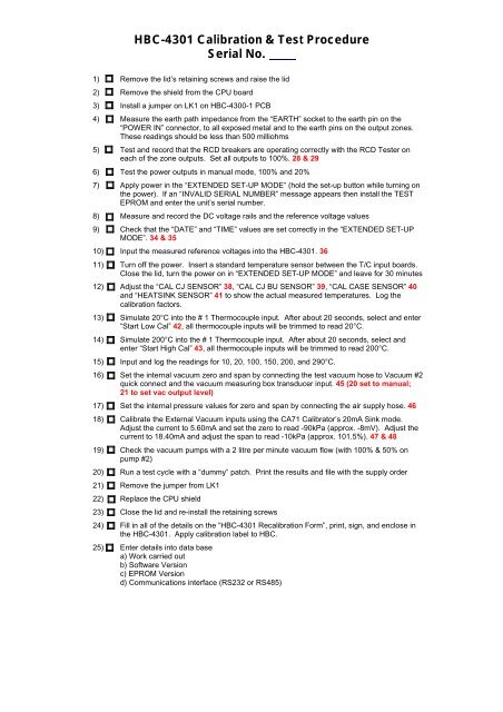
<strong>HBC</strong>-4301 <strong>Calibration</strong> & <strong>Test</strong> <strong>Procedure</strong><br />
Serial No.<br />
1) Remove the lid’s retaining screws and raise the lid<br />
2) Remove the shield from the CPU board<br />
3) Install a jumper on LK1 on <strong>HBC</strong>-4300-1 PCB<br />
4) Measure the earth path impedance from the “EARTH” socket to the earth pin on the<br />
“POWER IN” connector, to all exposed metal and to the earth pins on the output zones.<br />
These readings should be less than 500 milliohms<br />
5) <strong>Test</strong> and record that the RCD breakers are operating correctly with the RCD <strong>Test</strong>er on<br />
each of the zone outputs. Set all outputs to 100%. 28 & 29<br />
6) <strong>Test</strong> the power outputs in manual mode, 100% and 20%<br />
7) Apply power in the “EXTENDED SET-UP MODE” (hold the set-up button while turning on<br />
the power). If an “INVALID SERIAL NUMBER” message appears then install the TEST<br />
EPROM and enter the unit’s serial number.<br />
8) Measure and record the DC voltage rails and the reference voltage values<br />
9) Check that the “DATE” and “TIME” values are set correctly in the “EXTENDED SET-UP<br />
MODE”. 34 & 35<br />
10) Input the measured reference voltages into the <strong>HBC</strong>-4301. 36<br />
11) Turn off the power. Insert a standard temperature sensor between the T/C input boards.<br />
Close the lid, turn the power on in “EXTENDED SET-UP MODE” and leave for 30 minutes<br />
12) Adjust the “CAL CJ SENSOR” 38, “CAL CJ BU SENSOR” 39, “CAL CASE SENSOR” 40<br />
and “HEATSINK SENSOR” 41 to show the actual measured temperatures. Log the<br />
calibration factors.<br />
13) Simulate 20°C into the # 1 Thermocouple input. After about 20 seconds, select and enter<br />
“Start Low Cal” 42, all thermocouple inputs will be trimmed to read 20°C.<br />
14) Simulate 200°C into the # 1 Thermocouple input. After about 20 seconds, select and<br />
enter “Start High Cal” 43, all thermocouple inputs will be trimmed to read 200°C.<br />
15) Input and log the readings for 10, 20, 100, 150, 200, and 290°C.<br />
16) Set the internal vacuum zero and span by connecting the test vacuum hose to Vacuum #2<br />
quick connect and the vacuum measuring box transducer input. 45 (20 set to manual;<br />
21 to set vac output level)<br />
17) Set the internal pressure values for zero and span by connecting the air supply hose. 46<br />
18) Calibrate the External Vacuum inputs using the CA71 Calibrator’s 20mA Sink mode.<br />
Adjust the current to 5.60mA and set the zero to read -90kPa (approx. -8mV). Adjust the<br />
current to 18.40mA and adjust the span to read -10kPa (approx. 101.5%). 47 & 48<br />
19) Check the vacuum pumps with a 2 litre per minute vacuum flow (with 100% & 50% on<br />
pump #2)<br />
20) Run a test cycle with a “dummy” patch. Print the results and file with the supply order<br />
21) Remove the jumper from LK1<br />
22) Replace the CPU shield<br />
23) Close the lid and re-install the retaining screws<br />
24) Fill in all of the details on the “<strong>HBC</strong>-4301 Recalibration <strong>Form</strong>”, print, sign, and enclose in<br />
the <strong>HBC</strong>-4301. Apply calibration label to <strong>HBC</strong>.<br />
25) Enter details into data base<br />
a) Work carried out<br />
b) Software Version<br />
c) EPROM Version<br />
d) Communications interface (RS232 or RS485)
<strong>HBC</strong>-4301 <strong>Calibration</strong> <strong>Form</strong><br />
Customer:<br />
Location:<br />
Comms:<br />
Date:<br />
Serial No.:<br />
Order No.:<br />
Operation Zone 1 Zone 2 Zone 3<br />
RCD trip tests<br />
Trip Current (< 30mA)<br />
Trip Time (< 300ms)<br />
Voltages<br />
<strong>Calibration</strong><br />
VCC Power supply 5VDC<br />
Earth Continuity (< 500mO)<br />
Power supply +12VDC<br />
Cold start (new EPROM)<br />
Power supply -12VDC - Enter date/time<br />
TC Reference (12.3mV ±0.3)<br />
Enter reference voltages<br />
Reference #1 (53.6mV ±2.0) Cal at 20 °C<br />
Reference #2 (481mV ±10) Cal at 200 °C<br />
Accuracy (after calibration)<br />
Measured ambient Temp °C<br />
CJ temperature °C O/S set to- ±4<br />
CJ BU temperature °C O/S set to- ±4<br />
Case temperature °C O/S set to- ±4<br />
H/S temperature °C O/S set to- ±6<br />
Temperature checked at … 10 20 100 150 200 290<br />
(±1 °C)<br />
Int. vacuum transducer O/S Span Zero test (0kPa ±3) Span test (-75kPa ±3)<br />
-<br />
Int. pressure transducer O/S Span Zero test (0kPa ±10) Span test (460kPa ±20)<br />
Ext vac transducer #1 Zero Span -10kPa test -90kPa test<br />
-90 & -10 kPa, ±3 % - -<br />
Ext vac transducer #2 Zero Span -10kPa test -90kPa test<br />
-90 & -10 kPa, ±3 % - -<br />
Inlet Pressure 460kPa<br />
kPa<br />
Vac pump #2 manual control, leak rate 2 l/min 100% - -73 ±5<br />
Vac pump #2 manual control, leak rate 2 l/min 50% - -70 ±5<br />
Vac pump #1, leak rate 2 l/min 100% - -70 ±5<br />
Additional Checks<br />
Temperature cycle run successful<br />
Final check<br />
EPROM version<br />
Audible Alarm Enabled<br />
Shield Installed<br />
<strong>Calibration</strong> Label<br />
Signed<br />
This is to certify that the above <strong>HBC</strong>-4301 was calibrated and<br />
checked by ________________ on ______________. The above<br />
<strong>HBC</strong>-4301 is operating in accordance and within specifications.


