

Disassembly of a 1232 Probe.pdf - Novatech Controls
Disassembly of a 1232 Probe.pdf - Novatech Controls
Disassembly of a 1232 Probe.pdf - Novatech Controls

You also want an ePaper? Increase the reach of your titles
YUMPU automatically turns print PDFs into web optimized ePapers that Google loves.
Service Note SN-003<br />
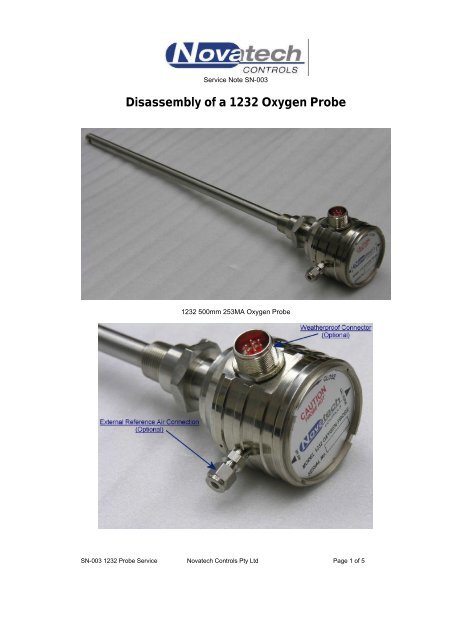
<strong>Disassembly</strong> <strong>of</strong> a <strong>1232</strong> Oxygen <strong>Probe</strong><br />
<strong>1232</strong> 500mm 253MA Oxygen <strong>Probe</strong><br />
SN-003 <strong>1232</strong> <strong>Probe</strong> Service <strong>Novatech</strong> <strong>Controls</strong> Pty Ltd Page 1 <strong>of</strong> 5
1.0 DISASSEMBLY PROCEDURE<br />
1.1 Remove the calibration port fitting. This could be 1/8” NPT plug or male connector if purge air or<br />
calibration gas is used.<br />
1.2 Remove the castellated lid on the probe head. Use the shank <strong>of</strong> a suitable spanner or a square<br />
cross-section bar<br />
SN-003 <strong>1232</strong> <strong>Probe</strong> Service <strong>Novatech</strong> <strong>Controls</strong> Pty Ltd Page 2 <strong>of</strong> 5
1.3 Unplug the wiring from the head connector. These are the probe positive, thermocouple positive<br />
and thermocouple negative. The thermocouple is optional in the <strong>1232</strong> probe.<br />
1.4 Remove the silicon tube from the hypodermic that runs through the head connector or from the<br />
barb on the external reference air connector. (Gently work the silicon tube to get this <strong>of</strong>f)<br />
SN-003 <strong>1232</strong> <strong>Probe</strong> Service <strong>Novatech</strong> <strong>Controls</strong> Pty Ltd Page 3 <strong>of</strong> 5
1.5 Remove the earthed wire inside the head (O 2 –ve) and remove the head connector.<br />
1.6 Evenly remove the two nylock nuts holding down the compression plate. This will remove the<br />
spring loading on the four-bore insulator and the sensor.<br />
SN-003 <strong>1232</strong> <strong>Probe</strong> Service <strong>Novatech</strong> <strong>Controls</strong> Pty Ltd Page 4 <strong>of</strong> 5
1.7 Carefully remove the four-bore insulator containing the thermocouple and probe positive<br />
conductor.<br />
a) Inspect for damage to the ceramic insulator.<br />
b) Check the conductors for damage or oxidation.<br />
1.8 Remove the sensor compression spring from the gland on top <strong>of</strong> the sensor.<br />
1.9 Using long nose pliers, carefully remove the sensor gland and the sensor from the probe sheath.<br />
a) Inspect for damage<br />
b) Check the state <strong>of</strong> the sensor’s catalytic electrode material<br />
Reverse this procedure for reassembly.<br />
Note: Wipe a small amount <strong>of</strong> o-ring grease (such as Molykote FS3451) around the top <strong>of</strong> the sensor<br />
and outer o-ring on the sensor gland before re-installing the sensor and gland.<br />
SN-003 <strong>1232</strong> <strong>Probe</strong> Service <strong>Novatech</strong> <strong>Controls</strong> Pty Ltd Page 5 <strong>of</strong> 5


