
You also want an ePaper? Increase the reach of your titles
YUMPU automatically turns print PDFs into web optimized ePapers that Google loves.
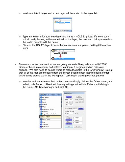
◦ Next select Add Layer and a new layer will be added to the layer list.<br />
◦ Type in the name for your new layer and name it HOLES. (Note: If the cursor is<br />
not all ready flashing in the name field for the layer, the user can click+pause+click<br />
the text in order to edit the name.)<br />
◦ Click on the HOLES layer icon so that a check mark appears, making it the active<br />
layer.<br />
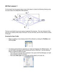
• From our print we can see that we are going to create 10 equally spaced 0.2500”<br />
diameter holes in a circular bolt pattern, starting at 0 degrees and no holes are<br />
skipped. We also need to decide where to place the holes in the CAD window. Being<br />
that all of the radii are measure from the center it seems best that we should center<br />
this drawing around 0,0 in the workspace. Let's begin drawing our bolt pattern.<br />
◦ In order to draw a circular bolt pattern, we can simply click on the Other menu, and<br />
select Hole Pattern. Use the following settings in the Hole Pattern edit dialog in<br />
the Data-<strong>CAM</strong> Tree Manager and click OK: