Version 23 BobNEST Lesson - BobCAD-CAM
Version 23 BobNEST Lesson - BobCAD-CAM
Version 23 BobNEST Lesson - BobCAD-CAM

Create successful ePaper yourself
Turn your PDF publications into a flip-book with our unique Google optimized e-Paper software.
<strong>Version</strong> <strong>23</strong> <strong>BobNEST</strong> <strong>Lesson</strong><br />
<strong>Version</strong> <strong>23</strong> <strong>BobNEST</strong> <strong>Lesson</strong><br />
This tutorial is designed to highlight some of the key areas of the <strong>BobCAD</strong>-<strong>CAM</strong> V<strong>23</strong>’s <strong>BobNEST</strong><br />
module. In this example, we will be simply profile cutting the parts from the sheet.<br />
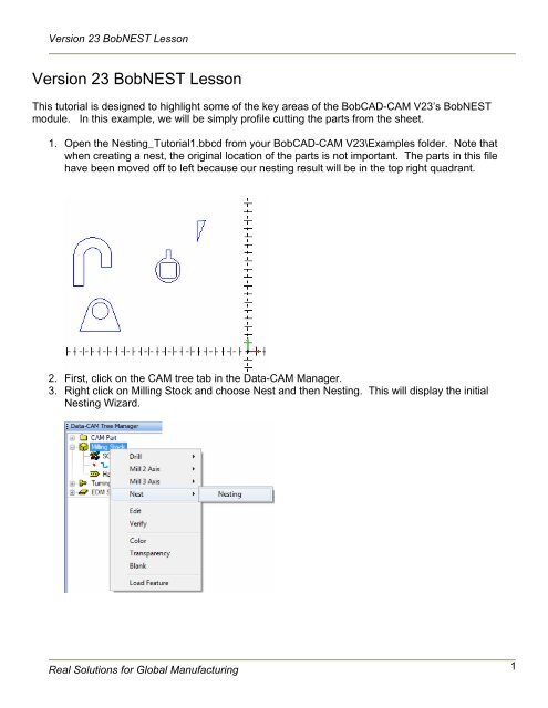
1. Open the Nesting_Tutorial1.bbcd from your <strong>BobCAD</strong>-<strong>CAM</strong> V<strong>23</strong>\Examples folder. Note that<br />
when creating a nest, the original location of the parts is not important. The parts in this file<br />
have been moved off to left because our nesting result will be in the top right quadrant.<br />
2. First, click on the <strong>CAM</strong> tree tab in the Data-<strong>CAM</strong> Manager.<br />
3. Right click on Milling Stock and choose Nest and then Nesting. This will display the initial<br />
Nesting Wizard.<br />
Real Solutions for Global Manufacturing 1
<strong>Version</strong> <strong>23</strong> <strong>BobNEST</strong> <strong>Lesson</strong><br />
4. The first page of the Nesting Wizard allows the user to associate their parts to the Nesting<br />
Feature. In this example, all of the parts to be nested are contained in the original part file, so<br />
we will simply be selecting them using the Pick Geometry option. If the parts that are to be<br />
nested are all contained in separate part files, the user can choose the Browse option to find<br />
the folder location and add the separate part files to the Nesting Feature.<br />
5. Click the Pick Geometry button. The Nesting Wizard will disappear, and the software will be<br />
placed into selection mode for selecting the parts.<br />
6. Click and drag a window around all of the parts in the workspace.<br />
Real Solutions for Global Manufacturing 2
<strong>Version</strong> <strong>23</strong> <strong>BobNEST</strong> <strong>Lesson</strong><br />
7. Once all of the parts are highlighted, right click in the workspace and choose OK to complete<br />
the part selection.<br />
8. The Nesting Wizard will reappear, and the four separate parts will be listed in the Selected<br />
Parts and Files area of the dialog as shown below.<br />
Real Solutions for Global Manufacturing 3
<strong>Version</strong> <strong>23</strong> <strong>BobNEST</strong> <strong>Lesson</strong><br />
9. Now that the parts are associated with the Nesting Feature, click the Next button to move to<br />
the Parts Parameters page.<br />
Notice that each part selected is listed with information regarding the part. The user can click<br />
on each part to set the part type, priority, and quantity of each part.<br />
10. For Part 1 change the Priority to 2 so that we will guarantee all the other parts will be fit into the<br />
sheet first (Lower numbered priority levels are used first). This part will be used just to fill up<br />
the extra area of the sheet after the other parts are nested. Change the quantity to 200.<br />
Real Solutions for Global Manufacturing 4
<strong>Version</strong> <strong>23</strong> <strong>BobNEST</strong> <strong>Lesson</strong><br />
11. Click on Part 2 in the part list, and change the quantity to 35. Repeat this step setting the<br />
quantity for Part 3 to 32 and Part 4 to 24.<br />
12. Now that the number of each part has been defined, click the Next button to move to the<br />
Select Sheets page.<br />
Real Solutions for Global Manufacturing 5
<strong>Version</strong> <strong>23</strong> <strong>BobNEST</strong> <strong>Lesson</strong><br />
13. For this example we are going to be using one 48 x 36 sheet. Simply change the length to 48<br />
and the width to 36. The reference point can be left alone.<br />
14. Now that the sheet is defined, click the Next button to move to the Nesting Parameters page.<br />
Real Solutions for Global Manufacturing 6
<strong>Version</strong> <strong>23</strong> <strong>BobNEST</strong> <strong>Lesson</strong><br />
15. In this example, we will want to leave Generate tool path before nesting checked, since we do<br />
want to create the tool path for this nested result. Otherwise the nesting system will only nest<br />
the parts and will not generate any tool path.<br />
The Cutting Direction, Start/Direction, and Toolpath Pattern can be left at the defaults.<br />
16. The Machining Order group can be ignored since we are simply profiling in this example, as<br />
we have no holes or Dadoes.<br />
17. The Cutting Order can be left to By Part, meaning each part will be completely cut from the<br />
stock before moving to the next part. Inner profiles will also be cut before the outer profile of<br />
the part. If we were to switch to By Sheet, then all of the inner profiles will be cut for the entire<br />
sheet, before returning to cut the outside profiles of each part.<br />
18. For this example we will leave the Bridge Distance set to 0, because we want to nest these<br />
parts as closely together as we can.<br />
19. Set the Stock Margin to 0.5000 to leave a margin around the outside of the sheet.<br />
20. Now that our Nesting Parameters are complete, click the Next button to move to the tool<br />
definition page.<br />
Real Solutions for Global Manufacturing 7
<strong>Version</strong> <strong>23</strong> <strong>BobNEST</strong> <strong>Lesson</strong><br />
21. In this example we are going to use a 0.125 profiling tool. This would be applicable to<br />
Laser/Plasma/Waterjet machining. The user can click the Edit Advanced button to display the<br />
normal Profile machining dialog where they can edit things such as further tool information,<br />
feeds and speeds, etc. Seeing that we have no Dadoes or drilling occurring (common to router<br />
nesting), we can simply ignore these fields.<br />
22. Simply change the Tool Diameter to 0.125 and click Finish.<br />
Real Solutions for Global Manufacturing 8
<strong>Version</strong> <strong>23</strong> <strong>BobNEST</strong> <strong>Lesson</strong><br />
<strong>23</strong>. The Nesting Feature will be added to the <strong>CAM</strong> tree. (Shown expanded below)<br />
24. Right click on the Nest Parts item in the tree to compute the nesting result.<br />
25. The nested result is created.<br />
Real Solutions for Global Manufacturing 9
<strong>Version</strong> <strong>23</strong> <strong>BobNEST</strong> <strong>Lesson</strong><br />
26. At this point the program can be simulated by right clicking on the individual sheet in the <strong>CAM</strong><br />
tree, and choosing Verify to use the internal simulation. If the higher level simulation has been<br />
purchased, the user can choose Virtual CNC to launch the simulation of each sheet inside of<br />
the Predator Virtual CNC software.<br />
Real Solutions for Global Manufacturing 10
<strong>Version</strong> <strong>23</strong> <strong>BobNEST</strong> <strong>Lesson</strong><br />
27. The simulated sheet will looks as follows after being processed.<br />
Understanding the Nesting Feature<br />
After working through the Nesting Wizard, if any changes are to be made to the nesting result, the<br />
Nesting Feature will need to be edited. The following steps will walk through the most common edits<br />
that will need to be made.<br />
1. First right click on the Nest Parts item of the <strong>CAM</strong> tree and click Edit.<br />
Real Solutions for Global Manufacturing 11
<strong>Version</strong> <strong>23</strong> <strong>BobNEST</strong> <strong>Lesson</strong><br />
2. The Nesting Edit dialog will appear which will allow things such as default approach and entry<br />
parameters, number of parts, part priority, as well as the other nesting parameters.<br />
3. Click OK on this dialog, as we do not wish to make any changes at this time. Next right click<br />
on the Sheets item and choose Show Leftover.<br />
4. The Leftover dialog will be displayed. Notice that we have 111 of the small triangular parts<br />
that did not fit on the nested sheet.<br />
Real Solutions for Global Manufacturing 12
<strong>Version</strong> <strong>23</strong> <strong>BobNEST</strong> <strong>Lesson</strong><br />
5. In order to have all of our parts nested we will need to add another sheet. This can be<br />
accomplished by right clicking on the Sheets item and choosing Add Sheet.<br />
6. A new sheet will be added to the <strong>CAM</strong> tree. The new sheet added will match the dimensions<br />
of the previous sheet in the sheet list. If the sheet size needs to be modified, the user can<br />
simply right click on the sheet item and choose edit.<br />
Real Solutions for Global Manufacturing 13
<strong>Version</strong> <strong>23</strong> <strong>BobNEST</strong> <strong>Lesson</strong><br />
7. Next simply re-compute the Nest in order to utilize the newly added sheet by right clicking on<br />
Nest Parts and choosing Compute Toolpath.<br />
The Nesting Result:<br />
8. Since the two sheets are overlapping, next we will blank the first sheet to see the result of the<br />
second sheet. To do this, right click on Sheet 1 and choose Blank Sheet.<br />
Real Solutions for Global Manufacturing 14
<strong>Version</strong> <strong>23</strong> <strong>BobNEST</strong> <strong>Lesson</strong><br />
9. Now the second sheet is the only one being displayed, and we can see that the other 111<br />
parts have now been nested on a new sheet.<br />
10. For this example we only want to work with one sheet, so right click on Sheet 2 and click<br />
Remove.<br />
Real Solutions for Global Manufacturing 15
<strong>Version</strong> <strong>23</strong> <strong>BobNEST</strong> <strong>Lesson</strong><br />
11. After removing a sheet it is always a good idea to re-compute the nesting result. Sheet 1 will<br />
also need to be un-blanked by right clicking on the Sheet 1 item and clicking Blank Sheet once<br />
again. Go ahead and perform these steps, and the Nesting result in the CAD window should<br />
look as follows:<br />
12. The final step after any tool path creation process is to create the G-Code for the machine.<br />
The user can post the program by right clicking on Milling Tools located under the <strong>CAM</strong> Part<br />
item, or by right clicking on an individual sheet to post the program for the just the sheet. One<br />
important thing to note is that when clicking Post under the Milling Tools item, the entire<br />
program for all sheets will be posted in one large program. Since in this example we only<br />
have one sheet, it makes no difference which method is chosen.<br />
That concludes this tutorial.<br />
Real Solutions for Global Manufacturing 16