
Create successful ePaper yourself
Turn your PDF publications into a flip-book with our unique Google optimized e-Paper software.
<strong>2D</strong> <strong>Part</strong> <strong>Lesson</strong> 1<br />
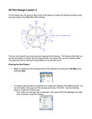
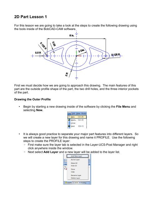
For this lesson we are going to take a look at the steps to create the following drawing using<br />
the tools inside of the <strong>BobCAD</strong>-<strong>CAM</strong> software.<br />
First we must decide how we are going to approach this drawing. The main features of this<br />
part are the outside profile shape of the part, the two drill holes, and the three interior pockets<br />
of the part.<br />
Drawing the Outer Profile<br />
• Begin by starting a new drawing inside of the software by clicking the File Menu and<br />
selecting New.<br />
• It is always good practice to separate your major part features into different layers. So<br />
we will create a new layer for this drawing and name it PROFILE. Use the following<br />
steps to create the PROFILE layer:<br />
◦ First make sure the layer tab is selected in the Layer-UCS-Post Manager and right<br />
click anywhere inside the window.<br />
◦ Next select Add Layer and a new layer will be added to the layer list.
◦ Type in the name for your new layer and name it PROFILE. (Note: If the cursor is<br />
not all ready flashing in the name field for the layer, the user can click+pause+click<br />
the text in order to edit the name.)<br />
◦ Click on the PROFILE layer icon so that a check mark appears, making it the active<br />
layer.<br />
• Begin the outer profile by drawing the 3 main arcs that comprise the outside shape.<br />
<strong>Part</strong>s of these arcs will also be used for the internal pockets later on in the lesson.<br />
◦ Select the Arc Menu and select Arc Coordinates.<br />
▪ Enter 2 in the Radius field<br />
▪ Set the Center X, Center Y, and Center Z fields to 0.0000<br />
▪ Enter 0.0000 in the Start Angle.<br />
▪ Enter 360.000 in the End Angle to draw a complete circle.<br />
▪ Click OK to create the arc in the workspace
▪ Change the Center X to -4.0<br />
▪ Change the Radius to 0.5<br />
▪ Click the OK button to create the next arc in the workspace<br />
▪ Change the Center X to 4.0<br />
▪ Click the OK button to create the next arc in the workspace<br />
• Next we want to add in the four tangent lines that connect these three arcs to finish the<br />
outside shape.<br />
◦ Select the Line Menu and select Tangent<br />
◦ Click the arcs in the following locations in the order shown below to create the 4<br />
tangent lines.
Drawing the Internal Pockets<br />
• Before beginning drawing the interior pockets of the part, start by creating a new layer,<br />
naming the layer POCKETS, and making this the active layer. The steps for creating a<br />
layer can be found in the prior section Drawing the Outside Profile.<br />
• Next we need to finish completing the internal pockets of the part. To do this we first<br />
need to add the linear edges of the pockets<br />
◦ Select the Line Menu and select Parallel<br />
▪<br />
▪<br />
Enter 0.25 in the Distance field because we can see in the above print that the<br />
pocket boundary is 0.25” away from the outside profile.<br />
Click the top left line in the workspace and then move the cursor towards the<br />
inside of the part and click again to place the parallel line.
▪<br />
Repeat the last step for the last 3 lines that make up the outside profile, placing<br />
the lines to the inside of the part. The result should look as follows:<br />
• Next we will need to break some of the entities at their intersections in the workspace<br />
in order to complete the necessary fillets.<br />
◦ Select the Utilities Menu and click Break and select Many<br />
▪<br />
Click and drag a window around all of the entities in the workspace.<br />
▪<br />
Next click the 4 lines we made in the previous step so that they are not selected<br />
because we do not need to break these entities, and by not breaking them we<br />
will avoid having to delete a lot of extra entities later on.<br />
▪<br />
Complete the break function by right clicking in the workspace and selecting<br />
OK.
◦ Select the Arc Menu and select Fillet<br />
▪<br />
▪<br />
Enter 0.125 in the Radius field<br />
Click the entities shown below in the order shown to complete the necessary<br />
fillets to complete the inside pockets.<br />
• Finally we can add the large circular pocket at the center of the part.<br />
◦ Start by clicking the Arc Menu and selecting Arc Snap.<br />
▪<br />
▪<br />
Enter 1.5 for the Radius<br />
Leave the Start Angle and End Angle at 0.000 and 360.000 respectively.<br />
◦ Next while holding the Shift key down on your keyboard select the arc at the top of<br />
the part. This will activate the snap points allowing the user to select the arc center.<br />
Click the center snap point located at the origin to create the new arc. The result<br />
should look as follows:
Drawing the Drill Holes<br />
• Before beginning drawing the outside profile of the part, start by creating a new layer,<br />
naming the layer HOLES, and making this the active layer. The steps for creating a<br />
layer can be found in the prior section Drawing the Outer Profile.<br />
• As we see in the print, this part requires two 0.25” diameter holes at each edge of the<br />
part.<br />
◦ Start by clicking the Arc Menu and selecting Arc Snap if the function is not all<br />
ready active.<br />
▪<br />
▪<br />
Enter 0.125 for the Radius<br />
Leave the Start Angle and End Angle at 0.000 and 360.000 respectively.<br />
◦ Next while holding the Shift key down on your keyboard select the arc at the far left<br />
of the part. This will activate the snap points allowing the user to select the arc<br />
center. Click the center snap point located at arc center to create the new arc. The<br />
result should look as follows:<br />
◦ Repeat the last step, selecting the arc at the far right to place the final hole<br />
You have completed <strong>2D</strong> <strong>Part</strong> <strong>Lesson</strong> 1!