
Create successful ePaper yourself
Turn your PDF publications into a flip-book with our unique Google optimized e-Paper software.
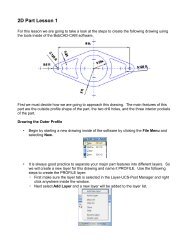
<strong>2D</strong> <strong>Part</strong> <strong>Design</strong> <strong>Lesson</strong> 2<br />
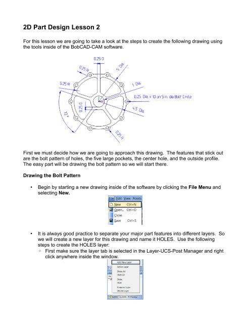
For this lesson we are going to take a look at the steps to create the following drawing using<br />
the tools inside of the <strong>BobCAD</strong>-<strong>CAM</strong> software.<br />
First we must decide how we are going to approach this drawing. The features that stick out<br />
are the bolt pattern of holes, the five large pockets, the center hole, and the outside profile.<br />
The easy part will be drawing the bolt pattern so we will start there.<br />
Drawing the Bolt Pattern<br />
• Begin by starting a new drawing inside of the software by clicking the File Menu and<br />
selecting New.<br />
• It is always good practice to separate your major part features into different layers. So<br />
we will create a new layer for this drawing and name it HOLES. Use the following<br />
steps to create the HOLES layer:<br />
◦ First make sure the layer tab is selected in the Layer-UCS-Post Manager and right<br />
click anywhere inside the window.
◦ Next select Add Layer and a new layer will be added to the layer list.<br />
◦ Type in the name for your new layer and name it HOLES. (Note: If the cursor is<br />
not all ready flashing in the name field for the layer, the user can click+pause+click<br />
the text in order to edit the name.)<br />
◦ Click on the HOLES layer icon so that a check mark appears, making it the active<br />
layer.<br />
• From our print we can see that we are going to create 10 equally spaced 0.2500”<br />
diameter holes in a circular bolt pattern, starting at 0 degrees and no holes are<br />
skipped. We also need to decide where to place the holes in the CAD window. Being<br />
that all of the radii are measure from the center it seems best that we should center<br />
this drawing around 0,0 in the workspace. Let's begin drawing our bolt pattern.<br />
◦ In order to draw a circular bolt pattern, we can simply click on the Other menu, and<br />
select Hole Pattern. Use the following settings in the Hole Pattern edit dialog in<br />
the Data-<strong>CAM</strong> Tree Manager and click OK:
• That completes the hole pattern. Next we will move on to drawing the outside profile.<br />
Drawing the Outside Profile<br />
• Before beginning drawing the outside profile of the part, start by creating a new layer,<br />
naming the layer PROFILE, and making this the active layer. The steps for creating a<br />
layer can be found in the prior section Drawing the Bolt Pattern<br />
• We can see from the print that there is are ten 0.25 radius arcs around all of the holes<br />
that also share the same center point as the hole itself, all connected by 5” diameter<br />
arcs, with 0.25” radius fillets in between. Noticing that all of these shapes are exactly<br />
the same, we will draw one, and use the Rotate command to save a lot of drawing<br />
time.<br />
◦ First lets draw the 0.25 radius arc that shares the same center as the hole set at 0<br />
degrees.<br />
▪ Start by clicking the Arc Menu and selecting Arc Snap.<br />
• Enter 0.25 for the Radius<br />
• Leave the Start Angle and End Angle at 0.000 and 360.000 respectively.<br />
▪<br />
Next while holding the Shift key down on your keyboard select the farthest right<br />
hole in the bolt circle. This will activate the snap points allowing the user to<br />
select the arc center. Click the center snap point to create the new arc. The<br />
result should look as follows:
◦ Next lets draw the 5” diameter circle centered around 0,0.<br />
▪ Click on the Arc Menu and select Arc Coordinates.<br />
▪<br />
In the fields enter the following values and click OK:<br />
◦ Next we need to get rid of the extra geometry we have in the workspace. In order<br />
to do this we are going to need to break the arcs in the workspace.<br />
▪ Click the Utilities Menu and click Break and select Many.<br />
• Select the two arcs we have just created and right click and select OK.<br />
(Note: Instead of right clicking and selecting OK, the user can also press the<br />
space bar to finalize their selection)
◦ Now that our two arcs have been broken at their intersections, we can delete the<br />
unnecessary geometry from the workspace.<br />
▪ With the Break Many function still active, select the shown below and press the<br />
delete key on the keyboard.<br />
▪<br />
Finally click the Cancel button to cancel the Break Many function.<br />
◦ Next we need to add our fillets between the two arcs we have created for the<br />
outside profile.<br />
▪ To do this, click the Arc Menu and select Fillet.<br />
▪<br />
Enter 0.25” in the Radius field and click the two arcs in the following locations:<br />
◦ That completes are desired shape so now we can use the Rotate function to create<br />
the other 9 copies of this geometry.<br />
▪<br />
Start by clicking the Utilities Menu and selecting the Rotate function.<br />
• We know that there are 10 equally spaced copies of this geometry, so to<br />
determine angle to rotate enter 360/10 into the Z field because we want to<br />
rotate around the Z axis.<br />
• Click the Copies button to enable the copies field and enter 9 into the field.<br />
We want to create 9 copies because we want 10 of these shapes and we all<br />
ready have one.
• In the Origin box, choose Enter and leave all fields set to 0.0000 since we<br />
will be rotating around the origin.<br />
• Next we need to select the 0.25” radius arc entities we wish to copy. Select<br />
the arcs shown below and right click in the workspace and select OK<br />
• Finally press OK in the Data Manager to complete the rotate command. The<br />
result should look as follows:<br />
◦ The final step to completing the outside profile is to simply remove the extra<br />
geometry left from the 5” diameter circle by breaking all of the entities at their<br />
intersections.<br />
▪ Click the Utilities Menu and click Break, then select Many function.<br />
▪<br />
▪<br />
We do not want to break any of the holes from our hole pattern, so we can<br />
simply blank this layer by clicking the small black square next to the HOLES<br />
layer in the Layer-UCS-Post Manager.<br />
Now that the HOLES layers is blanked, click and drag a window around
▪<br />
everything in the workspace to select all of the entities. After making sure all of<br />
the visible entities are highlighted, right click in the workspace and click OK.<br />
Finally, highlight the extra entities shown below in the workspace and press the<br />
Delete key on the keyboard to remove the extra entities.<br />
▪ That completes the outside profile for the part. Next we will need to draw the 5<br />
pockets inside of the part. The HOLES layer can also be made visible again by<br />
clicking the square located to the left of the layer name in the Layer-UCS-Post<br />
Manager.<br />
Drawing the Interior Pockets<br />
• Before beginning drawing the interior pockets of the part, start by creating a new layer,<br />
naming the layer POCKETS, and making this the active layer. The steps for creating a<br />
layer can be found in the prior section Drawing the Bolt Pattern<br />
• We have multiples of the same interior shape equally spaced around this part, so again<br />
we are simply going to draw one interior pocket and use the Rotate command to make<br />
the extra copies of this interior pocket.<br />
• To create the outer arc of the pocket select the Arc Menu and select Arc Coordinates.
◦ Enter 2.25 in the Radius field<br />
◦ Set the Center X, Center Y, and Center Z fields to 0.0000<br />
◦ Enter 0.0000 in the Start Angle.<br />
◦ Enter 360.000 in the End Angle to draw a complete circle.<br />
◦ Click OK to create the arc in the workspace<br />
• Next, create the inner arc of the pocket by simply changing the radius field to 0.75 and<br />
clicking OK. We chose 0.75 because as we see in the print, the radius of the inner arc<br />
of the pocket is 0.25 inches bigger than the 0.5 inch radius arc in the center of the part.<br />
• Next to create the edges of the pocket we will first draw a construction line. Start by<br />
clicking on the Line Menu and selecting Join.<br />
◦ To draw the reference line, first click the top of the inner arc followed by a second<br />
click on the top of the outer arc to complete the line.
• In our print, notice that the ribs between the pockets are going to be 0.25” wide, so we<br />
will need to create a parallel line half this distance from this center line we had just<br />
created.<br />
◦ First click the Line Menu and select Parallel<br />
▪<br />
▪<br />
Enter 0.125 in the Distance field since this is half of the rib.<br />
Click the reference line we had just created and click anywhere in the<br />
workspace to the left of this reference line to create the parallel line.<br />
▪<br />
Next repeat this step creating a parallel line to the right.<br />
• Next zoom into the area near the end of these newly created lines and the inner arc<br />
and notice the gap between these entities. We will need to fill this gap by using the<br />
Trim function.<br />
◦ Select the Utilities Menu, click Trim and select One Entity.
◦ First click the end of the line near the inner arc<br />
◦ Next click the inner arc to complete the function. The line will automatically extend<br />
to the inside arc.<br />
◦ Repeat these steps for the other parallel line we created.<br />
◦ Repeat these steps again, except now trim the rib edge lines to larger outer arc of<br />
the pocket.<br />
• Next we need to create the opposite side of the pocket.<br />
◦ Select the Utilities Menu and select Rotate.<br />
▪<br />
▪<br />
▪<br />
▪<br />
▪<br />
▪<br />
Enter 360/5 in the Z field because we<br />
are creating 5 equally spaced pockets.<br />
Entering 360/5 will give us the 72<br />
degrees we are looking to achieve.<br />
Select Copy and enter 1 in the field.<br />
Under Origin, choose Enter<br />
Enter -0.125 in the X field.<br />
Enter 0.125 in the Y field.<br />
Enter 0.0 in the Z field.<br />
◦ Select the right edge of the rib we created<br />
and right click in the workspace and select<br />
OK.
◦ Finally click OK in the Data Manager to complete the Rotate command.<br />
• Now that the outside perimeter of the pocket is created, we need to get rid of the extra<br />
geometry by breaking the entities at the intersections.<br />
◦ Select the Utilities Menu and select Break and click Many.<br />
◦ Click the two edge lines of the pocket and the inner and outer circle that comprise<br />
the pocket and right click in the workspace and select OK.<br />
◦ Finally highlight the entities shown below and press the Delete key on the keyboard<br />
to remove the unnecessary entities. (Note: In the event that the entities shown<br />
cannot be highlighted the same way as shown below, it will be necessary to go<br />
back and make sure the rib edges were trimmed properly to the inner and outer<br />
arcs, and repeat the break many function)<br />
• To finish the pocket we simply need to add the 0.25” radius fillets to all of the corners.<br />
◦ Select the Arc Menu and click Fillet
▪<br />
▪<br />
Enter 0.25 in the Radius field<br />
Click the entities in the order shown below to create all of the necessary fillets.<br />
• Now to complete all of the interior pockets we need to rotate the shape around the<br />
origin creating 4 copies.<br />
◦ Select the Utilities Menu and select Rotate.<br />
▪ Enter 360/5 in the Z field because we are creating 5 equally spaced pockets.<br />
Entering 360/5 will give us the 72 degrees we are looking to achieve.<br />
▪ Select Copy and enter 4 in the field.<br />
▪ Under Origin, choose Enter and set all of the fields to 0.0000<br />
◦ While holding the Shift key on your keyboard click on one of the entities of the<br />
interior shape to highlight the entire chain and then right click in the workspace and<br />
select OK.
◦ Complete the function by clicking the OK button in the Data Manager.<br />
• The last step to completing this part will be to draw the final circle at the center of the<br />
part.<br />
◦ Select the Arc Menu and select Arc Coordinates.<br />
▪ Enter 0.5 in the Radius field<br />
▪ Set the Center X, Center Y, and Center Z fields to 0.0000<br />
▪ Enter 0.0000 in the Start Angle<br />
▪ Enter 360.000 in the End Angle to draw a complete circle.<br />
▪ Click OK to create the arc in the workspace<br />
You have completed <strong>2D</strong> <strong>Part</strong> <strong>Lesson</strong> 2!