EP5 Electro-pneumatic Positioner - Coulton Instrumentation
EP5 Electro-pneumatic Positioner - Coulton Instrumentation
EP5 Electro-pneumatic Positioner - Coulton Instrumentation

You also want an ePaper? Increase the reach of your titles
YUMPU automatically turns print PDFs into web optimized ePapers that Google loves.
<strong>EP5</strong> <strong>Electro</strong><strong>pneumatic</strong> <strong>Positioner</strong><br />
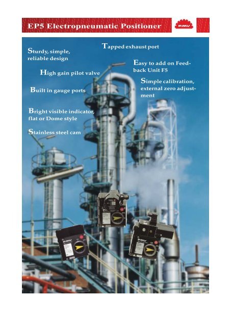
Sturdy, simple,<br />
reliable design<br />
High gain pilot valve<br />
Built in gauge ports<br />
Tapped exhaust port<br />
Easy to add on Feedback<br />
Unit F5<br />
Simple calibration,<br />
external zero adjustment<br />
Bright visible indicator,<br />
flat or Dome style<br />
Stainless steel cam
General<br />
The <strong>EP5</strong> electro<strong>pneumatic</strong> positioner is<br />
adapted from the PMV P5 <strong>pneumatic</strong> positioner.<br />
This compact and sturdy unit is designed for maximum<br />
performance in all types of environ- ments. The <strong>EP5</strong> is available in<br />
Standard, Intrinsically Safe, Explosion Proof and Fail Freeze<br />
versions. A modular feedback unit F5 allows for the addition of<br />
limit switches and/or position transmitters, without additional<br />
mounting brackets.<br />
Other features include: replaceable filter,<br />
gauge ports, dampers, tapped exhaust port for venting of supply<br />
media, external zero adjustment and completely sealed cover.<br />
Simple<br />
Filter plug<br />
I/P converter<br />
I/P converter<br />
I/P converter<br />
Gauge ports<br />
Simple<br />
cam<br />
locking<br />
High Performance<br />
or Low bleed<br />
Spool Valve Simple calibration Stainless Cam<br />
Linear<br />
Equal percent<br />
Square root<br />
Customized
Modular<br />
<strong>EP5</strong>-EX<br />
<strong>EP5</strong>-EX<br />
F5-EX<br />
H5<br />
<strong>EP5</strong>-FS<br />
<strong>EP5</strong>-IS<br />
<strong>EP5</strong><br />
<strong>EP5</strong>-EX<br />
<strong>EP5</strong>-IS<br />
<strong>EP5</strong>-IS<br />
F5-IS<br />
For all normal applications<br />
Explosion Proof<br />
Intrinsically Safe<br />
<strong>EP5</strong><br />
<strong>EP5</strong>-FS Fail Freeze*<br />
* See PMV datasheet 23746<br />
Explosion proof I/P module<br />
Standard or I/S<br />
I/P-converter module<br />
<strong>EP5</strong><br />
Fail Freeze I/P<br />
<strong>EP5</strong><br />
<strong>EP5</strong><br />
Dome<br />
<strong>EP5</strong>-EX indicator<br />
<strong>EP5</strong>-EX <strong>EP5</strong>-IS<br />
Gauges<br />
<strong>EP5</strong>-IS <strong>EP5</strong>-FS<br />
<strong>EP5</strong>-FS<br />
P5 <strong>pneumatic</strong> positioner<br />
For all normal applications<br />
For Explosion all normal Proof applications<br />
Mounting<br />
Explosion Intrinsically Proof Safe<br />
Intrinsically Fail place* Safe<br />
Spindles<br />
Fail in place*<br />
adapter plate<br />
Mounting bracket<br />
F5 EX<br />
F5 feedback module
Technical Specifications<br />
Technical Deadband Specifications<br />
≤ 0.15%<br />
Input signal<br />
4-20mA<br />
Linearity ≤ 1%*<br />
Hysteresis ≤ 0.75%*<br />
Repeatability ≤ 0.5%*<br />
Air supply<br />
Connector threads<br />
Gauge threads<br />
Conduit entry<br />
Terminals<br />
Max 1 MPa/150 Psi, Oil, water and dustfree<br />
Min 0.14 MPa/21 Psi<br />
1/4"NPT or G (BSP)<br />
1/8" NPT or G (BSP)<br />
1/2" NPT or PG 13.5 (M20)<br />
2.5 mm 2 (AVG 14) Screw terminals Low Bleed Version<br />
Gain factor at: 600 KPa/87 Psi Min. 1000 Kpa/Kpa Min: 450 KPa/KPa<br />
Min. 66%/% ISA S75.13-1989 Min: 30 %/%<br />
Max. air consumption at supply pressure:<br />
0.2 MPa/29 Psi 6.1 nl/min (0.22 SCFM) 2,7 nl/min (0,1 SCFM)<br />
0.4 MPa/58 Psi 13.6 nl/min (0.48 SCFM) 6,1 nl/min (0,21 SCFM)<br />
0.6 MPa/87 Psi 22 nl/min (0.78 SCFM) 9.9 nl/min (0,35 SCFM)<br />
0.8 MPa/116 Psi 30.5 nl/min (1.08 SCFM) 13,7 nl/min (0,48 SCFM)<br />
1 MPa/145 Psi 39 nl/min (1.38 SCFM) 17,5 nl/min (0,62 SCFM)<br />
Min. air delivery at supply pressure:<br />
0.2 MPa/29 Psi 200 nl/min (6.9 SCFM) 156 nl/min (5,5 SCFM)<br />
0.4 MPa/58 Psi 370 nl/min (12.8 SCFM) 288 nl/min (10,1 SCFM)<br />
0.6 MPa/87 Psi 540 nl/min (18.8 SCFM) 421 nl/min (14,8 SCFM)<br />
0.8 MPa/116 Psi 710 nl/min (24.7 SCFM) 553 nl/min (19,4 SCFM)<br />
1 MPa/145 Psi 880 nl/min (30.6 SCFM) 686 nl/min (24 SCFM)<br />
Input impedance<br />
170-260 Ohms at 20°C (71°F)<br />
RFI influence<br />
Not measurable<br />
Capacitance<br />
Negligible<br />
Position sensitivity<br />
None<br />
Supply pressure effect<br />
0.5%/0.1 MPa (15 Psi)<br />
Temperature range<br />
-20°C to +85°C/ (-4F to +185°F)<br />
Low temp option<br />
-40°C to +85°C (-40°F to +185°F)<br />
Weight<br />
1.5 kg/3.4 Ibs<br />
Housing<br />
Die cast aluminum<br />
Surface treatment<br />
ED Epoxy paint, Black<br />
Fasteners<br />
A2/A4 Stainless<br />
Ingress protection IP 66/NEMA 4<br />
Approvals<br />
Cenelec Intrinsically safe EEx ia IIC T4-T6<br />
Flameproof** EEx d IIC T4-T6<br />
FM Intrinsically safe Div.1, Class 1, Group ABCD<br />
Explosion proof** Div 1, Class 1, Group BCD<br />
CSA Intrinsically safe Div. 1, Class 1, Group ABCD<br />
Explosion proof** Div 1, Class 1,2,3 Group BCDEFG<br />
*Percent of full scale<br />
**I/P in round housing
For selection of the feedback-spindle pls see<br />
”Drive shaft dimension drawing” SPNDLS. P5<br />
Dimensional Drawing<br />
1/4" G or NPT<br />
<strong>EP5</strong> Explosion proof version<br />
<strong>EP5</strong> with H5<br />
1/2" or PG 13.5 (M20)<br />
<strong>EP5</strong> Footprint
How to order<br />
1. Model <strong>EP5</strong>XX <strong>EP5</strong> Double acting <strong>pneumatic</strong><br />
<strong>EP5</strong>FS Fail freeze function<br />
<strong>EP5</strong>IS<br />
Intrinsically safe, Cenelec, FM, CSA<br />
<strong>EP5</strong>EU Explosion proof Cenelec<br />
<strong>EP5</strong>US Explosion proof CSA, FM<br />
2. Spool valve HP or LB High performance or Low bleed<br />
3. Air connection N or G NPT 1/4” or G 1/4”<br />
3. Surface treatment U or M Epoxy coating or Tufram<br />
4. Spindle 01, 23 etc 01 to 35. See dwg SPNDLSP_5<br />
5. Cam K01 K01 to K17, K01 = linear 90 deg, standard<br />
6. Front cover PV9DA 90 deg, Direct, arrow indicator<br />
7. Input signal 4 4-20 input<br />
8. Temperature N or Q Nitrile seals –20 deg C,<br />
Q=Silicon seals, -40 deg C<br />
* For 30,45 and 60 deg rotation, change PV9 to PV 3, PV4 or PV6.<br />
Example:<br />
<strong>EP5</strong>XX-HPGU-23K01-PV9DA-3Z<br />
1 2 3 4 5 6 7 8<br />
<strong>Coulton</strong> <strong>Instrumentation</strong> Ltd<br />
17 Somerford Business Park<br />
Christchurch<br />
BH23 3RU<br />
ENGLAND<br />
Tel: +44 (0) 1202 480 303<br />
Fax: +44 (0) 1202 480 808<br />
E-mail: sales@coulton.com<br />
Internet: www.coulton.com<br />
22530/2002.9/Ekvator<br />
Total Chlorine<br />
Free Paper