PXR3 Instruction Manual - Coulton Instrumentation
PXR3 Instruction Manual - Coulton Instrumentation
PXR3 Instruction Manual - Coulton Instrumentation

You also want an ePaper? Increase the reach of your titles
YUMPU automatically turns print PDFs into web optimized ePapers that Google loves.
<strong>Instruction</strong> <strong>Manual</strong>Micro-controller XModel : <strong>PXR3</strong>INP-TN1<strong>PXR3</strong>c-EHead Office11-2, Osaki 1-chome, Shinagawa-ku, Tokyo, 141-0032 JapanSales Div. International Sales Dept.No.1, Fuji-machi, Hino-city, Tokyo, 191-8502 JapanPhone : +81-42-585-6201, 6202Fax : +81-42-585-6187http://www.fic-net.co.jpThank you for your purchasing "Fuji Digital Temperature Controller". Please check that the product is exactly theone you ordered and use it according to the following instructions. (Please refer to a separate operation manual fordetails.) Dealers are cordially requested to ensure the delivery of this <strong>Instruction</strong> <strong>Manual</strong> to hands of the endusers.NOTICEThe contents of this document may be changed in the future without prior notice.We paid the utmost care for the accuracy of the contents. However, we are not liable for direct and indirectdamages resulting from incorrect descriptions, omission of information, and use of information in this document.CONTENTSSafety Precautions ............................................... 3Index ................................................................ 91. Installation/mounting ...................................... 102. Wiring ............................................................. 113. Usage ............................................................. 124. Display and operation .................................... 135. Setting methods of temperatureand parameters ....................................... 141st block parameter ........................................ 142nd block parameter ...................................... 153rd block parameter ....................................... 166. Functions ....................................................... 176-1 ON/OFF control ...................................... 176-2 Auto-tuning.............................................. 186-3 Self-tuning ............................................... 196-4 Alarm function [option] ............................ 216-5 Ramp/soak function [option] ................... 236-6 Communication function [option]............. 246-7 Digital input (DI function) [option] ............ 256-8 Other function ......................................... 266-9 Retransmission function [option] ............. 277. Setting of input type and control algorithm ..... 288. Error indications ............................................. 30[Table 1] Input type code ...................................... 31[Table 2] Input range ............................................ 31[Table 3] Alarm action type code .......................... 32[Table 4] Control output action mode code ........... 33PXR Model Code Cofiguration ............................. 34Specification ......................................................... 35– 1 –
Check of specifications and accessoriesBefore using the controller, check if the type and specifications are as ordered.(A table of Model code configuration is given in Page 33).Check that all of the following accessories are included in the package box.· Temperature controller 1 unit· <strong>Instruction</strong> manual 1 copy· Mounting bracket 1 pce.· Watertight packing 1 pce.· I/V unit (250Ω resistor) 1 pce. (4-20mA DC input type only)The related documentsContentsSpecificationsOperation methodCommunicationfunctionsNameCatalogueMICRO-CONTROLLER X(Model:<strong>PXR3</strong>)OPERATION MANUALCOMMUNICATION FUNCTIONS(MODBUS)INSTRUCTION MANUALCOMMUNICATION FUNCTIONS(Z-ASCII)INSTRUCTION MANUALNo.ECNO:1138ECNO:409INP-TN512642-EINP-TN512644-E– 2 –
Safety PrecautionsBefore using this product, the user is requested to read the following precautions carefully to ensure thesafety. Safety precautions must be taken by every user to prevent accidents.The safety requirements are classified into "warning" and "caution" according to the following interpretations:WarningCautionSuggesting that the user's mishandling canresult in personal death or serious injury.Suggesting that the user's mishandling can resultin personal injury or damage to the property.WARNING Over-temperature Protection“Any control system design should take into account that any part of the system has the potential to fail”.“For temperature control systems, continued heating should be considered the most dangerous condition,and the machine should be designed to automatically stop heating if unregulated due to the failure of thecontrol unit or for any other reason”.The following are the most likely causes of unwanted continued heating:1) Controller failure with heating output constantly on2) Disengagement of the temperature sensor from the system3) A short circuit in the thermocouple wiring4) A valve or switch contact point outside the system is locked to keep the heat switched on.In any application where physical injury or destruction of equipment might occur, we recommend the installationof independent safety equipment, with a separate temperature sensor, to disable the heating circuit incase of overheating.The controller alarm signal is not designed to function as a protective measure in case of controller failure.– 3 –
1. Warning1.1 Installation and wiring• This controller designed to be installed at the following conditions.Operating temperature -10 to +50 [°C ]Operating humidity 90%RH or less (Non condensation)Installation category IIPollution degree 2Conforming to IEC1010-1• The controller must be installed such that with the exception of the connection to the mains, creepageand clearance distances shown in the table below are maintained between the temperature probeand any other assemblies which use or generate a voltage shown in the table below.Failure to maintain these minimum distances would invalidate the EN 61010 safety approval.Voltage used or generatedby any assembliesClearance(mm)Creepage(mm)Up to 50Vrms or Vdc0.21.2Up to 100Vrms or Vdc 0.21.4Up to 150Vrms or Vdc 0.51.6Up to 300Vrms or Vdc 1.53.0Above 300Vrms or Vdc Contact with our sales office.• If the voltage shown above exceeds 50Vdc (i.e. hazardous voltage), the basic insulation is requiredbetween all terminals of this controller and the ground, and supplementary insulation is required forthe alarm output.Isolation class of this controller is as shown below. Be sure to check that the isolation class of thecontroller satisfies your requirements before installation.: Basic insulation, : Non-insulation, : Functional insulationMains (Power source)Control output1 (relay output)Control output2 (relay output)Alarm output (ALM1)Alarm output (ALM2)Measured value inputInternal circuitControl output1 (SSR drive output / Current output)Control output2 (SSR drive output / Current output)RetransmissionDigital input (with Retransmission)Communication (RS485) circuitDigital input (DI1, DI2) (without Retransmission)– 4 –
• If there is a danger of a serious accident resulting from a failure or a defect in this unit, provide the unitwith an appropriate external protective circuit to prevent an accident.• The unit is supplied without a power switch and fuses.Make wiring so that the fuse is placed between the main power supply switch and this controller.(Main power supply: 2 pole breaker, fuse rating: 250V, 1A)• When wiring the power supply terminal, use vinyl insulated 600 volt cable or equivalent.• To avoid the damage and failure of controller, supply the power voltage fitting to the rating.• To avoid an electric shock and controller failure, do not turn ON the power before all wiring is completed.• Be sure to check that the distance is kept to avoid electric shock or firing before turning the power ON.• Keep away from terminals while the circuit is energized in order to avoid an electric shock and amalfunction.• Never attempt to disassemble, fabricate, modify, or repair this unit because tampering with the unitmay result in a malfunction, electric shock, or a fire.1.2 Maintenance precautions• Be sure to turn off the power before this controller is installed or removed in order to avoid an electricshock, malfunction, and fault.• Regular maintenance is recommended a longer service life of this controller.Some parts of this controller have a limited life span, or they will be deteriorated with the lapse of time.• One-year warranty is guaranteed for this unit including accessories, provided hat the controller isproperly used.– 5 –
2. Warning2.1 Cautions on installationAvoid the following places for installation.• A place where the ambient temperature may reach beyond the range of from 0 to 5°C while in operation.• A place where the ambient humidity may reach beyond the range of from 45 to 85% RH while inoperation.• A place where a change in the ambient temperature is so rapid as to cause condensation.• A place where corrosive gases (sulfide gas and ammonia gas, in particular) or combustible gases areemitted.• A place where the unit is subject directly to vibration or shock.(vibration or shock may cause wrong action of the output relay.)• A place exposed to water oil, chemicals,steam and vapor.(if immersed with water, take the inspection by sales office to avoid an electrical leakage and firing )• A place where the unit is exposed to dust, salty air, or air containing iron particles.• A place where the unit is subject to interference with static electricity, magnetism, and noise.• A place where the unit is exposed to direct sunshine.• A place where the heat may be accumulated due to the radiation of heat.2.2 Caution on installation on panel• Insert the mounting bracket (accessory) from the rear side until the main unit is securely fit into thepanel. If there should be a play, tighten two screws lightly until the play is eliminated. (Do not tightenthe screws excessively be cause the mounting bracket can be removed from the stopper by the force.)• The front side of this controller conforms to NEMA 4X(equivalent with IP66).To ensure the waterproofness between the instrument and the panel, use packings that are providedas accessories in the following manner: (The improper fitting of packings will ruin the waterproofness.)q As shown in Figure 1, fit a packing to the case of the unit and then insert it in the panel.w Tighten screws on the fixing frame or fixtures so that no gaps are given between the front ofcontroller and packing and between panels. Check that there are no deviation and deformation ofpacking as shown in Fig.3.• If panel strength is weak, it may cause a gap between the packing and the panel, thus impairing waterresistance.PackingUnitPackingUnitPackingPackingCaseCaseFront Case PanelPanelMountingbracketScrew(Bad)(Good)Figure 1 Figure 2Figure 3– 6 –
Standard : Vertical mounting, flush on the panel. (The controller is horizontal.)When mounting the controller on tilted surface, the maximum tilt angle is 30° (degree) from vertical.(Caution)• Don’t block the openings around the controller, or radiation effect will be reduced.• Don’t block the ventilation openings at the top of the terminal block.– 7 –
2.3 Precautions in wiring connection• For the thermocouple sensor type, use thermocouple compensation wires for wiring.For the RTD type, use a wiring material with a small lead wire resistance and no resistance differentialsamong three wires.• Keep input lines away from power line and load line to avoid the influence from noise induced.• For the input and output signal lines, be sure to use shielded wires and keep them away from eachother.• If a noise level is excessive in the power supply, the additional installation of an insulating transformerand the use of a noise filter are recommended.(Example: ZMB22R5-11 Noise Filter manufactured by TDK)Make sure that the noise filter is installed to a place such as a panel that is properly grounded. Thewiring between the noise filter output terminal and the instrument power supply terminal should bemade as short as possible. None of fuses or switches should be installed to the wiring on the noisefilter output side because the filter effect will be degraded by such a installation.• A better anti-noise effect can be expected by using stranded power supply cable for the instrument.(The shorter the stranding pitch is, the better the anti-noise effect can be expected.)• For the unit with an alarm against a failure (burn-out) in the heater, use the same power line forconnection of the power supplies for the heater and the controller.• A setup time is required for the contact output when the power is turned on. If the contact output isused as a signal for an external interlock circuit, use a delay relay at the same time.• Use the auxiliary relay since the life is shortened if full capacity load is connected to the output relay.SSR/SSC drive output type is preferred if the output operations occur frequently.[Proportional interval] relay output: 30 seconds or more, SSR/SSC: one second or more• If inductive load such as magnetic switches connected as a relay output load, it is recommended touse Z-Trap manufactured by Fuji Electric to protect a contact from switching surge and keep a longerlife.Model : ENC241D-05A (power supply voltage: 100 V)ENC471D-05A (power supply voltage: 200 V)Where to install : Connect it between contacts of the relay control output.Example)10 11 12 13 14 15 16 17 181 2 3 4 5 6 7 8 9Z-Trap connection• The SSR/SSC-driven output, output of 4 to 20 mA DC, and retansmission are not electrically insulatedfrom internal circuits.Use a non-grounded sensor for resistance bulb or thermocouple.2.4 Requirement for key operation/operation in abnormalities• Prior to the operation, be sure to check alarm functions, since a failure in the proper setting will resultin a failure in the proper output of an alarm in case of an abnormality.• A display of UUUU or LLLL will appear in case of a break in the input. Be sure to turn off the powerwhen a sensor is replaced.2.5 Others• Do not use organic solvents such as alcohol and benzine to wipe this controller. Use a neutral detergentfor wiping the controller.– 8 –
IndexConfirming type specificationInstallation/mountingWiringPower on*Note UsagesDisplay and operationSetting method of temperature and parametersFunctionsSetting of input type and control algorithm.OperationError indications• Confirming that the deliveredcontroller is equal to the orderedone.• Outline dimensions• Panel cutout dimensions• Mounting method on the panel• Terminal connection diagram• Set value change method• Basic operation method• List of parameters• List of input/output/alarm codes• Setting of input type and ranges• Selecting of control method(Note) *To start the operation, wait for about 30 minutes after the power-on for warm up.– 9 –
1 Installation/mountingOutline and Panel Cutout Dimensions (Standard type/ Waterproof type)Outline dimensions (Unit : mm)Watertight packing481Mounting bracket24SVC1C2AL1AL234.2For separate mounting+0.5045.0For mounting close together (n controllers)+0.5a=(48 × n – 3) 022.2+0.3050 MAX.+0.322.2 022SEL49798Panel thickness (1 t 8)Panel cutout dimensions (Unit : mm)Numberof units2 3 4 5 657 MIN.a93 141 189 237 285Note:• Watertight feature is unavailable ifmounted close together.• Maximum ambient temperature is45˚C if mounted close together.– 10 –
2 WiringTerminal Connection Diagram (100 to 240 Vac)Digital input 1DI 1Control output 2RelaySSR/SSC drive4-20mA DC– +10 11 10 11 10 111213Communication Digital input 2RS-485 DI 2– +Retransmission4 to 20mA dc– +141514151415Alarm output 210ALM21110 11 12 13 14 15 16 17 181 2 3 4 5 6 7 8 9Measured value inputCurrent/Voltage Resistance valve Thermocouple1 2 3 1 2 3 1 2 3A B B – +(Note2)Alarm output 1ALM16 7Power supply100–240VAC8 9Control output 1RelaySSR/SSC drive4-20mA DC4 5 4 5 4 5– +(Note 4)24VAC/24VDC8 9+ –Note1) Check the power supply voltage before installation.Note2) Connect the I/V unit (250Ω resistor) (accessory) between the terminal w and e in caseof current input.Note3) Tighten the terminal screw securely with fastening torque of 0.4N·m.Note4) When the 10th digit of the code symbol is "C", "A", or "B", connect the power according tothe connection diagram of 24VAC/24VDC power supply. Input of power of 30VAC/30VDCor more will damage the instrument.Designation of Wiring Material• WireGauge: AWG28 (0.1mm 2 ) to AWG16 (1.25mm 2 )Strip-off length: 5 to 6 mm• Rod terminalDimension of exposed conductor section:2 x 1.5 mm or smallerLength of exposed conductor section:5 to 6 mmAWG28 to AWG161.5MAX5 to 6 mm2 MAX5 to 6 mmCautionTo prevent disconnection or short circuit, never use the wire other than the one statedabove, and make sure to insert it toward the recess of the terminal block.Fastening torque: 0.4N·m– 11 –
3 Usage (Read before using)Name of Functional Parts and Functions2 1456SVC1C2AL1AL2SEL3S1 S2 S3Model : <strong>PXR3</strong>Setting keysS1NameSelect keyFunctionThe key shifting to the 1st, the 2nd or the 3rd block parameter, switching the displaybetween parameter and the data at the 1st, the 2nd and the 3rd block.S2S3Up keyDown key· The numerical value is increased by pressing the key once. The numerical valuekeeps on increasing by pressing the key continuously.· For searching parameters within the 1st, the 2nd and the 3rd block.· The numerical value is decreased by pressing the key once. The numerical valuekeeps on decreasing by pressing the key continuously.· For searching parameters within the 1st, tne 2nd and the 3rd block.Display/IndicationqwNameProcess value (PV)/Set value (SV)/parameter name or parametersetting displaySet value (SV) indication lampFunction1) Displays a process value or set value at operation mode.2) Displays the parameter name or settings at parameter settingmode.3) Displays the various error indications (refer to the “8. Errorindications”).4) Flickers at Standby mode when SV is displayed.5) Displays the set value (SV) and “SV-x” (x:1 to 4) alternatelywhen the SV-switching function is used and SV is displayed.1) The lamp is lit while a set value (SV) is displayed.2) Flickers while the process value (PV) is displayed in Standbymode.ertyAuto-tuning/self-tuning indicatorControl output indication lampAlarm output 1 (ALM1)indication lamp (Note 1)Alarm output 2 (ALM2)indication lamp (Note 1)The lamp flickers while the PID auto-tuning or the self-tuning isbeing performed.C1 : The lamp is lit while the control output 1 is ON.C2 : The lamp is lit while the control output 2 is ON. (Note 1)The lamp is lit when the alarm output 1 is activated.It flickers during ON-delay operation.The lamp is lit when the alarm output 2 is activated.It flickers during ON-delay operation.Note 1) Control output 2 and alarm function are optional.– 12 –
4 Display and operationStandby mode· To perform standby operation, set "STby" as ON in the1st block parameter.· Standby mode:SV indication lamp flickers (Output) Control outputs (1 and 2) and alarm outputs (all)are not provided. However, depending on setting of "P-n1",SVcontrol action, control outputs are provided at the abnormalShowing the C1C2processinput.AL1AL2value (PV)No alarm output is provided at standby mode, even inSEL(Fault-condition).Showing theset value(SV)SVC1C2AL1AL2Press theSELonceonceSV indication lamp is litSELThe set value (SV) flickersCaution(Control) Control is not performed.(Display) While PV being displayed ; SV indication lampflickers.While SV being displayed ; SV display value flickers.CautionBe careful since the equipment does notprovide output of the alarm of the mainunit abnormality during the standby operation.The SV display does not flicker while the 1st, 2ndand 3rd block parameters are displayed.(Setting) SV and parameter settings are able to perform.Operation modeSwitching by1st blockSTby settingsShowing theprocessvalue (PV)SVC1C2AL1AL2SEL1 Change of set value (SV)Press theSELonceonceSV indication lamp is lit2 Shift to the 1st, 2nd and 3rd block parameterTo shift to the other blocks, press theSELkey.Showing theset value(SV)SVC1C2AL1AL2CautionDepending on the pressing time ofyou can select the block to shift.SELkey,SELSEL pressing time Shifting blockThe set value (SV) canbe changed.After the data setting, the data are registeredautomatically in 3 seconds.Press the SEL for 2 sec. 1 Parameter selection3 Shift to operating conditionOperation mode(SV display)SVC1C2AL1AL2Parameter setting mode2Press theSEL once.About 1 sec pressingAbout 3 sec pressingAbout 5 sec pressingParameter settingsSVC1C2AL1AL21st block2nd block3rd blockSVC1C2AL1AL2Switching bythe SEL keySELSELSELParameter setting procedure1 Select a parameter you want toset by pressing the orkey.2-1 SELPress the key to displaythe parameter set value.2-2 Pressing the or key,change the parameter setvalue.2-3 After the parameter has beenchanged, press the SEL keyfor registration.3 To shift to Operation/Standbymode, press the SEL key for 2 sec.Parameter search.Press the . Press the .SVC1C2AL1AL2SELPress theSEL once.SELSVC1C2AL1AL2Parameter set value change.SELIncreases parameterset valueDecreases parameterset valueRegisters parameter set value, and returnsto the parameter selection mode 1 .When the set value ischanged, the numeric valueflickers.CautionIf it is left in this state for 30seconds, the change becomesinvalid, and it returns toOperation/Standby mode.By repeating the same procedure, the parameters can be displayedaccording to the parameter list shown in “5, Setting methods of4 If unoperated state continues for30 seconds, it returns to Operation/Standby mode.CautionAfter the parameter has been changed,if unoperated state continues for 30 seconds without pressing thesetting change becomes invalid.SELkey,– 13 –
5 Setting methods of temperature andparametersOperation/Standby modeSV indication lamp is lit when the set value is shown.Control output statusAlarm statusSVC1C2AL1AL2· Some parametersmay not be displayedon the screen,depending upon thetypes.SELPress for about1 sec.SELSELPress for about 2 sec.(Returns to SV indication)1st block parameterParameterdisplay symbolSTbYProGLACHParameterStandby settingsRamp/soak controlAlarm latch cancelDescription of contentsSwitches RUN or Standby of the control.ON: Control standby (output: OFF, alarm: OFF)OFF: Control RUNOFF: stop, rUn: Start, HLd: status holdReleases alarm latch.1: Alarm latch releaseDefaultsettingOFFOFF0RemarksATAuto-tuning0: Stop, 1: Standard AT start, 2: Low PV type AT start0TM-1TM-2AL1Timer 1 displayTimer 2 displayAlarm 1 set valueTime display indicating the remaining time in the timermode.(appears only with alarm action type 1 to 10).Setting range: Note 1101010 Table 3(Note 1)A1-LA1-HAlarm 1 low limitset valueAlarm 1 high limitset value(appears only with alarm action type 16 to 31).Setting range: Note 11010Table 3(Note 1)Table 3(Note 1)AL2Alarm 2 set value(appears only with alarm action type 1 to 10).Setting range: Note 110Table 3(Note 1)A2-LA2-HAlarm 2 low limitset valueAlarm 2 high limitset value(appears only with alarm action type 16 to 31).Setting range: Note 11010Table 3(Note 1)Table 3(Note 1)LoCKey lockSetting of key lock status.All parametersSVFront key Comm- Front key Communicationunication0012345: Setting enable, : Setting disableNote 1) Setting range : 0 to 100%FS (in case of absolute value alarm)–100 to 100%FS (in case of deviation alarm)Note 2) Never set "TC" / "TC2" = 0– 14 –
Operation/Standby modeSV indication lamp is lit when the set value is shown.Control output statusAlarm statusSVC1C2AL1AL2· Some parametersmay not be displayedon the screen,depending upon thetypes.SELPress for about3 sec.SELSELPress for about 2 sec.(Returns to SV indication)Parameterdisplay symbolPIDHYSCooLdbCTrLTCTC2P-n2P-SLP-SUP-dPParameterProportional bandHysteresis for ON/OFF controlProportional bandcoefficient on cooling sideLower limit of input rangeDescription of contentsDefaultsetting5.0Integral time (reset) Setting range: 0 to 3200 sec.240No integral action when "I" = 0Derivative action time Setting range: 0.0 to 999.9 sec.60.0No derivative action when "d" = 0RemarksDeadband/overlap Shifts the output value on the cooling side.0.0(Setting range: -50.0 to 50.0%)Control algorithmType of control algorithm.PID(Setting range: PID, FUZZY, SELF)Cycle time (control output 1) Sets cycle time of control output 1.30/2 Note 2(Setting range: 1 to 150 sec)Cycle time (control output 2) Sets cycle time of control output 2.30/2 Note 2(Setting range: 1 to 150 sec)Input type codeType of input As ordered Table 1(Page 4)Upper limit of input rangeSetting of decimal pointposition2nd block parameterSetting range: 0.0 to 999.9%ON/OFF control when "P" = 0Setting range: 0 to 50% FSSets the proportional band coefficient on the cooling side.(Setting range : 0.0 to 100.0)ON/OFF control when "Cool" = 0Lower limit of input range(Setting range: -1999 to 9999)Upper limit of input range(Setting range: -1999 to 9999)Select a decimal point position of display.(Setting range: 0 to 2)11.0As ordered Table 2(Page 4)As ordered Table 2(Page 4)As ordered Table 2(Page 4)PVOF PV offsetShift the display of process value (PV).0(Setting range: -10 to 10%FS)P-dF Time constant of input filter Time constant (Setting range: 0.0 to 900.0 sec.)5.0ALM1ALM2Type of alarm 1Type of alarm 2. .0 : No decimal point"1""2"Setting types of alarm action (Setting range: 0 to 34)STAT Ramp/soak status Displays the current Ramp/Soak status.-No setting can be made.PTn Ramp/soak execute type Selects the ramp/soak execute type.11: Executes 1st to 4th segment.2. Executes 5th to 8th segment.3. Executes 1st to 8th segment.SV-1 Ramp target SV-1 to SV-80%FStoSV-8Sets the target SV for each ramp segment.(Setting range: 0 to 100%FS)TM1r 1st ramp segment time to0.00to8th ramp segment time Sets the time for each ramp segment.(Setting range: 0 to 99 hours and 59 minutes)TM8rTM1S 1st soak segment time to0.00toTM8S8th soak segmentl time Sets the time for each soak segment.(Setting range: 0 to 99 hours and 59 minutes)0/50/9Table 3(Page 4)Table 3(Page 4)– 15 –
Operation/Standby modeSV indication lamp is lit when the set value is shown.Control output statusAlarm statusSVC1C2AL1AL2· Some parametersmay not be displayedon the screen,depending upon thetypes.SELPress for about5 sec.SELSELPress for about 2 sec.(Returns to SV indication)3rd block parameterParameterdisplay symbolP-n1SV-LParameterControl actionLower limit of SVSelects the control action.Description of contentsLower limit of SV(Setting range: 0 to 100%FS)Defaultsetting0%FSRemarks0 Table 4(Page 4)SV-HUpper limit of SVUpper limit of SV(Setting range: 0 to 100%FS)100%FSdLY1dLY2ON delay time ofalarm 1ON delay time ofalarm 2ON delay time setting for alarm output(Setting range: 0 to 9999 sec)00A1hYA2hYHysteresis foralarm 1Hysteresis foralarm 2Sets ON-OFF hysteresis for alarm output.(Setting range: 0 to 50%FS)11A1oPAdditional functionof alarm 1Additional function of alarm output(Setting range: 000 to 111)000Note 3A2oPAdditional functionof alarm 2Alarm latch (1:use, 0:not use)Alarm of error status (1:use 0:not use)De-energized (1:use 0:not use), Note 3.dl-1dl-2DI1 operation settingDI2 operation settingSelects digital input 1 (DI1) function(Setting range: 0 to 12)Selects digital input 2 (DI2) function0(OFF)0(OFF)(Setting range: 0 to 12)STno Station No. Communication station No. (Setting range: 0 to 255) 1CoM Parity setting Parity setting. Baud rate is fixed at 9600 bps.(Setting range: 0 to 2)0PYP Code for PYP inputtypeInput type code used when communicating with PYP.See the OPERATION MANUAL(Initial value: K: 0 to 400 C)34Ao-T Retransmissionoutput typeSelecting retransmission output type.0: PV/ 1: Set point/ 2: Output/ 3: Error0: PVAo-L Retransmissionbase scaleSetting retransmission base scale.(Setting range : –100 to 100%)0%Ao-H Retransmissionspan scaleSetting retransmission span scale.(Setting range : –100 to 100%)100%dSP1todSP13Parameter mask Specifying parameter mask000Note 36-7(Page 3)6-7(Page 3)6-6(Page 3)Note 3) De-energized: Contact opens when the alarm "ON".– 16 –
6 Functions6-1 ON/OFF control• At ON/OFF control mode,output signal is as shown below.Set parameter “P” = 0 for selecting the ON/OFF control mode.Set the hysteresis to avoid chattering.(Default setting: Hys = 1)• Parameter setting and operation exampleExample 1 : Reverse operationParameterPP-n1HYSSetting value0.00 (or 1)Any valueONHYSPVwhen PV increasesRelationship ofPV and SVPV > SVPV < SVOutputOFFONONSVPVwhen PV decreasesExample 2 : Direct operationParameterPP-n1HYSSetting value0.02 (or 3)Any valueHYSONPVwhen PV increasesRelationship ofPV and SVPV > SVPV < SVOutputONOFFSVONPVwhen PV decreases– 17 –
6-2 Auto-tuning (AT)Autotuning is the automatic calculation and entering of the control parameters (P,I and D) into memory.Prior to the auto-tuning, complete the setting of input range (P-SL,P-SU, P-dP), a set value (SV), alarm setting(AL1, AL2), and cycle time (TC).How to start the auto-tuningSet the parameter AT as either “1” or “2” by using or key, and press the key to start the auto-turning.Then the point indicator at the lower right starts blinking. At the completion of Auto-tuning, the point indicatorstops blinking, then parameter AT is automatically set to 0.When auto-tuningis cancelled or notperformed.Standard type(auto-tuning at SV)Low PV type (autotuningat 10%FSbelow SV.)Setting code (AT) 0 1 2q Standard type (AT=1)w Low PV type (AT=2) : Overshoot decreasedat tuning.Start of ATEnd of ATStart of ATEnd of ATSet value(SV)PVSet value(SV)SV-10%FSPVPID controlPID control(a) The P.I.D. parameter calculated by auto-tuning remains even if the power is turned off. If the power isturned off before the auto-tuning is completed, you must restart the auto-tuning.(b) The PV may be changed greatly depending on the process, because the control output is ON/OFFaction (two position operation) in the auto-tuning. So, do not use the auto-turning if the process doesnot allow a significant variation of PV.In addition, the auto-tuning should not be used in any process such as pressure control and flowcontrol, where a quick-response is required.(c) If the auto-tuning isn’t completed in four hours, the auto-tuning is suspected to fail. In this case, checkthe wiring and parameters such as the control action, input type, etc.(d) Carry out the auto-tuning again, if there is any change in SV, input range (P-SL, P-SV or P-dP) orprocess condition. Perform the auto-tuning if fuzzy control is selected as the control algorithm.(e) When resetting the AT parameter, set the parameter to “0” once, then reset it.– 18 –
6-3 Self-tuning1) At power on, changing a set value or the external disturbance, tuning is made automatically so that the PIDparameters are re-optimized.It is useful where modification of PID parameters is required repeatably due tofrequent change in process condition.If high controllability is important, select the PID or fuzzy control algorithm anduse auto-tuning.2) Setting for self-tuningq Turn on the power and set the SV.w Select SELF at “CTrL” (control algorithm) parameter.e Turn off the power once.r Turn on the power of the whole system. The controller should be turned on at the same time with theother equipments or even later. Otherwise, the self tuning might not be performed successfully.t Self-tuning starts. Then the point indicator at the lower right corner starts blinking until the PID parametersare re-optimized.Note) Whenever it is necessary to re-try the self-tuning, please set “CTrL” = PID once, and then start theabove setting procedure from the beginning.2nd block parameter· Set "CTrL" (control algorithm) as SELF.PID PID controlFUZY Fuzzy controlSELF Self-tuning control3) Self-tuning indicationThe point indicator at the lower right corner starts blinking until the PIDparameters are re-optimized.– 19 –
4) Self-tuning is executed by any of the following conditions.q During temperature rise at power ON.w During temperature rise at SV changing if necessary.e When control is out of stable condition and is judged as being out of stable condition continuously.5) Self-tuning is not executed under the following conditions:q During standby modew During ON/OFF controle During auto-tuningr During ramp/soak operationt During input errory With dual output (“P-n1” ≥ 4)u When P, I, D or Ar is manually setUnder the following coditions, self-tuning is canceled.q When SV is changed.w When Self-tuning can not be completed in about 9 hours after the start.6) Cautions· Turn on the power of the whole system. The controller should be turned on at the same time with theother equipments or even later. Otherwise, the selftuning might not be performed successfully.· Don’t change the SV while the self-tuning is executing.· Once PID parameters are optimized, the self-tuning is not executed at the next power on unless SV ischanged.· After the execution of self-tuning, if the controlability is not your expected level, please select PID orFUZZY at “CTrL” parameter, and then, start the auto-tuning.– 20 –
6-4 Alarm function (option)1) Kinds of alarm• Absolute value alarm, deviation alarm, combination alarm, and zone alarm are available.(For details, see Table 4, Alarm action type codes on page 4.)ON delay functionAlarmONOFFWithout ON delay functionWith ON delay functionEnergizing/de-energizing functionONONOFFONOFFON delay setting timeRelay outputWithoutDe-energizingfunctionWithDe-energingfunctionOFFONOFFONOFFCautionWhen the power is turned OFF or in Standby mode, even if de-energizingfunction is turned ON, it cannot be output (it is kept OFF).2) Alarm functionNo. Function Description Parameters to setq Hysteresisw ON delaySet the hysteresis to avoid chattering.The alarm is turned on with delay of a certain secondsas previously set after PV goes in the alarm band.Alarm 1 :Alarm 2 :Alarm 1 :Alarm 2 :e Alarm latchr Error statusalarmKeeps the alarm ON status once an alarm isturend ON. To cancel the alarm latch, please takeone of the following procedure.i) Turn ON the controller again.ii) Turn the alarm latch settings to OFF once.iii) Use alarm latch cancel parameter.iv) Cancel by Digital input.v) Cancel by communication function.Alarm is turned on when error indications aredisplayed.t De-energizing Alarm output can be de-energized.Alarm 1 :Alarm 2 :,Alarm 1 :Alarm 2 :Alarm 1 :Alarm 2 :– 21 –
Please see the table as shown below.O: Possible combinationX: Impossible combinationNote 1Alarm latchDe-energizingON delayAlarm in error statusCombination of alarm functionsWithout HOLD/TimerOOOOWith HOLDOONote 1OWith TimerXOXXIf HOLD has not been canceled, the HOLD state is canceled as soon asthe measured value goes out of alarm band. If HOLD has been canceled,ON delay is activated as soon as the measured value goes into the alarm band.Cautions on alarmsNo.CautionsItems/Classification1 Note that the ON delay function is effective for alarm in error status. Alarm in errorstatus2 Even during "Err" display, alarms in error status work.Alarm at error3 Even when “LLLL” or “UUUU” is displayed, an alarm function works normally. indication4 Alarm action type codes in No.12 to 15 are also included in No.24 to 27.It is, therefore, recommended to use No.24 to 27. In addition, please notewhen selecting No.12 to 15, setting in ALM2, dLY2, and A2hy are effective.Alarm action typecode5 With the HB alarm, ON delay function, de-energizing function and latchfunction cannot be used.HB alarm6 The minimum alarm set value is –199.9. Alarm set value7 As the alarm action type changed, the alarm set value may also bechanged accordingly.8 Note that all of alarm outputs are not provided at the standby condition. Alarm at standby910Error status alarm is not provided at the standby mode.The HOLD function is effective even if the PV value is in the hysteresis areawhen the power is turned ON.mode.– 22 –
6-5 Ramp/soak function [option]1. FunctionChanges the set value (SV) as the time elapses according to a predetermined program pattern, as shownbelow.Either 4 ramp/soak x 2 patterns or 8 ramp/soak x 1 pattern can be programmed. The first ramp starts fromthe process value (PV) just before the programming is executed.SV-8SV-7SV-3SV-4SV-2SV-5SV-1SV-6PVTM1rTM1s TM4rTM4s TM5r TM5s TM8r TM8sTime1st 4 ramp/soakand/or2nd 4 ramp/soak8 steps2. Setting· Select the program pattern (PTn) and set the rUn at “ProG”parameter.PTn1Pattern1Ramp/Soak4· Ramp/soak pattern can not be changed while ramp/soak pro-224gram is running.31 + 28Note:· The ramp/soak program is canceled if the controller becomesto standby mode.Then, if the controller becomes to operation mode, the programdoesn’t run again.– 23 –
6-6 Communication function [option]1) Function· Data can be written/read through the RS-485 communication.2) Before using this function, please set related parameters as shown below.3rd block parameterSet the station No. at "STno"(station No. setting parameter).[Sample: station No. = 18]Set the parity at "COM".CoM012OddEvenNo parity[Sample: Odd parity]Please do not change "PYP"unless used with PYP,Color Touch-Operation Unit.3) Caution· Station No. can be set in the range of 0 to 255. (No communication is allowed with 0).· After changing the setting of parity at “COM”, please power off and re-start the controller.· Baud rate is fixed to 9600 bps.· Communication cannot be carried out with different communication protocol (such as ModbusRTU or Z-ASCII).– 24 –
6-7 Digital input (DI function) [option]1) Function· With Digital input, the follwing functions are available.q SV switchingw Control mode; RUN/STANDBY selectione Ramp/soak RUN/RESET selectionr Auto-tuning start/stopt Alarm latch cancely Timer start/reset2) To use DI function;· Select the function refering to the Table shown below.3rd block parameterorDI function code(0 to 12)3) Table of DI functionDIfunction FunctionDescriptioncode1 Set value (SV) switching Switching between local SV and " " " " " "2 Control mode, RUN/STANDBY At standby mode, control is not provided and SV flickers.3 Auto-tuning (standard)start4 Auto-tuning (low PV)start5 All alarm latch cancel6 Alarm 1 latch cancel7 Alarm 2 latch cancelStart/Stop can be switched at the time of DI raising up ordropping down.When this function is not used, DI is not effective.9 ALM1 timer ON/OFF delay timer operation is available. The remainingtime of the timer can be checked with timer-1 and -210 ALM2 timerdisplay parameters (first block).12 Ramp/soak RUN/RESET RUN/RESET of ramp/soak can be performed at the timeof DI raising up or dropping down.– 25 –
6-8 Other functionsThe parameters “bAL” and “Ar” are masked at default setting.If necessary to appear these parameters, please refer to the following procedure.1) Function• “bAL” and “Ar” are functions to suppress overshoot.(Usually it is not necessary to change the setting.)2) If they aren't optimum value, sometime you don't get the good control. Usually it is not necessary to set them.3) "Ar"(Anti-reset wind-up) is automatically set by "Auto tuning".1 bALMV is calculated by adding the offset (bAL) to MV’, the result of PID calculation, from PV and SV.Control output (MV)100%PVSVPIDMV' ++Operation valueMV50%bAL increasebALbAL0%Set value (SV)Proportional bandbAL decreaseMV' (PV)2 ArThe integral range is SV±Ar.Integral action don't work when PV is out of the range.PVIntegral actionDon't workSVArArWorkDon't workTimeMask/Unmask bAL and Ar1 To unmaskq Display the "dSP3" in the third block parameter and then subtract 128 from current value.w Display the "dSP4" in the third block parameter and then subtract 1 from current value.2 To maskq Display the "dSP3" in the third block parameter and then add 128 to current value.w Display the "dSP4" in the third block parameter and then add 1 to current value.– 26 –
6-9 Retransmission function [option]1) Function·It is the function that outputs one of signals as shown below with current such as 4 to 20mA dc.Output type: PV, Setpoint, Output or Error2) Before using this function, please set related parameters as shown below.3rd block parameterSetting output type forRetransmission.Setting lowerlimit scaling.Setting upperlimit scaling.Ao-T0 PV1 SV2 MV3 DVMeasuredvalue800(˚C)600(˚C)200(˚C)0Example: Input .... K thermocouple, 0 ~ 800˚C range4 ~ 20mA signals are to be output when PVvalues are at 200 - 600˚CAO output20(mA)4(mA)AO signal type .... PV value600˚C → 75% of input range200˚C → 25% of input range(Setting).... “ ”.... 75.0(%).... 25.0(%)3) NoteDon’t set Ao-LAo-H.– 27 –
7 Setting of input type and control algorithm1 Setting ofthe input type* Skip this procedureif the input type isspecified whenyou order.qPlease check if the input type set at “P-n2” is same as whatyou use.Choose the sensor type you use from Table 1 shown below, and setthe code at “P-n2”.(Example) For T thermocouple, set “P-n2”=7.(Note)Please refer to the following table for the modification of theinput type.TCRTD (within Group I)* Can be modified by changing “P-n2”.TC/RTD 1 to 5Vdc(Group I)* 4 to 20mAdc (Group II)* Modification not possibleTC : Thermocouple RTD : Resistance bulb (*Please refer to table 1)wetting of input temperature range suitable for the sensoryou use?Standard range to each sensor is shown in Table 2. Select the temperature range suitable for the equipments you use, set lower/upperlimit values to “P-SL” / “P-SU” respectively.(Example) For temperature range 0 to 800 [°C] : Set “P-SL” and “P-SU”to 0 and 800 respectively.(Note) If the span of setting ranges is smaller than the one ofminimum standard range, the accuracy (% full scale) isinfluenced.(Note) No standard range is given in case of 1 to 5VDC (4 to20mA DC) input. Please set the range within the followinglimitation.• Maximum span : 9999• Lower limit : -1999• Upper limit : 9999Note:Please set “P-n2”: Input sensor type and “P-SL/P-SU/P-dP”: input range setting prior to any other parametersettings. When “P-n2” and/or “P-SL/P-SU/P-dP” is changed, some other parameters may also be in fluenced.Please check all parameters before starting control.– 28 –
2Setting ofthe algorithm* Read if the controldoesn't work as youexpect.qSelect the type of control output action.HeatingCoolingControloutput actionDescriptionReverse As PV increases,MV decreases.As PV decreases,MV increases.Direct As PV increases,MV also increases.As PV decreases,MV also decreases.Setting procedureSet parameter“P-n1” = 0 or 1.(Refer to Table 2)Set parameter“P-n1” = 2 or 3.(Refer to Table 2)wControl algorithm (ON/OFF, PID or fuzzy)Type ofcontrolON/OFFcontrolPID controlFuzzycontrolPID controlwithself-tuning.DescriptionOutput is either ON (100%) orOFF (0%).(Suitable when frequent outputswitching is inconvenient.)The output signal changeswithin the range at 0 to 100%according to PID calculationwhich determine the proportionalof ON to OFF in each TC(cycle time).Fuzzy operation is added to PIDprovidingcontrol with less overshoot.At power on, changing a set valueor the external disturbance, tuningis made automatically so that thePID parameters are re-optimized.It is useful where modification of PIDparameters is required repeatablydue to frequent change in processcondition.Setting procedureSet “P” =0.0.Refer to “6-1 ON/OFF control”Select PID at “CTrL”.Execute auto-tuning so that optimumP.I.D can be calculated automatically.(PID parameters can be setspontaneously).*Refer to “6-2 Auto-tuning”.Select FUZy at “CTrL”.Then execute the auto-tuning so thatFUZZY control starts.Select SELF at “CTrL”.Refer to “6-3 Self-tuning”.– 29 –
8 Error indicationsError indicationsThis controller has a display function to indicate several types of error code shown below.If any of the error codes is displayed, please eliminate the cause of error immediately.After the cause is eliminated, turn off the power once, and then re-start the controller.Error codePossible cause Control output Groupq Thermocouple burnt out.w RTD (A) leg burnt out.e PV value exceeds P-SUby 5% FS.q The RTD leg (B or C) burnt out.w The RTD leg (between A and B orA and C ) short.e PV value is below P-SL by 5%FS.r 1 to 5 VDC or 4 to 20mADC wiringopen or short.q when the burn-out control outputis set as the lower limi(standard): OFF or 4 mA or lessw when the burn-out control outputis set as the upper limit: ON or20 mA or largerIq PV value < -1999.Note) In case of RTD input, "LLLL" isnotdisplayed even if the temperaturebecomes below -150 ˚C.Control is continued until the valuereaches -5% FS or less, after whichburn-out condition will occur.(SV indication flickers)Incorrect range setting (P-SL/P-SU).Fault in the control.OFF or 4mA or lessUndefined (Stop using this controllerimmediately.)Contact with Fuji Electric Co.,Ltd. orthe nearest repesentatives.II– 30 –
[Table 1] Input type codeParameter :GroupInput typeCodeGroupInput typeCodeIRTD· Pt100 (IEC)Thermocouple· J· K· R· B· S· T· E· N· PL-II123456781213II1 to 5V DC,4 to 20mA DC16In case of 4 to 20mA DC input,mount a 250Ω resistorenclosed in the package box.· ModificationTCRTD(within Group I)1 to 5 V DCTC/RTD 4 to 20 mA DC(Group I) (Group II)Can be modified bychanging "P-n2"Modification isnot possible[Table 2] Input range (Standard range)Parameter : , ,Input signal typeRange(C)Range(F)Input signal typeRange(C)Range(F)RTD (IEC)Pt100Pt100Pt100Pt100Pt100Pt100Pt100Pt100JJKKK0 to 1500 to 3000 to 5000 to 600-50 to 100-100 to 200-150 to 600-150 to 8500 to 4000 to 8000 to 4000 to 8000 to 120032 to 30232 to 57232 to 93232 to 1112-58 to 212-148 to 392-238 to 1112-238 to 156232 to 75232 to 147232 to 75232 to 147232 to 2192ThermocoupleThermocoupleRBSTTEENPL-IIDC voltage 1 to 5VDC0 to 16000 to 18000 to 1600-199 to 200-150 to 4000 to 800-199 to 8000 to 13000 to 130032 to 291232 to 327232 to 2912-328 to 392-238 to 75232 to 1472-328 to 147232 to 237232 to 2372-1999 to 9999(Scaling is possible)• Maximum span : 9999• Lower limit : -1999• Upper limit : 9999Note 1) Except for the following, the input accuracy is ±0.5% FS ±1 digit ±1°C (Input accuracydoes not be guaranteed for the ranges of measurement other than in the table above.)R thermocouple 0 to 400 °C : in these ranges, this controller may display an incorrectB thermocouple 0 to 500 °C process value due to the characteristic of the sensor.Note 2) In case a measuring range of -150 to 600 °C or -150 to 850 °C is used for resistancebulb input, temperatures below -150 °C does not be indicated correctly. Therefore,“LLLL” does not appear despite a continuous fall below -150 °C.Note 3) If the resistance bulb or thermocouple is used at a temperature below the lowest valuein the measurement range, the input accuracy cannot be guaranteed.Note 4) Addition of decimal point is impossible if the input range or span is larger than 999.9 atthe RTD/thermocouple input.– 31 –
[Table 3] Alarm action type codeParameter : ,· Standard alarm code· Alarm code with dual set valueALM1 ALM2 Alarm type Action diagram ALM1 ALM2 Alarm type Action diagramAbsolutevaluealarmDeviationalarmZonealarm· Timer codeTimer0 0 No alarm PV1 1 High alarmHigh alarm(with hold)Low alarm(with hold)AL1AL22 2 Low alarmAL1PVAL23 34 45 5 High alarm6 67 78 89 910 1011 11Low alarmHigh/LowalarmHigh alarm(with hold)Low alarm(with hold)High/Lowalarm(with hold)High/Lowdeviation alarm(ALM1/2 independentaction)SVAL1AL2AL1AL2AL1AL2High/Low- 12 PVabsolute alarm AL2AL1- 13- 14- 15High/Lowdeviation alarmHigh absolute/Low deviationalarmHigh deviation/Low absolutealarmSVAL2AL1AL2AL1AL2AL1AL2AL1AL2AL2SVSVSVSVAL2SVSVAL1AL2AL1AL2AL1AL2AL1AL2AL1AL2AL1AL1ALM1 ALM2 Alarm type Action diagram32 32 ON delay timer33 33 OFF delay timer34 34 ON/OFFdelay timerDIOUTDIOUTDIOUTdLY1dLY2dLY1dLY2dLY1dLY2SVSVAL1dLY1dLY2PVPVPVPVPVPVPVPVPVPVPVPVPVHigh/LowlimitalarmZonealarmPointNote) · When alarm action type code is changed, alarm set value may also become different from previ oussettings.Please check these parameters, turn off the power once, and then re-start the controller, before startingcontrol.· When selecting No.12 to 15, setting in ALM2, dLY2, and A2hy are effective, and output to the AL2relay.– 32 –16 1617 1718 1819 1920 2021 2122 2223 2324 2425 2526 2627 2728 2829 2930 3031 31High/Lowabsolute alarmHigh/Lowdeviation alarmHigh absolute/Low deviationalarmHigh deviation/Low absolutealarmHigh/Lowabsolute alarm(with hold)High/Lowdeviation alarm(with hold)High absolute/Low deviationalarm (with hold)High deviation/Low absolutealarm (with hold)High/Lowabsolute alarmHigh/Lowdeviation alarmHigh absolute/Low deviationalarmHigh deviation/Low absolutealarmHigh/Lowabsolute alarm(with hold)High/Lowdeviation alarm(with hold)High absolute/Low deviationalarm (with hold)High deviation/Low absolutealarm (with hold)A1-LA2-LA1-LA2-LA1-LA2-LA1-LA2-LA1-LA2-LA1-LA2-LA1-LA2-LA1-LA2-LSVA1-LA2-LA1-LA2-LA1-LA2-LA1-LA2-LA1-LA2-LA1-LA2-LA1-HA2-HA1-HA2-HSV A1-HA2-HA1-HA2-HSVSVA1-LA2-LA1-HA2-HA1-HA2-HSVA1-HSVA2-HA1-HA2-HSVSVA1-LA2-LA1-HA2-HA1-HA2-HA1-HSVA2-HA1-HA2-HSVA1-HA2-HA1-HA2-HSV A1-HA2-HA1-HA2-HWhat is alarm with hold?The alarm is not turned ON immediately even when the processvalue is in the alarm band. It turns ON when it goes out the alarmband and enters again.Power ONLower limit alarmLower limit alarm(with hold)Power OFFSVPV (process value)offoffonPower ONoffononoffoffPVPVPVPVPVPVPVPVPVPVPVPVPVPVPVPVPeriod where lowerlimit alarm is output
[Table 4] Control output action mode codeParameter :Code012345678910111213141516171819OutputSingle(Control output 1)DualControl output1 and 2.Heating/CoolingControl output action Output at Burn-out*Output 1 Output 2 Output 1 Output 2Lower limitReverse actionUpper limit------Lower limitDirect actionUpper limitLower limitLower limitUpper limitReverse actionLower limitUpper limitUpper limitDirect actionLower limitLower limitUpper limitDirect actionLower limitUpper limitUpper limitLower limitLower limitUpper limitReverse actionLower limitUpper limitUpper limitReverse actionLower limitLower limitUpper limitDirect actionLower limitUpper limitUpper limit(*) Outputs when Error Indication Group I.Please refer to 8 (Error indications).This is effective even in Standby mode.Lower limit: OFF or 4mA or lessUpper limit: ON or 20mA or more[Caution for dual output] (option)(1) Parameter “I” and “D” can not be set separately.(2) In case “P”=0 (ON/OFF control) for heating side, cooling side becomes ON/OFF control automatically.(3) In case “Cool” =0.0, cooling side becomes ON/OFF control. And hysteresis is fixed at 0.5%FS.– 33 –
PXR Model Code Configuration4 5 6 7 8 9 10 11 12 13 14PXRDigit4Specification24 X 48mm35Thermocouple °CTThermocouple °FRRTD Pt100Ω 3-wire type °CNRTD Pt100Ω 3-wire type °FS1 to 5VDCA4 to 20mA DCB6Relay contact outputASSR / SSC driving outputC4 to 20mA DC outputE7Note 1NoneYRelay contact outputASSR/SSC driving outputC4 to 20mA DC outputE819Note 1None0Alarm 1 point18 ramps / soaks4Alarm 1 point + 8 ramps / soaks5Alarm 2 pointsFAlarm 2 points + 8 ramps / soaksG10 None100 to 240VACNJapanese100 to 240VACYEnglish100 to 240VACVNone24VAC/24VDCCJapanese24VAC/24VDCAEnglish24VAC/24VDCB11-13None000RS-485 Modbus interfaceM00RS-485 Z-ASCII interfaceN00Retransmission + Digital input 1 pointQ00Note 2RetransmissionR00Note 2Digital input 2 pointsT00RS-485 Modbus interface + Digital input 1 pointV00RS-485 Z-ASCII interface + Digital input 1 pointW0014Non-standard parameter settingFNote 1) In case of 7th digit code "A", "C", or "E", the codes "F" and "G" in 9th digitare not available.Note 2) In case of 11th digit code "Q", or "R", the codes "A", "C", "E" in 7th digit,"F", "G" in 9th digit and "A", "B", "C" in 10th digit are not available.– 34 –
SpecificationPower voltage:100 (-15%) to 240 (+10%), 50/60Hz24V AC 50/60Hz, 24V DCPower consumption:6VA or less (100V AC), 8VA or less(240V AC, 24V AC/24V DC)Relay contact output:SPST contact, 220V AC/30V DC 3A(resistive load)SSR/SSC driving output* 1 : ON: 15V DC (12 to 16V DC)(voltage pulse output)OFF: 0.5V DC or lessMaximum current: 20mA or lessResistive load: 600W or more4-20mA DC output* 1 :Allowable load resistor: 100 to 500WAlarm output:Relay contact (SPST contact)220V AC / 30V DC 1A (resistive load)Communication function* 2 : Transmission system: Half-duplex bit serial(RS-485 interface)start-stop synchronizationTransmission rate: 9600bpsTransmission protocol: In conformity to Modbus RTU or Z-ASCII(PXR protocol)Transmission distance: Up to 500m (Total length)Connectable units: Up to 31unitsDigital input:Number of input: 2 inputs MAX.Input contact capacity: 5V, 2mA DCRetransmission:4 to 20mA DCAllowable load resistor: 500Ω or lessAccuracy: ±0.3%FS (at 23°C)Operating ambient temperature: -10 to 50°C-10 to 45°C (for mounting close together)Operating ambient humidity: 90%RH or less (no condensation)Preservation temperature: -20 to 60°C*1 : The following table shows the difference of outputs among other micro-controller X series models.<strong>PXR3</strong>PXR4PXV3PXV/W/ZSSR/SSC driving outputVoltageMaximum current15V DC20mA24V DC20mA5.5V DC 20mA24V DC60mAAllowable loadresistance for 4 to20mA DC output100 to 500Ω600Ω or less600Ω or less600Ω or less*2 : For the connection with a PC, communication converter is required.Modbus RTU : A trademark of Modicon Corp.,USA– 35 –
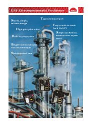
SVC1C2AL1AL2SELMicro-controller XModel: <strong>PXR3</strong>Operation <strong>Manual</strong>ECNO:409a
Table of Contents1 Part Names and Functions .................................................................................................... 52 Operations ............................................................................................................................. 62-1 Parameter list ............................................................................................................ 62-2 Basic operations ....................................................................................................... 112-3 Parameter functions and method of settings ............................................................ 12 First block parameters ............................................................................................... 13Standby setting .......................................................................................................... 13Ramp-soak control..................................................................................................... 14Canceling the alarm latch .......................................................................................... 15Auto-tuning function ................................................................................................... 16Displaying ON-delay alarm or the remaining time of timers ...................................... 17Setting alarm 1 and 2 ................................................................................................ 18Upper limit of alarm 1 and 2 ...................................................................................... 18Lower limit of alarm 1 and 2....................................................................................... 18Key lock ..................................................................................................................... 19 Second block parameters .......................................................................................... 20Proportional band ...................................................................................................... 20Integral time ............................................................................................................... 21Derivative time ........................................................................................................... 22Hysteresis range for ON/OFF control ........................................................................ 23Cooling-side proportional band coefficient ................................................................ 24Cooling-side proportional band shift (Dead band/Overlap band) .............................. 25Output offset value ..................................................................................................... 26Anti-reset windup ....................................................................................................... 26Control algorithm ....................................................................................................... 27PV (Measured value) stable range ............................................................................ 31HYS (Hysteresis) mode at ON/OFF control ............................................................... 32Cycle time of control output 1 .................................................................................... 33Cycle time of control output 2 (cooling-side).............................................................. 34Input signal code........................................................................................................ 35Setting lower limit of the measuring range ................................................................. 36Setting upper limit of the measuring range ................................................................ 36Decimal point position................................................................................................ 38PV offset .................................................................................................................... 39SV offset .................................................................................................................... 40Time constant of input filter........................................................................................ 41Alarm types ................................................................................................................ 42Selecting ramp-soak patterns .................................................................................... 45Ramp-soak status display .......................................................................................... 461st to 8th target SV .................................................................................................... 461st to 8th ramp segment time .................................................................................... 461st to 8th soak segment time ..................................................................................... 46Ramp-soak modes..................................................................................................... 46 Third block parameters .............................................................................................. 49Specifying control system and action, and output direction at input burn-out............ 492
SV (Setting value) lower limiter .................................................................................. 50SV (Setting value) upper limiter ................................................................................. 50The time of ON-delay alarm or timer function ............................................................ 51Hysteresis alarm 1 and 2 ........................................................................................... 53Options of alarm 1 and 2 ........................................................................................... 54Upper and lower limits for control output 1 ................................................................ 56Upper and lower limits for control output 2 ................................................................ 56Output limit types ....................................................................................................... 57Output value display .................................................................................................. 58RCJ (Cold junction compensation) ............................................................................ 59Adjusting the PV (Measured value) display (0%)....................................................... 60Adjusting the PV (Measured value) display (100%)................................................... 60DI operation ............................................................................................................... 61Station No. for communication ................................................................................... 64Parity for communication ........................................................................................... 65Input type for PYP ...................................................................................................... 66Retransmisson output type setting ............................................................................ 67Retransmisson base scale......................................................................................... 68Retransmisson span scale......................................................................................... 68Parameter display mask ............................................................................................ 693 Troubleshooting ...................................................................................................................... 70Index ......................................................................................................................................... 723
PXRdigit Specification Note456789101112131424 × 48 mmThermocouple °CThermocouple °FRTD Pt100Ω 3-wire type °CRTD Pt100Ω 3-wire type °F1 to 5V DC4 to 20mA DCRelay contact outputSSR/SSC driving output4 to 20mA DC outputNoneRelay contact outputSSR/SSC driving output4 to 20mA DC outputNoneAlarm 1 point8 ramps/soaksAlarm 1 point + 8 ramps/soaksAlarm 2 pointAlarm 2 point + 8 ramps/soaks None100 to 240V ACJapanese100 to 240V ACEnglish100 to 240V ACNone24V AC/24V DCJapanese24V AC/24V DCEnglish24V AC/24V DCNoneRS-485 Modbus interfaceRS-485 Z-ASCLL interfaceRetransmission + Digital input 1 pointRetransmissionDigital input 2 pointsRS-485 Modbus interface + Digital input 1 pointRS-485 Z-ASCLL interface + Digital input 1 pointNon-standard parameter settingNote 1Note 1Note 1Note 2Note 2Note 3Note 345678 9 10 11 12 13 143TRNSABACEYACE10145FGNYVCAB0 0 0M 0 0N 0 0Q 0 0R 0 0T 0 0V 0 0W 0 0FModel SpecificationsNote 1 Process alarm (2 points) (the codes “ F and G ” in the 9th digit) cannotbe specified.Note 2 Control output 2 (the codes “ A, C, and E ” in the 7th digit) cannot bespecified.Note 3 Control output 2, communication digital input (2 points), alarm (2points), and 24V power supply (the codes “ A, C and E ” in the 7th digit,“ F and G ” in the 9th digit, and “ A, B, and C ” in the 10th digit) cannotbe specified.The default settings of input signals, measured ranges, and setting valuesare shown below.Thermocouple specified : Thermocouple K, Measured range: 0 to 400°C,Setting value: 0°CResistance bulb specified : Pt, Measured range: 0 to 150°C, Setting value:0°CVoltage, Current specified : Scaling: 0 to 100%, Setting value: 0%In any case other than the description above, specify input signals andmeasured range.The input signals for the thermocouple and the resistance bulb can beswitched with the front panel keys.The default settings of control action is reverse for control output 1 and directfor control output 2.The reverse and direct actions can be switched with keys on the face panel.4
1 Part Names and FunctionsThis chapter explains the part names and functions on the face panel. The face panel has the PV and SV displays, the statusindicating lamp, and the setting keys, etc. Those functions are explained below. Please read and understand them beforeusing the PXR. For details about the setting of parameters, see Chapter 2.SVC1C2AL1AL2SELSELq Lamp for control output 1Lights up while control output 1 stays ON.w Lamp for control output 2Lights up while control output 2 stays ON.e Lamp for alarm output 1 (option)Lights up when alarm output 1 is actuated. Flickers underON-delay operation.r Lamp for alarm output 2 (option)Lights up when alarm output 2 is actuated. Flickers underON-delay operation.t DisplayDisplays the PV (process value) or SV (set value). Whensetting a parameter, its name or its value appears.y SEL keyUsed to switch the PV display to/from the SV displayand select a parameter block and a parameter, and registera set value.u keysUsed to change the SV, call parameters, and change parametervalues.i Auto-tuning/self-tuning lampFlickers under an auto-tuning or self-tuning operation.o SV lampDisplays the PV (process value) in normal condition(while the lamp stays out). Press the SEL key to lightup the SV lamp and display the SV (set value). Note thatthe lamp stays out while parameters and data are displayed.Flickers while the display shows the PV (process value)in standby state.5
2 OperationsThis chapter explains how to set the SV (Setting value) and the parameters for the PXR.2-1 Parameter listParameters for the PXR are classified under three blocks according to the frequency of use. The parameters of the secondand third blocks are used at initialization or when they are of absolute necessity.Some parameters may not be displayed at the time of delivery depending on the type of the instrument.Parameters of the first blockParameterdisplay symbolParameter nameStbyStandbysettingDescriptionSwitches between RUN and Standbyfor control.Setting range andfactory default setting (*)oN: Control standby(Output: OFF, Alarm: OFF)oFF: Control RUN*User’sset valueParametermask DSPdSP1-1Referencepage13ProGRamp-soakcontrolSwitches between Start, Stop, andHold for ramp-soak controloFF: Stop*rUn: StartHLd: HolddSP1-214LACHAlarm latchcancelCancels the alarm latch.0: Keeps the alarm latch.*1: Opens up the alarm latch.dSP1-415ATAuto-tuningUsed for setting the constants for , ,and by auto-tuning.0: OFF (Resets the auto-tuning or doesnot use it.)*1: ON (Performs the auto-tuning in theSV standard type.)2: ON (Performs the auto-tuning inlow PV type (SV value-10%FS).)dSP1-816TM-1TM-2Timer 1 displayTimer 2 displayDisplays the remaining time of timer 1.Displays the remaining time of timer 2.- (Unit: seconds)- (Unit: seconds)dSP1-16dSP1-321717AL1A1-LA1-HAL2A2-LA2-HSet value ofalarm 1Lower limitvalue ofalarm 1Upper limitvalue ofalarm 1Set value ofalarm 2Lower limitvalue ofalarm 2Upper limitvalue ofalarm 2Sets the value at whichalarm 1 is detected.Sets the lower limitvalue at which alarm 1is detected.Sets the upper limitvalue at which alarm 1is detected.Sets the value duringwhich alarm 2 isdetected.Sets the lower limitvalue at which alarm 2is detected.Sets the upper limitvalue at which alarm 2is detected.is displayedwhen alarm type 1is 0 to 15, or 32 to34, and oris displayedwhen alarm type 1is 16 to 31.is displayedwhen alarm type 2 is 0to 15 or 32 to 34, andor isdisplayed when alarmtype 2 is 16 to 31.When the alarm type is absolute value:0 to 100%FS (*:10)When the alarm type is deviation:-100 to 100%FS (*:10)When the alarm type is absolute value:0 to 100%FS (*:10)When the alarm type is deviation:-100 to 100%FS (*:10)dSP1-128dSP2-1dSP2-2dSP2-4dSP2-8dSP2-16*18*18*18*18*18*18LoCKey lockSpecifies whether or not to allow thechange of parameters.0: All settings are changeable both fromthe face panel and via communication.*1: All settings are unchangeable from theface panel, but changeable viacommunication.2: Only the SV is changeable from theface panel, and all settings arechangeable via communication.3: All settings are changeable from theface panel, but unchangeable viacommunication.4: All settings are unchangeable from theface panel or via communication.5: Only the SV is changeable from theface panel, but all settings are unchangeablevia communication.dSP3-119Note: The parameters for which * is marked with the page number in Reference page are related to Remediesof “4” on page 70.6
Parameters of the second blockParameterdisplay symbolParameter nameDescriptionSetting range and factorydefault setting (*)0 to 100%FS (*: 100%FS)User’sset valueParametermask DSPdSP4-1ReferencepageProportional Set to 0.0 to select the ON/OFF 0.0 to 999.9% (*: 5.0)band control (Two-position control).dSP3-220Integral timeDerivative time0 to 3200 seconds (*: 240)0.0 to 999.9 seconds (*: 60.0)dSP3-4dSP3-82122Hysteresis Sets the hysteresis for ON/OFF 0 to 50%FS (*: equivalent of 1.0°C)range fordSP3-16 *ON/OFFcontrol.23controlCooling-side0.0 to 100.0 (*: 1.0)proportionalband coefficientdSP3-3224Cooling-side-50.0 to +50.0 (*: 0.0)proportionaldSP3-64band shift25Output-100 to 100%convergencevalue(*: single 0.0, dual 50.0)dSP3-12826Anti-resetwindupNote: The parameters for which * is marked with the page number inReference page are related to Remedies of “4” on page 70.26*ControlalgorithmPV (Measuredvalue) stablerangeSetting HYS(Hysteresis)modeSelects the control algorithm.Sets the PV stable range for the selftuningoperation.Selects the hysteresis operation atON/OFF control.PID: Runs normal PID control.*FUZY: Runs PID control with fuzzy logic.SELF: Runs PID control with self-running.0 to 100%FS (*: 2%FS)oFF: Starts the two-position control at thevalues of SV+HYS/2 and SV-HYS/2.on: Starts the two-position control at the valuesof SV and SV+HYS, or SV and SV-HYS.dSP4-2dSP4-4dSP4-8273132*Cycle timeof controloutput 1Not shown at 4-20mA DC outputRLY, SSR: 1 to 150 seconds(*: Contact output = 30,SSR/SSC-driven output = 2)dSP4-1633Cycle timeof controloutput 2(cooling-side)RLY, SSR: 1 to 150 seconds(*: Contact output = 30,SSR/SSC-driven output = 2)dSP4-3234Input signalcodeSet this parameter when changingthe types of temperature sensors.1 to 16 (*: specified by customer whileordering) Note 1dSP4-6435Lower limit ofmeasuring range-1999 to 9999 (*: specified by customerwhile ordering) Note 1dSP4-12836Upper limit ofmeasuring range-1999 to 9999 (*: specified by customerwhile ordering) Note 1dSP5-136Setting the decimalpoint position0 to 2 (*: specified by customer whileordering) Note 1dSP5-238°C / °FselectionPV (Measuredvalue) offsetSV (Settingvalue) offsetTime constantof input filterShift the display of the PV.Shift the SV. But the SV displayis not changed.°C / °F-10 to 10%FS (*: 0)-50 to 50%FS (*: 0)0.0 to 900.0 seconds (*: 5.0)dSP5-4dSP5-8dSP5-16dSP5-3236394041**Alarm type 1Alarm type 2Sets the types of alarm operations.Sets the types of alarm operations.0 to 34 (*: 0/5)0 to 34 (*: 0/9)dSP5-64dSP5-1284242Status displayof ramp-soak- (*: OFF)dSP6-246Selectingramp-soakexecute typeSelects ramp-soak patterns.1: Performs 1st to 4th segments.*2: Performs 5th to 8th segments.3: Performs 1st to 8th segments.dSP6-4451st target value/Switching-SVvalueSets the 1st target SV of ramp-soakoperation. / Selected at switching-SV function for DI1Within the SV limit. (*: 0%FS)dSP6-846*First rampsegment timeSets the first ramp segment time.0 to 99h59m (*: 0.00)dSP6-16467
Parameterdisplay symbolParameter nameDescriptionSetting range and factorydefault setting (*)User’sset valueParametermask DSPReferencepage1st soaksegment timeSets the 1st soak segment time.0 to 99h59m (*: 0.00)dSP6-32462nd target SVSets the 2nd target SV of ramp-soakoperation.Within the SV limit. (*: 0%FS)dSP6-64*462nd rampsegment timeSets the 2nd ramp segment time.0 to 99h59m (*: 0.00)dSP6-128462nd soaksegment timeSets the 2nd soak segment time.0 to 99h59m (*: 0.00)dSP7-1463rd target SVSets the 3rd target SV of ramp-soakoperation.Within the SV limit. (*: 0%FS)dSP7-2*463rd rampsegment timeSets the 3rd ramp segment time.0 to 99h59m (*: 0.00)dSP7-4463rd soaksegment timeSets the 3rd soak segment time.0 to 99h59m (*: 0.00)dSP7-8464th target SVSets the 4th target SV of ramp-soakoperation.Within the SV limit. (*: 0%FS)dSP7-16*464th rampsegment timeSets the 4th ramp segment time.0 to 99h59m (*: 0.00)dSP7-32464th soaksegment timeSets the 4th soak segment time.0 to 99h59m (*: 0.00)dSP7-64465th targetSVSets the 5th target SV of ramp-soakoperation.Within the SV limit. (*: 0%FS)dSP7-128*465th rampsegment timeSets the 5th ramp segment time.0 to 99h59m (*: 0.00)dSP8-1465th soaksegment timeSets the 5th soak segment time.0 to 99h59m (*: 0.00)dSP8-2466th target SVSets the 6th target SV of ramp-soakoperation.Within the SV limit. (*: 0%FS)dSP8-4*466th rampsegment timeSets the 6th ramp segment time.0 to 99h59m (*: 0.00)dSP8-8466th soaksegment timeSets the 6th soak segment time.0 to 99h59m (*: 0.00)dSP8-16467th target SVSets the 7th target SV of ramp-soakoperation.Within the SV limit. (*: 0%FS)dSP8-32*467th rampsegment timeSets the 7th ramp segment time.0 to 99h59m (*: 0.00)dSP8-64467th soaksegment timeSets the 7th soak segment time.0 to 99h59m (*: 0.00)dSP8-128468th targetSVSets the 8th target SV of ramp-soakoperation.Within the SV limit. (*: 0%FS)dSP9-1*468th rampsegment timeSets the 8th ramp segment time.0 to 99h59m (*: 0.00)dSP9-2468th soaksegment timeSets the 8th soak segment time.0 to 99h59m (*: 0.00)dSP9-446Ramp-soakmodeSelects the power-on start, repeat,and standby functions for rampsoakoperations.0 to 15 (*: 0)dSP9-846Note 1: When a customer does not specify the settings while ordering, the following settings are selected as factory defaults.Thermocouple input: Thermocouple K Measured range: 0 to 400°CResistance bulb input: Measured range: 0 to 150°CVoltage/Current input: Scaling: 0 to 100%8
Parameters of the third blockNote: The parameters for which * is marked with the page number inReference page are related to Remedies of “4” on page 70.Parameterdisplay symbolParameter nameControl actionSpecifies control action and output atthe input burn-out.SV (Setting value)lower limiterSets the lower limit of the SV.SV (Setting value)upper limiterSets the upper limit of the SV.Delay time 1 Delay time or timer value for alarm 1 relay.Delay time 2 Delay time or timer value for alarm 2 relay.Alarm 1 hysteresisSets the hysteresis range of ON andOFF of alarm 1.Alarm 2 hysteresisSets the hysteresis range of ON andOFF of alarm 2.Alarm 1 optionsDescriptionSets the optional functions of alarms 1 and 2.Setting range and factorydefault setting (*)0 to 19 (*: specified by customerwhile ordering) Note 20 to 100%FS (*: 0%FS)0 to 100%FS (*: 100%FS)0 to 9999 seconds (*: 0)0 to 9999 seconds (*: 0)0 to 50%FS (*: 1)0 to 50%FS (*: 1)000 to 111 (*: 000)User’sset valueParametermask DSPdSP9-16dSP9-32dSP9-64dSP9-128dSP10-1dSP10-16dSP10-32dSP10-128Referencepage4950**505151*53*5354Alarm 2 optionsAlarm latch (1: use, 0: not use)Alarm of error status (1: use, 0: not use)De-energized output (1: use, 0: not use)000 to 111 (*: 000)dSP11-154Lower limit for output 1 Sets the lower limit for output 1.-3.0 to 103.0% (*: -3.0)dSP11-456Upper limit for output 1 Sets the upper limit for output 1.-3.0 to 103.0% (*: 103.0)dSP11-856Lower limit for output 2 Sets the lower limit for output 2.-3.0 to 103.0% (*: -3.0)dSP11-1656Upper limit for output 2 Sets the upper limit for output 2.-3.0 to 103.0% (*: 103.0)dSP11-3256Output limit typesSets the limit types of outputs 1 and2 (breaking the limit, or maintainedwithin the limit).0 to 15 (*: 0)dSP11-6457Output value (MV)displayDisplays the value of output 1.-dSP11-12858Output value (MV)displayDisplays the value of output 2.-dSP12-158RCJ (Cold junctioncompensation)settingSets the cold junction compensationfunction to ON/OFF.ON: Performs the RCJ (Cold junctioncompensation).*OFF: Does not perform the RCJ(Cold junction compensation).dSP12-259PV gradient0.001 to 2.000 (*: 1.000)dSP12-4User-definable zeroadjustmentShifts the zero point of input value.-50 to 50%FS (*: 0)dSP12-8*60User-definable spanadjustmentShifts the span of input value.-50 to 50%FS (*: 0)dSP12-16*60DI1 (Digital input 1)operationSets the DI1 operations.0 to 12 (*: 0=OFF)dSP12-3261DI2 (Digital input 2)operationSets the DI2 operations.0 to 12 (*: 0=OFF)dSP12-6461Station No.Sets the station No. forcommunication.0 to 255 (Setting to does not startthe communications function.) (*: 1)dSP12-12864Parity settingSets the parity for communication.(The baud rate is fixed at 9600bps.0: Odd parity*1: Even parity2: No paritydSP13-165Input type for PYP(Color Touch-Operation Unit)Sets the input type for communicatingwith PYP.0 to 255 (*: 34)dSP13-266Retransmissionoutput typeSelecting retransmission output type.0: PV/ 1: Set point/ 2: Output/3: Error (* : 0)dSP13-467Retransmissionbase scaleSetting retransmission base scale.(Setting range: 0 to 100%) (* : 0%)dSP13-868Retransmissionspan scaleSetting retransmission span scale.(Setting range: 0 to 100%) (* : 100%)dSP13-1668Note 2: The following settings are selected as factory defaults depending on the model you order.Seventh digit = Y model: 0 Seventh digit = A, C, E model: 49
Parameterdisplay symbolParameter nameDescriptionSetting range and factorydefault setting (*)User’sset valueParametermask DSPReferencepagetotototoParameter mask Sets whether or not to display each 0 to 255 (*: specified by customerparameter.while ordering)– 6910
2-2 Basic operationsJust after power-on:The PV (process value) is displayed just after power-on.SVC1C2AL1AL2SELExp.) In case when the PV (process value)is 149.9.How to switch parameters:The figure below shows the basic operations for the <strong>PXR3</strong>.Basic operations for the <strong>PXR3</strong>(SV indication)SVC1C2AL1AL2SELSELDisplay state just after power-on(PV indication)SVC1C2AL1AL2SELParameter settingFlickers when the set value ischanged by pressing theor key.Stop flickering when the SVis registered by pressing theSEL key.Indication switching PV (process value)to / from SV (set value)SEL(apporox.1 second)OFFSV lampSEL(apporox.3 second)SEL(apporox.5 second)Set data indicationSELSELSet data registrationLit, flickersPress the SEL key toswitch PV to / from SV.Parameters ofthe first blockParameters ofthe second blockParameters ofthe third blockPressing and holding thekeys makes the value increaseor decrease fast.If it has not been operated for 30 seconds, the display returns to the PV display.Pressing the SEL key for 2 second after setting parameters, the indicationshifts to the SV indication state.How to set values:key: One press increases the value by 1.Press and hold this key to increase the value.key: One press decreases the value by 1.Press and hold this key to decrease the value.How to register the set data:By pressing the SEL key, the displayed values are registered.Note that the SV (SV0) will be registered in 3 seconds without any operation. (Refer to P.12)When changed the parameters “P-n2”, “ALM1” or “ALM2”, turn the power OFF and ON.11
2-3 Parameter functions and method of settingsMethod of setting the SV (Setting value)[Description]• The SV is a target value for control.• Any SV that is outside of the range set in the parametersof (lower limit) and (upper limit) of thethird block cannot be set. (See page 50.)Related parameters: (page 50)(page 50)[Setting example] Changing the SV from 250.0°C to 348.7°CDisplayPV indicationSV indication1.2.Operating procedurePress the SEL key to display the SV. (SV lamp is lit.)Press the or keys to display .3.will be registered in the SV (front SV) in three seconds. After that, the controller willoperate with the SV being .12
q First block parametersStandby setting (Settings: oFF/on)[Description]• This parameter switches the control between RUN andStandby.• During standby, the control output and the alarm outputstay OFF, like the standby for ramp-soak operation.Retransmission output is kept operated. (However, if thetype of retransmission output is set to the MV, it becomes4mA or lower.)• While the alarm with a hold is selected, the hold functiontakes effect after changing the Standby setting from ONto OFF.• is displayed during the standby for ramp-soakoperations or the controller changes to the standby statein case of the occurrence of errors.• The other operations are the same as those of the rampsoakstandby.• The setting of ON/OFF for standby is saved after poweroff.• When the standby is set to ON during the auto-tuning,self-tuning, and ramp-soak operations, those operationswill stop. (The PID constant will not be renewed.) Eventhrough it is set to OFF later, the auto-tuning, self-tuning,and ramp-soak operations will not be re-started.• During standby, the ON-delay timer is reset. Whenreturning to RUN from the standby state, the timer willstart from the beginning.• The SV lamp flickers only when standby state.[Setting example] Starting the controlDisplayOperating procedurePV indication1.2.Press and hold the SEL key for one second.will be displayed.Press the SEL key once.The current setting ( ) will be displayed.SV indicationPV indication3.4.5.Press the or keys to flicker and to display .Press the SEL key once. The standby state for control is selected. (control output and all the alarmoutputs: OFF)(Repeat the procedure from 2 to 4 to check the set value.)If you want to display the operation status, press and hold the SEL key for two seconds. The valueon the SV display will flash, indicating the standby status.If unoperated state continues, the PV will be displayed.13
Ramp-soak control (Settings: oFF/rUn/hLd) (Option)[Description]• This function automatically changes the SV (Settingvalue) according to the program pattern set in advance asshown in the right line graph. Up to eight pairs of rampsoakoperation can be programmed.• The first ramp starts at the PV (Measured value) that isthe one just before running the program.• The program can also automatically run at power-on(Power-on starting function). Refer to the parameter of(page 46).Related parameters: (page 46)to (page 46)to (page 46)to (page 46)(page 46)(page 45)Up to SV-8SV-3SV-2SV-1SV-4PVFirst rampTM1rFirst soakSecond rampSecond soakThird rampTM1S TM2S TM3STM2r TM3rTM4rTM4S Up to TM8sUp to TM8rRamp: the section in which the SV changes toward the target value.Soak: the section in which the SV is the target value, and remains unchanged.Third soakFourth rampFourth soak[Setting example] Starting the ramp-soak operationDisplayPV indicationSV indicationPV indication1.2.3.4.5.6.Press and hold the SEL key for one second.will be displayed.Press the key to display .Press the SEL key once.The current setting ( ) is displayed.Operating procedurePressing the or keys, the display flickers and is displayed.Press the SEL key once. Then, the program will start according to the ramp-soak pattern that isset in advance. *1(Repeat the procedure from 3 to 5 to check the set value.)If you want to display the operation status, press and hold the SEL key for two seconds.The SV is displayed on the display area.If unoperated state continues, the PV will be displayed.*1) When the program was not set, it is turned to .14
Canceling the alarm latch (Setting range: 0/1) (Option)[Description]• This parameter cancels the alarm latch when it is latching. Related parameters:to (page 54)[Setting example] Opening up the alarm latchDisplayOperating procedurePV indication1.2.3.4.Press and hold the SEL key for one second.will be displayed.Press the key to display .Press the SEL key once.The current setting ( ) is displayed.Pressing the or keys to flicker and to display .SV indication5.6.Press theSEL key once.(Repeat the procedure from 3 to 5 to check the set value.)If you want to display the operation status, press and hold theThe SV is displayed on the display area.SEL key for two seconds.PV indicationIf unoperated state continues, the PV will be displayed.15
Auto-tuning function (Settings: 0/1/2)[Description][Note]If the controller is powered off during auto-tuning, thismakes the auto-tuning ineffective with each parameterof , , and unchanged. To start the auto-tuningoperation, set to “1” or “2” again.• To suspend the auto-tuning, set to “0”. This makesthe auto-tuning cancel with each parameter of , , andunchanged.• Once the parameters of , , and are set automaticallyby the auto-tuning, those parameters are stored in thecontroller even after it is powered off. Therefore, it is notnecessary to execute the auto-tuning again.• By setting to “1” or “2” , the auto-tuning operationstarts, and at the end of the tuning, will be displayedautomatically to .• After the auto-tuning operation, the controller starts tooperate at the automatically set values of , , and .• A decimal point at the right end of the SV display flashesduring auto-tuning.• There are two codes for AT:Setting code [1]: SV standard typePerforms the auto-tuning based on the SV.Setting code [2]: Low PV typePerforms the auto-tuning based on theSV-10%FS.[Note]Since ON/OFF control is performed during auto-tuning,overshoot against the SV may occur. To reducethe overshoot, execute the auto-tuning operation withthe setting code [2] (Low PV) selected.• The auto-tuning can be executed both just after power-onand in a control or stable status.Related parameters:(page 20)(page 21)(page 22)(page 26)(page 24)[Setting example] Setting the auto-tuning operation to 1DisplayPV indicationPV indicationSV indicationPV indication1.2.3.4.5.6.7.Press and hold the SEL key for one second.will be displayed.Press the key to display .Press the SEL key once.The current setting ( ) is displayed.Operating procedurePress the or keys to flicker the display and to display .Press the SEL key once. is displayed and the auto-tuning will start. During auto-tuning,a decimal point at the first digit from the right end of the display flickers.(Repeat the procedure from 3 to 5 to check the set value.)When the auto-tuning finishes properly, a decimal point stops flashing, and the set values of , ,and parameters change. When the auto-tuning finishes abnormally, a decimal point stops flashing,but the set values of , , and parameters remain unchanged.If you want to display the operation status, press and hold the SEL key for two seconds.The SV is displayed on the display area.If unoperated state continues, the PV will be displayed.16
, Displaying ON-delay alarm or the remaining time of timers (unit: seconds) (Option)[Description]• These parameters display the remaining time of Timers 1and 2.• The remaining time of the ON/OFF-delay timer is counteddown. When the counter shows , the alarm relay isclosed.• During count-down, if the PV changes to the value of thetemperature at which the alarm is set to OFF, or if “DI”for the timer is set to OFF, the counter is reset, and thealarm relay is opened.• display parameterSELSEL[Setting example] Displaying ON-delay alarm or the remaining time of timersDisplayPV indication1.2.3.Press and hold the SEL key for one second.will be displayed.Operating procedurePress the key to display . By pressing the SEL key,the remaining time (10 seconds) of the timer 1 will be displayed. Pressing theit returns to display.SEL key again,Press the key to display . By pressing the SEL key, the remaining time (8 seconds)of the timer 2 will be displayed. Pressing the SEL key again, it returns to display.SV indication4.If you want to display the operation status, press and hold theThe SV is displayed on the display area.SEL key for two seconds.PV indicationIf unoperated state continues, the PV will be displayed.17
Setting alarm 1 and 2Upper limit of alarm 1and 2Lower limit of alarm 1and 2(Setting range:Absolute value alarm: 0 to 100%FSDeviation value alarm: -100 to 100%FS )}(Option)[Description]• These parameters are used to for settings of alarm 1and 2.• When the alarm type ( or ) is set to 0 to 15,alarms 1 and 2 ( and ) can be set.• When the alarm type ( or ) is set to any valueother than 0 to 15, the upper and lower limits of alarm 1and 2 ( , , , ) can be set.[Note]Setting codes (12 to 15) cannot be selected in alarmtype 1 ( ).Related parameters: , (page 42), (page 53), (page 51), (page 54)[Setting example] Setting the operation value of alarm 2 to -10°CDisplayPV indicationSV indicationPV indication1.2.3.4.5.6.Press and hold the SEL key for one second.will be displayed.Press the key to display .Press the SEL key once.The current setting ( ) will be displayed.Operating procedurePress the or keys to flicker and to display .Press the SEL key once. will be displayed and the operation value -10°C will be registeredfor . After that, the controller will operate with the operation value of = -10°C.(Repeat the procedure from 3 to 5 to check the set value.)If you want to display the operation status, press and hold the SEL key for two seconds.The SV will be displayed on the display area.If unoperated state continues, the PV will be displayed.18
Key lock (Setting range: 0−5)[Description]• This parameter makes the set values of parametersunchangeable. However, the parameter name and the setvalues can be displayed.• To reset the key lock, change to .• Even when the key lock is set, control and alarm functionscan operate properly.• There are six levels of the key lock:: Unlocked (reset): All settings are unchangeable from the controller, butchangeable via communication.: Only the SV is changeable from the controller, and allsettings are changeable via communication.: All settings are changeable from the controller, butunchangeable via communication.: All settings are unchangeable from the controller orvia communication.: Only the SV is changeable from the controller, but allsettings are unchangeable via communication.[Setting example] Setting the key lock to “2”DisplayPV indicationSV indicationPV indication1.2.3.4.5.6.Press and hold the SEL key for one second.will be displayed.Press the key to display .Press the SEL key once.The current setting ( ) will be displayed.Operating procedurePress the or keys to flicker and to display .Press the SEL key once. will be displayed and "2" will be registered for . After that,any setting other than the SV cannot be changed from the front panel.(Repeat the procedure from 3 to 5 to check the set value.)If you want to display the operation status, press and hold the SEL key for two seconds.The SV will be displayed on the display area.If unoperated state continues, the PV will be displayed.19
w Second block parametersProportional band (Setting range: 0.0 to 999.9% of the measured range)[Description]• To select the ON/OFF control (two-position control), setto 0.0. It is not necessary to set and .• can be automatically set by the auto-tuning operation.• When is too small, control will be unstable, and whenis too large, the response will be delayed.• Set the hysteresis of the ON/OFF control (two-positioncontrol) in the parameter .• If auto-tuning is run after the ON/OFF control is selected,the ON/OFF control changes to the PID control. To keepthe ON/OFF control selected, do not execute the autotuning.Related parameters: (page 23)(page 32)[Setting example] Changing the proportional band from 5.0% to 15.0%DisplayPV indicationSV indicationPV indication1.2.3.4.5.Press and hold the SEL key for three seconds.will be displayed.Press the SEL key once.The current setting ( ) will be displayed.Operating procedurePress the or keys to flicker and to display .Press the SEL key once. will be displayed and the 15.0% will be registered for . After that,the controller will operate with being 15.0%.(Repeat the procedure from 2 to 4 to check the set value.)If you want to display the operation status, press and hold the SEL key for two seconds.The SV will be displayed on the display area.If unoperated state continues, the PV will be displayed.20
Integral time (Setting range: 0 to 3200 seconds)[Description]• can be set automatically by the auto-tuning operation.• can also be set manually.• When is set to 0, the integral operation does not start.• When is set to 0.0, this makes the setting of ineffective.[Setting example] Changing the integral time from 240 seconds to 600 secondsDisplayOperating procedurePV indication1.2.3.4.Press and hold the SEL key for three seconds.will be displayed.Press the key to display .Press the SEL key once.The current setting ( ) will be displayed.Press the or keys to flicker and to display .SV indicationPV indication5.6.Press the SEL key once. will stop flashing and will be registered for . After that, thecontroller will operate with being seconds.(Repeat the procedure from 3 to 5 to check the set value.)If you want to display the operation status, press and hold the SEL key for two seconds.The SV will be displayed on the display area.If unoperated state continues, the PV will be displayed.21
Derivative time (Setting range: 0.0 to 999.9 seconds)[Description]• can be set automatically by the auto-tuning operation.• can also be set manually.• When is set to 0, the differential operation does not start.• When is set to 0.0, this makes the setting of ineffective.[Setting example] Changing the differential time from 60.0 seconds to 50.0 secondsDisplayOperating procedurePV indication1.2.3.4.Press and hold the SEL key for three seconds.will be displayed.Press the key to display .Press the SEL key once.The current setting ( ) will be displayed.Press the or keys to flicker and to display .SV indicationPV indication5.6.Press the SEL key once. will be displayed and 50.0 seconds will be registered for . After that,the controller will operate with being 50.0 seconds.(Repeat the procedure from 3 to 5 to check the set value.)If you want to display the operation status, press and hold the SEL key for two seconds.The SV will be displayed on the display area.If unoperated state continues, the PV will be displayed.22
Hysteresis range for ON/OFF control (Setting range: 0 to 50%FS)[Description]• To select the ON/OFF control (two-position control), setto 0.0. It is not necessary to set and .• When the hysteresis range (Range of ON/OFF control) istoo small, the output may switch the ON/OFF frequently.(This may affect the life of the device to be controlled,especially when contact output is selected.)• The unit of the set value of this parameter is ºC or ºF(engineering unit). The setting range varies according tothe measured range of input.[Ex] Input Thermocouple K : At measured range of 0to 400 ºC, the settingrange is 0 to 200 ºC.Resistance bulb : At measured range of 0to 150 ºC, the settingrange is 0 to 75 ºC.Related parameters: (page 20)(page 32)[Setting example] Changing the hysteresis range from 1˚C to 35˚CDisplayPV indicationSV indicationPV indication1.2.3.4.5.6.Press and hold the SEL key for three seconds.will be displayed.Press the key to display .Press the SEL key once.The current setting ( ) will be displayed.Operating procedurePress the or keys to flicker and to display .Press the SEL key once. will be displayed and 35˚C will be registered for . After that,the controller will operate with the being 35˚C.(Repeat the procedure from 3 to 5 to check the set value.)If you want to display the operation status, press and hold the SEL key for two seconds.The SV will be displayed on the display area.If unoperated state continues, the PV will be displayed.23
Cooling-side proportional band coefficient (Option: Available for DUAL output only) (Setting range: 0.0 to 100.0)[Description]• This parameter is used for setting the cooling-side proportionalband. (See the figure below.)OutputHeating sideCooling sideCoefficient: 0.5Coefficient: 1.0Coefficient: 2.0• When is set to 0.0 and is set to 0.0 in the dualoutput type, the cooling output is as shown in the figurebelow. The hysteresis is fixed at 0.5%FS.Heating output (Output 1)Cooling output (Output 2)ON 0.5% 0.5% ONHeating-sideproportionalband50Cooling-sideproportionalbandMVOFFHYSSVDBOFFPVProportional band (P)• Before setting the cooling-side proportional band, set theheating-side proportional band to an optimum value. Toselect the two-position control for the cooling side, setto 0.0.Related parameters: (page 23)(page 20)Cooling-side Proportional band (P)=proportional band 2× CoefficientEx) When making the proportional band of 10% of thefull scale with the proportional band (P) being 50%:50%10% = × Coefficient2Consequently, the coefficient is 0.4.[Setting example] Changing the cooling-side proportional band coefficient from 1.0 to 2.5DisplayPV indicationSV indicationPV indication1.2.3.4.5.6.Press and hold the SEL key for three seconds.will be displayed.Press the key to display .Press the SEL key once.The current setting ( ) will be displayed.Operating procedurePress the or keys to flicker and to display .Press the SEL key once. will be displayed and 2.5 will be registered for . After that,the controller will operate with the being 2.5.(Repeat the procedure from 3 to 5 to check the set value.)If you want to display the operation status, press and hold the SEL key for two seconds.The SV will be displayed on the display area.If unoperated state continues, the PV will be displayed.24
Cooling-side proportional band shift (Dead band/Overlap band)(Option: Available for DUAL output only) (Setting range: -50.0 to +50.0)[Description]• This parameter is used for shifting the cooling-side proportionalband from the set value. (See the figure below.) and when it is a negative value, the "Overlap band".• When is a positive value, it is called the "Dead band",• Since the unit of is same one used for MV [%], if youOutputwant to set in the unit of deviation [%], must beHeating sideCooling sideconverted using the equation below.MVOverlapbandDeadbandMV100DB [%] = Deviation × [%]PEx) When making a dead band with a deviation of1.0 [%] from the SV while the proportionalband (P) is 5.0%:100DB [%] = 1.0 × = 20 [%]5.0MV=50%Consequently, set the parameter to 20 [%].• Related parameter: (page 20)[Setting example] Shifting the cooling-side proportional band by 2.0DisplayPV indicationSV indicationPV indication1.2.3.4.5.6.Press and hold the SEL key for three seconds.will be displayed.Press the key to display .Press the SEL key once.The current setting ( ) will be displayed.Operating procedurePress the or keys to flicker and to display .Press the SEL key once. will be displayed and 2.0 will be registered for . After that, thecontroller will operate with being 2.0 %.(Repeat the procedure from 3 to 5 to check the set value.)If you want to display the operation status, press and hold the SEL key for two seconds.The SV will be displayed on the display area.If unoperated state continues, the PV will be displayed.25
Output offset value (Setting range: -100.0 to 100.0 %)Anti-reset windup (Setting range: 0 to 100%FS)[Description]• The anti-reset windup ( ) is automatically set to anoptimum value by the auto-tuning operation.By setting , the amount of overshoot can be adjusted.[Note]By making use of the fuzzy control system equipped withPXR, the amount of overshoot can be minimized withoutsetting and .SVPVAR valueAR value}}In this range, the integraloperation is not performed.In this range, the integraloperation is performed.}In this range, the integraloperation is not performed.[Setting example] Changing the anti-reset windup from 60˚C to 80˚C.DisplayPV indicationSV indicationPV indication1.2.3.4.5.6.Press and hold the SEL key for three seconds.will be displayed.Press the key to display .Press the SEL key once.The current setting ( ) will be displayed.Operating procedurePress the or keys to flicker and to display .Press the SEL key once. will be displaed and 80˚C will be registered for . After that, thecontroller will operate with the being 80˚C.(Repeat the procedure from 3 to 5 to check the set value.)If you want to display the operation status, press and hold the SEL key for two seconds.The SV will be displayed on the display area.If unoperated state continues, the PV will be displayed.26
Control algorithm (Settings: PID/FUZY/SELF)[Description]• This parameter is used for selecting PID control, FUZZY-PID control, or PID control with self-tuning.• To select the PID control or FUZZY-PID control, it isnecessary to set the parameters of , , , andmanually or by the auto-tuning in advance.• For the ON/OFF control (Two-position control), selectthe PID control and then set to 0.0. For detailed information,refer to (page 20).• Refer to the next page for the PID control with self-tuning.[Setting example] Changing the control system from PID to FUZZYDisplayPV indicationSV indicationPV indication1.2.3.4.5.6.Press and hold the SEL key for three seconds.will be displayed.Press the key to display .Press the SEL key once.The current setting ( ) will be displayed.Operating procedurePress the or keys to flicker and to display .Press the SEL key once. will be displayed and FUZZY will be registered fo .After that, the controller will operate with the FUZZY control system activated.(Repeat the procedure from 3 to 5 to check the set value.)If you want to display the operation status, press and hold the SEL key for two seconds.The SV will be displayed on the display area.If unoperated state continues, the PV will be displayed.27
[Self-tuning]1 Function:With the self-tuning function, PID parameters are automatically re-optimised depending on the actual condition of deviceto be controlled and the setting temperature (SV).2 How to execute:Follow the procedure shown below to set and execute the self-tuning. The self-tuning starts to run at the appropriateconditions. (See page 27)q Power on the PXR.w Set the SV.e Select in theparameter of .* 1r Power off the PXR.If the device that is to becontrolled has poweredON at this point:Wait until the temperatureof the device that is to becontrolled falls andstabilizes.To re-start the self-tuning:Select in theparameter of .t Power on the deviceto be controlled.y Power on the PXR.The device to becontrolled and the PXRshould be powered ONat the same time or inorder of the left flowchart.(Tuning / Control) * 2*1: How to set the parameter of :SELSEL*2: Display during self-tuning is shown below:This lamp flickers28
3 Conditions under which the self-tuning runs:q At power-on:The self-tuning runs when all of the following conditions are met.• The SV that appears at power-on is not the same one when the , , , and were set previously. (i.e. ,, , and set by the self-tuning, auto-tuning, manual setting, and writing by communications tools atprevious time)• The (SV-PV) at power-on is larger than (the value of × input range) or (the set value of ).w When the SV is changed:The self-tuning runs when all the conditions below are met.• The changed SV is larger than the SV that was set when the , , , and were selected previously.• The changed amount of the SV is larger than 0.• The changed amount of the SV is larger than (the set value of × input range) or (the set value of ).e When output becomes unstable:The self-tuning runs when control becomes unstable and the hunting of the operating output (MV) occurs. (The selftuningruns only once as long as the SV is not changed.)r When the control standby mode is cancelled:The self-tuning runs by the same reason as "q At power-on" are met.* Only when the PXR is set to standby mode at power-on.4 Conditions under which the self-tuning does not run:q During control standby modew During two-position control (Parameter of = 0)e During auto-tuning operationr During ramp-soak operationt Error display ( or is displayed.)y During dual output (The set value of the parameter of is larger than 4.)u When setting the parameters of , , , and manually (including the setting written by communicationstools)5 Conditions under which the self-tuning is suspended:q At the condition described in 4 shown abovew When the SV is changed during self-tuning operatione When the self-tuning operation can not be completed within approx. 9 hours6 Cautionq Once the PID constant is set, the self-tuning does not operate at next power-on as long as the SV is notchanged.w For an accurate tuning, be sure to power on the device to be controlled before or at the same time as thePXR is powered on. If the PXR has to be powered on first for reasons of the system configuration, performthe auto-tuning with the PID or FUZZY control.e If the device to be controlled is powered on under temperature change (especially when it rises), accuratetunings can not be performed. Be sure to power on the PYX when the temperature of device to be controlledis stabilized.r The self-tuning does not run for cooling system control under Direct Action output (Parameter = 2 or 3).t In case the control is not stable after performing the self-tuning, change the algorithm to the PID or FUZZYcontrol and perform the auto-tuning.29
7 Reference [About the self-tuning method]The PID constant is calculated in one of the following two methods.The method is selected automatically depending on the characteristics of the device to be controlled.• Step response method• Limit cycle methodThe following figures show the operations at power-on and changing the SV, and under unstable control.q Operations at power-onStep response methodLimit cycle methodSVPVSVPVDuring tuningTimeDuring tuningTimew Operations at changing the SVStep response methodLimit cycle methodSVPVChanging the SVSVPVChanging the SVDuring tuningTimeDuring tuningTimee Operation under unstable controlLimit cycle methodPVUnstable control During tuningSVTime100%MV30
PV (Measured value) stable range (Setting range: 0 to 100%FS)[Description]• Self-tuning logic recognizes that control is stable if PV isstaying within the SV ± .• It is not necessary to set this parameter under normal conditions.[Setting example] Changing the PV stable range from 2 to 3DisplayPV indicationSV indicationPV indication1.2.3.4.5.6.Press and hold the SEL key for three seconds.will be displayed.Press the key to display .Press the SEL key once.The current setting ( ) will be displayed.Operating procedurePress the or keys to flicker and to display .Press the SEL key once. will be displayed and 3 will be registered for . After that,the controller will operate with the PV stable range being 3.(Repeat the procedure from 3 to 5 to check the set value.)If you want to display the operation status, press and hold the SEL key for two seconds.The SV will be displayed on the display area.If unoperated state continues, the PV will be displayed.31
HYS (Hysteresis) mode at ON/OFF control (Settings: oFF/on)[Description]• This parameter is used for selecting the hysteresis operationmode at ON/OFF control.onoF : OFFonoF : ON: Starts the ON/OFF control at the values ofHYS HYSSV+ and SV- .22: Starts the ON/OFF control at the values ofSV and SV+HYS, or SV and SV-HYS.• Related parameters: (page 20)(page 23)(page 49)Reverse actionDirect actionHYSSVHYSSVHYSSVHYSSV[Setting example] Setting the hysteresis mode to ONDisplayOperating procedurePV indication1.2.3.4.Press and hold the SEL key for three seconds.will be displayed.Press the key to display .Press the SEL key once.The current setting ( ) will be displayed.Press the key to flicker and to display .SV indicationPV indication5.6.Press the SEL key once. will be displayed and the hysteresis action ON will be registeredfor . After that, the controller will operate with the hysteresis being as shown in the figureof ON above.(Repeat the procedure from 3 to 5 to check the set value.)If you want to display the operation status, press and hold theThe SV will be displayed on the display area.If unoperated state continues, the PV will be displayed.SEL key for two seconds.32
Cycle time of control output 1 (Setting range: 1 to 150 seconds)[Description]• This parameter is applicable for to the contact output andSSR-driving output.• While input is within the proportional band, outputchanges between ON and OFF in cycles. These cyclesare called cycle time.Output: ONCycletimeCycletime• Do not set this parameter to "0".For contact output:The higher the frequency of output is, the more precisethe control becomes. However a high frequency of outputmay shorten the life of the contacts and the device tobe controlled. Be sure to adjust the proportional cyclesconsidering controllability and the life of the device andthe contacts.Typical: 30 secondsFor SSR-driving output:Use in short cycles if there is no problem with the deviceto be controlled.Typical: 1 to 2 seconds[Setting example] Setting the cycle time from 30 seconds to 20 secondsDisplayPV indicationSV indicationPV indication1.2.3.4.5.6.Press and hold the SEL key for three seconds.will be displayed.Press the key to display .Press the SEL key once.The current setting ( ) will be displayed.Operating procedurePress the or key to flicker and to display .Press the SEL key once. will be displayed and 20 seconds will be registered for .After that, the controller will operate with the cycle time being 20 seconds.(Repeat the procedure from 3 to 5 to check the set value.)If you want to display the operation status, press and hold the SEL key for two seconds.The SV will be displayed on the display area.If unoperated state continues, the PV will be displayed.33
Cycle time of control output 2 (Cooling-side)(Setting range: 1 to 150 seconds) (Option: Available for DUAL output only)[Description]• By this parameter is set, the cycle time of control output 2.• While input is within the proportional band, outputchanges between ON and OFF in cycles. These cyclesare called cycle time.Output: ONCycletimeCycletimeFor contact output:The higher the frequency of output is, the more precisethe control becomes. However a high frequency of outputmay shorten the life of the contacts and the device tobe controlled. Be sure to adjust the proportional cyclesconsidering controllability and the life of the device andthe contacts.Typical: 30 secondsFor SSR-drive output:Set it to short time if it does not cause any problem on the• Do not set this parameter to "0".operation end.Typical: 1 to 2 seconds[Setting example] Setting the cooling-side cycle time from 30 seconds to 20 secondsDisplayPV indicationSV indicationPV indication1.2.3.4.5.6.Press and hold the SEL key for three seconds.will be displayed.Press the key to display .Press the SEL key once.The current setting ( ) will be displayed.Operating procedurePress the or key to flicker and to display .Press the SEL key once. will be displayed and 20 seconds will be registered for .After that, the controller will operate with the cooling-side cycle time being 20 seconds.(Repeat the procedure from 3 to 5 to check the set value.)If you want to display the operation status, press and hold the SEL key for two seconds.The SV will be displayed on the display area.If unoperated state continues, the PV will be displayed.34
Input signal code (Setting range: 0 to 16)[Description]• This parameter is used for selecting input signals. Inputsignal varies depending on the sensors (2 types below).Set a code that corresponds to the sensor you use.Type I : Thermocouples (9 kinds of signals)Resistance bulbs (1 kind of signal)Type II : Voltage, current• Input signals can be selected within the same type. It isimpossible to select input signals of a different type.• For type II, when changing from the voltage input to thecurrent input, connect the supplied resistance of 250 Ωbetween terminals w and e .When changing from the current input to the voltage input,remove the resistance of 250 Ω connected to the inputterminals.[Note]After changing the codes, power off the PXR, and thenpower it on again.• Input signals and codesq Input signals code tableTypeInput signalResistance bulb (RTD)• Pt 100Thermocouple• J• K• RI • B• S• T• E• N• PL-IIII1 to 5 V, 4 to 20mA DCCode12345678121316[Setting example] Changing from thermocouple K to thermocouple T in Type IDisplayPV indicationSV indicationPV indication1.2.3.4.5.6.Press and hold the SEL key for three seconds.will be displayed.Press the key to display .Press the SEL key once.The current setting ( ) will be displayed.Operating procedurePress the or key to flicker and to display .Press the SEL key once. will be displayed and the thermocouple T will be registered for. After that, the controller will operate with the kind of input signals being thermocouple T.(Repeat the procedure from 3 to 5 to check the set value.)If you want to display the operation status, press and hold the SEL key for two seconds.The SV will be displayed on the display area.If unoperated state continues, the PV will be displayed.35
Setting lower limit of the measuring range (Setting range: -1999 to 9999)Setting upper limit of the measuring range (Setting range: -1999 to 9999)Selection ˚C / ˚F (Setting: ˚C or ˚F )[Description]• These parameters are used for setting the lower and upperlimits of the measured range.• A decimal point position can be set in the parameter of.• For the current and voltage inputs, = , , and forother inputs, = are valid.• See the right table for input range.w Input range table (Standard range)Input typeResistancebulb JIS(IEC)ThermocoupleDirect-currentvoltagePt100ΩJJKKKRBSTTEENPL-II1 to 5 V DC0000-50-100-150-15000000000-150-1500-15000Range(°C)totototototototototototototototototototototo150300500600100200600850400800400800120016001800160020040080080013001300With / withouta decimal point(°C)*OOOOOOOXOOOOXXXXOOOOXX32323232-58-148-238-2383232323232323232-238-23832-2383232-1999 to 9999(Scaling is possible)Range(°F)totototototototototototototototototototototo3025729321112212392111215627521472752147221922912327229123927521472147223722372With / withouta decimal point(°F)*OOOXOOXXOXOXXXXXXXXXXXSettable upto 2 digits* O: withX: without* For 4 to 20 mA DC input, connect a resistance of 250Ω betweenterminals and to change the input to the 1 to 5 V DC input.[Note]The input accuracy is ±0.5%FS±1 digit except the cases shownbelow.Thermocouple R at 0 to 400 °C : ±1%FS ± 1 digit ±1˚CThermocouple B at 0 to 500 °C : ±5%FS ± 1 digit ±1˚COther kinds of thermocouples : ±0.5% FS ± 1 digit ±1˚C36
[Setting example] Changing the measuring range from 0°C to 150°C to -100°C to 200°C (Pt100)DisplayPV indication1.2.3.4.Press and hold the SEL key for three seconds.will be displayed.Press the key to display .Press the SEL key once.The current setting ( ) will be displayed.Operating procedurePress the or key to flicker and to display .5.6.7.Press the SEL key once. will be displayed and -100 will be registered for .(Repeat the procedure from 3 to 5 to check the .)Press the key to display .Press the SEL key once.The current setting ( ) will be displayed.8. Press the or key to flicker and to display .SV indicationPV indication9.10.Press the SEL key once. will be displayed and will be registered for .After that, the controller will operate with the measured range being -100˚C to 200˚C.(Repeat the procedure from 7 to 9 to check the .)If you want to display the operation status, press and hold the SEL key for two seconds.The SV will be displayed on the display area.If unoperated state continues, the PV will be displayed.37
Decimal point position (Settings: 0 / 1 / 2)[Description]• This parameter is used for selecting the number of decimalpoint positions for the process value (PV) .Related parameters: (page 36)(page 36)"0" (No digit after decimal point)"1" (1 digit after decimal point)"2" (2 digits after decimal point. This is valid only for the voltage and current inputs)[Setting example] Changing the decimal point position setting from 0 to 1DisplayOperating procedurePV indication1.2.3.4.Press and hold the SEL key for three seconds.will be displayed.Press the key to display .Press the SEL key once.The current setting ( ) will be displayed.Press the keys to flicker and to display .SV indicationPV indication5.6.Press the SEL key once. will be displayed and will be registered for . After that,the controller will operate with one decimal point position displayed.(Repeat the procedure from 3 to 5 to check the set value.)If you want to display the operation status, press and hold the SEL key for two seconds.The SV will be displayed on the display area.If unoperated state continues, the PV will be displayed.38
PV offset (Setting range: -10 to 10%FS)[Description]• With this function, predetermined value is added to the inputreading. This parameter is used for adjusting <strong>PXR3</strong>’sindication so that it becomes same as the one of the recorder.• The <strong>PXR3</strong> operates at the displayed PV (the value towhich the PV offset value is added).[Setting example] Adding the PV offset value of 5°C to the input value of 1200 °CDisplayPV indicationSV indicationPV indication1.2.3.4.5.6.Press and hold the SEL key for three seconds.will be displayed.Press the key to display .Press the SEL key once.The current setting ( ) will be displayed.Operating procedurePress the or keys to flicker and to display .Press the SEL key once. will be displayed and will be registered for , and then offset5˚C will be added to the input value. After that, the controller will operate so that the value towhich the offset value of 5˚C is added can be brought close to the set value.(Repeat the procedure from 3 to 5 to check the set value.)If you want to display the operation status, press and hold the SEL key for two seconds.The SV will be displayed on the display area.If unoperated state continues, the PV will be displayed.39
SV offset (Setting range: -50 to 50%FS)[Description]• With this function, predetermined value is added to the originalSV. This parameter is used to eliminate the offset thatoccurs in performing P control.• The <strong>PXR3</strong> operates based on the SV to which the SV offsetvalue is added.• Alarm judgment is made by the displayed SV to whichthe SV offset value is not added.• When the retransmission output type is set to the SV, thedisplayed SV, to which the SV offset value is not added,is output.[Setting example] Adding the SV offset value of 9°C to the currently set valueDisplayPV indicationSV indicationPV indication1.2.3.4.5.6.Press and hold the SEL key for three seconds.will be displayed.Press the key to display .Press the SEL key once.The current setting ( ) will be displayed.Operating procedurePress the or keys to flicker and to display .Press the SEL key once. will be displayed and will be registered for .(The displayed SV remains unchanged.) After that, the controller will operate at the SV value towhich the SV offset value of 9˚C is added.(Repeat the procedure from 3 to 5 to check the set value.)If you want to display the operation status, press and hold the SEL key for two seconds.The SV will be displayed on the display area.If unoperated state continues, the PV will be displayed.40
Time constant of input filter (Setting range: 0.0 to 900.0 seconds)[Description]• This parameter is used for reducing the fluctuation of inputsignal (filter function).For example, when the input filter constant is set to 5seconds, the PV changes as shown in right figure whileinput changes from 0 to 100% suddenly. It takes 5 secondsfor the PV to change from 0 to 63.2%.X°C100InputfilterYPIDInputControl output[Note]The factory default setting is 5.0 (5 seconds). Do notchange this parameter as long as changing is not of absolutenecessity.63(%)5 secondsPV displayt[Setting example] Changing the filter constant from 5.0 (5 seconds) to 10.0 (10 seconds)DisplayPV indicationSV indicationPV indication1.2.3.4.5.6.Press and hold the SEL key for three seconds.will be displayed.Press the key to display .Press the SEL key once.The current setting ( ) will be displayed.Operating procedurePress the or keys to flicker and to display .Press the SEL key once. will be displayed and will be registered for . After that,the controller will operate with the filter constant being 10.0.(Repeat the procedure from 3 to 5 to check the set value.)If you want to display the operation status, press and hold the SEL key for two seconds.The SV will be displayed on the display area.If unoperated state continues, the PV will be displayed.41
, Alarm types (Setting range: 0 to 34) (Option)[Description]• These parameters are used for selecting the operation typesof Alarms 1 and 2.• Alarm1 is activated in the same way as Alarm2 except for codes12 to 15. (Codes 12 to 15 cannot be selected for Alarm1 .)• When any code of 12 to 15 is selected for Alarm 2, Alarm 2is activated and Alarm 1 is cancelled. "Alarm hysteresis","Delay time", and "Alarm latch" can be selected in Alarm 2settings.• The display of the parameter in which the alarm value is setvaries depending on the alarm operation types.[Note] Alarm set value and alarm operationsAlarm set value (AL)Plus setting Minus setting[Note]• Since the alarm set value may change after changing thealarm operation types, be sure to set the alarm set valueagain.• After changing the alarm operation types, power the PXRoff, and then on.• Setting code 0 indicates "No alarm".Related parameters: , (page 53), (page 54), (page 18), (page 51)AbsolutevalueUpperlimitLowerlimitAL0AL0DisabledDisabledDeviationvalueUpperlimitLowerlimitALSVALSVALSVALSV[Setting example] Changing the alarm type of Alarm 2 from upper-limit deviation to the upper-limit deviation with holdDisplayPV indicationSV indicationPV indication1.2.3.4.5.6.Press and hold the SEL key for three seconds.will be displayed.Press the key to display .Press the SEL key once.The current setting ( ) will be desplayed.Operating procedurePress the keys to flicker and to display .Press the SEL key once. will be displayed and will be registered for . After that,the controller will operate with Alarm 2 of upper limit deviation with hold.(Repeat the procedure from 3 to 5 to check the set value.)If you want to display the operation status, press and hold the SEL key for two seconds.The SV will be displayed on the display area.If unoperated state continues, the PV will be displayed.42
[Alarm type list]The table below shows the meaning of symbols in the following operation figures.Alarm type0~1516~31Display symbolAL1A1-LA1-HAlarm 1 Alarm 2Screen nameSet value of Alarm 1Lower-limit of set value of Alarm 1Upper-limit of set value of Alarm 1Display symbolAL2A2-LA2-HScreen nameSet value of Alarm 2Lower-limit of set value of Alarm 2Upper-limit of set value of Alarm 2• Alarm 1 is activated in the same way as Alarm 2 except codes 12 to 15. (Codes 12 to 15 cannot be selected for Alarm 1.If any of them is set, it is recognized as code 0, which indicates "No alarm". )• When any code of 12 to 15 is selected for Alarm 2, Alarm 2 is activated and Alarm 1 is not raised. "Alarm hysteresis","Delay time", and "Alarm latch" can be selected in Alarm 2 settings.• The display of the parameter in which the alarm value is set varies depending on the alarm operation types.• Since the alarm set value may change after changing the alarm operation types, confirm the alarm set value. (Note thatthis is not abnormal.)• Alarm codes for standard typesALM1ALM2Alarm typeOperation figureALM1ALM2Alarm typeOperation figureAbsolutevaluealarmDeviationvaluealarm01234560123456No alarmUpper-limitabsolute valueLower-limitabsolute valueUpper-limitabsolute value(with hold)Lower-limitabsolute value(with hold)Upper-limitdeviationLower-limitdeviationALnALnALnALnALnSVALnSVPVPVPVPVPVPVPVRangealarm11----1112131415Range upper andlower limits deviation(ALM1/2 independentoperation)Range upperand lower limitsabsolute valueRange upper andlower limitsdeviationRange upper limitabsolute value andlower limit deviationRange upper limitdeviation and lowerlimit absolute valueALn ALnSVAL2AL1AL2 AL1SVAL2SV AL1AL1AL2 SVPVPVPVPVPV7878Upper and lowerlimits deviationUpper-limitdeviation (with hold)ALnSVALnSVALnPVPV• Timer codesALM1ALM2Alarm typeOperation figure910910Lower-limitdeviation (with hold)Upper and lowerlimits deviation(with hold)ALnSVALn ALnSVPVPVTimer32333233ON-delaytimerOFF-delaytimerDiALMDiALMdLYndLYn3434ON/OFFdelaytimerDiALMdLYndLYn43
• Alarm codes with dual set valuesALM1ALM2Alarm typeOperation figureALM1ALM2Alarm typeOperation figureUpperandlowerlimitsalarm16171819202122231617181920212223Upper andlower limitsabsolute valueUpper and lowerlimits deviationUpper limitabsolute value andlower limit deviationUpper limitdeviation and lowerlimit absolute valueUpper and lowerlimits absolutevalue (with hold)Upper and lowerlimit deviation(with hold)Upper limit absolutevalue and lower limitdeviation (with hold)Upper limit deviationand lower limit absolutevalue (with hold)A1-LA2-LA1-LA2-LA1-LA2-LA1-LA2-LA1-LA2-LA1-LA2-LA1-LA2-LA1-LA2-LSVSVSVSVSVSVA1-HA2-HA1-HA2-HA1-HA2-HA1-HA2-HA1-HA2-HA1-HA2-HA1-HA2-HA1-HA2-HPVPVPVPVPVPVPVPVRangealarm2425262728293024252627282930Range upperand lower limitsabsolute valueRange upperand lowerlimits deviationRange upperlimit absolutevalue and lowerlimit deviationRange upperlimit deviationand lower limitabsolute valueRange upper andlower limits absolutevalue (with hold)Range upper andlower limitsdeviation (with hold)Range upper limitabsolute valueand lower limitdeviation (with hold)A1-LA2-LA1-LA2-LA1-LA2-LA1-LA2-LA1-LA2-LA1-LA2-LA1-LA2-LSVSVSVSVSVA1-HA2-HA1-HA2-HA1-HA2-HA1-HA2-HA1-HA2-HA1-HA2-HA1-HA2-HPVPVPVPVPVPVPV3131Range upper limitdeviation and lowerlimit absolutevalue (with hold)A1-LA2-LSVA1-HA2-HPVdLYn: The delay time of Alarms 1 and 2 or timers 1 and 2ALn: The set value of Alarms 1 and 2AL1: The set value of Alarm 1AL2: The set value of Alarm 244
Selecting ramp-soak patterns (Settings: 1 / 2 / 3) (Option)[Description]• This parameter becomes effective when the ramp-soakoperation is changed from to .• Setting range: Performs 1st to 4th segments.: Performs 5th to 8th segments.: Performs 1st to 8th segments.[Note]• This parameter is not effective if it is changed during RUNor HOLD.• Types 1 and 2 cannot run one after another.• Once to are set, when the SV limiter is setthe set values of to are not changed, butthe SV displayed during ramp-soak operation is affectedby the SV limiter.SVSV-3SV-1SV-2SV-4SV-6SV-8SV-5SV-74 ramp-soak operations (PTn=1) 4 ramp-soak operations (PTn=2)Time8 ramp-soak operations (PTn=3)[Setting example] Changing the ramp-soak execute type from 1 to 3DisplayOperating procedurePV indication1.2.3.4.Press and hold the SEL key for three seconds.will be displayed.Press the key to display .Press the SEL key once.The current setting ( ) will be displayed.Press the keys to flicker and to display .SV indicationPV indication5.6.Press the SEL key once. will be displayed and will be registered for . After that, thecontroller will operate in ramp-soak type 3(Repeat the procedure from 3 to 5 to check the set value.)If you want to display the operation status, press and hold the SEL key for two seconds.The SV will be displayed on the display area.If unoperated state continues, the PV will be displayed.45
Ramp-soak status display (Display only)to 1st to 8th target SV (Setting range: to ) (Option)toto1st to 8th ramp segment time (Setting range: 0 to 99h 59min) (Option)1st to 8th soak segment time (Setting range: 0 to 99h 59min) (Option)Ramp-soak modes (Setting range: 0 to 15) (Option)[Description]• By these parameters, the SV (Set value) are automaticallychanged over time according to the patterns set inadvance as shown in the figure below. A maximum of 8ramp-soak segments can be set in PXR.• The first ramp starts from the PV (Measured value) justbefore performing the program.• The program can also be started at power-on automatically(Power-on start function).• A maximum of eight ramp-soak segments can be set. Itis also possible to set 4 ramp-soak segments twice instead.• When the following parameters are changed under rampsoakoperation, operation will change the patterns of theramp-soak pattern is changed to the new setting.• to• to• to•[Parameters]In order to execute these functions, it is necessary to setthe programs in advance. To set the programs, set the SV(Setting value) and time desired for the parameters shownin the table on next page.Related parameters: (page 45)(page 14)(page 50)(page 50)SVUp to SV-8SV-3SV-2SV-1SV-41stramp1stsoak2ndramp2ndsoak3rd 3rdramp soak4thramp4thsoakSV-5SV-6SV-7SV-8TM1rTM1STM2S TM3S TM4STM2r TM3r TM4rUp to TM8S, TM8rTime4 ramp soaks (PTn=1) 4 ramp soaks (PTn=2)8 ramp soaks (PTn=3)46
Parameterdisplay symbolNameDescriptionFactorydefault settingsRemarkSTATCurrent programstatusDisplays the Ramp-soak current status.This parameter is only for display, and cannot set anything.: OFFto: Under the 1st to 8th ramp operationtotoSV-1toSV-8TM1rtoTM8rTM1stoTM8s1st to 8thtarget SV1st to 8th rampsegment time1st to 8th soaksegment timeto: Under the 1st to 8th soak operation: Ends the programSets the target value (SV) of each ramp segment(Setting range: to )Sets the ramp time for each segment(Setting range: 0 to 99h 59min)Sets the soak time for each segment(Setting range: 0 to 99h 59min)0%FS0.000.00Nosymbolappearswhentheramp-soakmodelis notselected.ModRamp-soak modeSelects the modes of ramp-soak function.Set to "0" under normal conditions0[MODE code list]MOD0123456789101112131415Power-onstartPVPower-on startOFFOFFOFFOFFOFFOFFOFFOFFONONONONONONONON1st rampSV-12st soakOutput at the ENDContinuous controlContinuous controlContinuous controlContinuous controlStandby modeStandby modeStandby modeStandby modeContinuous controlContinuous controlContinuous controlContinuous controlStandby modeStandby modeStandby modeStandby modeSV-2Output at OFFContinuous controlContinuous controlStandby modeStandby modeContinuous controlContinuous controlStandby modeStandby modeContinuous controlContinuous controlStandby modeStandby modeContinuous controlContinuous controlStandby modeStandby modeCan be repeated2nd soak3rd rampSV-32nd ramp3rd soakRepeat operationOFFONOFFONOFFONOFFONOFFONOFFONOFFONOFFONSV-44th ramp4th soak[Description of functions]1. Power-on start: The ramp-soak operation starts to runfrom the current PV value.2. Output at END: The output status at the END of theramp-soak operation.3. Output at OFF: The output status while the ramp-soakoperation is set to OFF.4. Repeat operation: This function makes the ramp-soak operationto continue after one cycle of ramp-soak operationis completed. At the event of Repeat operation: OFF,the SV that is set in the final cycle is kept.* Standby mode: Output: control output OFF or -3%Alarm: OFFControl: OFFRetransmission output is kept operational.(However, if the type of retransmissionoutput is set to the MV, it becomes4mA or lower.)[Ramp]The segment in which the set value changes toward the targetvalue.[Soak]The segment in which the set value is always the target valueand remains unchanged.TM1r TM1S TM2r TM2S TM3r TM3S TM4r TM4S47
• The segment in which both the ramp time and soak timeare set to "0" is skipped.[Ex]SV-1: 50 SV-2:200 SV-3:100TM1r:0.10 TM2r:0.00 TM3r:1.00TM1S:0.05 TM2S:0.00 TM3S:0.7520010050PVTM1r TM1S TM3r TM3S• The SV limit function is valid even while the ramp-soakoperation is running.Although the set value (SV-n) remains unchanged, theSV under ramp-soak operation is affected by the limitfunction. Therefore, the pattern is as shown in the figureon right, and it may not change according to the originalset time.SV-1SV-2PVSV-3Pattern of the programPattern that is affectedby the SV limit functionTM1r TM1S TM2r TM2S TM3r[Setting example] Setting the 1st target SV to 400°CDisplayPV indication1.2.3.4.Press and hold the SEL key for three seconds.will be displayed.Press the key to display .Press the SEL key once.The current setting ( ) will be displayed.Operating procedurePress the keys to flicker and to display .5.Press the SEL key once. will be displayed and 400˚C will be registered for the 1st targetvalue.(Repeat the procedure from 3 to 5 to check the set value.)SV indication6.If you want to display the operation status, press and hold theThe SV will be displayed on the display area.SEL key for two seconds.PV indicationIf unoperated state continues, the PV will be displayed.48
e Third block parametersSpecifying control system and action, and output direction at input burn-out(Setting range: 0 to 19)[Description]• This parameter specifies action (Single/Dual and Heating/Cooling), and output direction at input burn-out.• The standard model (single output) or the heating/coolingcontrol output (dual output) are available.• There is defference of hardware between the standardmodel and the heating/cooling control output model. Setthe code that is applicable to your controller.• In general, reverse action is applyed for the heatingprocess and direct action is applyed for the coolingprocess.* The lower limit of a burn-out output indicatesthat output is set to OFF, or 4mA or less. Theupper limit indicates that output is set to ON,or 20mA or more.* Retransmission output is kept operated. However,if the type of retransmission output is setto the MV, the output becomes the same as theoutput at burnout.• Control operation code tableCodeModel(P-n1)01Standard2(single)34567891011 Heating12 /Cooling13 (dual)141516171819Control actionOutput 1ReverseDirectReverseDirectReverseDirectOutput 2...DirectReverseBurn-out output*Output 1 Output 2Lower limitUpper limit...Lower limitUpper limitLower limitLower limitUpper limitLower limitUpper limitUpper limitLower limitLower limitUpper limitLower limitUpper limitUpper limitLower limitLower limitUpper limitLower limitUpper limitUpper limitLower limitLower limitUpper limitLower limitUpper limitUpper limit[Setting example] Changing the "Reverse/Lower limit for burn-out output" to the "Direct/Upper limit for burn-out output"DisplayPV indicationSV indicationPV indication1.2.3.4.5.Press and hold the SEL key for five seconds.will be displayed.Press the SEL key once.The current setting ( ) will be displayed.Operating procedurePress the or keys to flicker and to display .Press the SEL key once. will be displayed and will be registered for . After that,the controller will operate with the "Direct/Upper limit for burn-out output" selected.(Repeat the procedure from 2 to 4 to check the set value.)If you want to display the operation status, press and hold the SEL key for two seconds.The SV will be displayed on the display area.If unoperated state continues, the PV will be displayed.49
SV (Setting value) lower limiter (Setting range: 0 to 100%FS)SV (Setting value) upper limiter (Setting range: 0 to 100%FS)[Description]• These parameters set the setting range of the SV (Settingvalue).• Both the SV under ramp-soak operation and the SV switchedby the DI1 function are affected by the SV limiter.• The SV upper and lower limiters ( , ) can be setwithin the range of the measuring values ( , ).Lower limit ofmeasuring range(P-SL)SV lowerlimiter(SV-L)Setting value(SV)SV upperlimiter(SV-H)Setting range of the SV (Setting value)Setting range of SV limiter [Measuring range (FS)]Measured value(PV)Upper limit ofmeasuring range(P-SU)[Note]• Before setting the parameters of and , be sureto set the following parameters.• Setting the lower limit of the measured range ( )• Setting the upper limit of the measured range ( )• Setting the of decimal places point position ( )• After changing the parameters of , , and, power off the PXR, and then on. Then, set the parametersof and again.• Before setting the SV, set the parameters of and.• Be sure to set the values of and so thatis larger than or is the same as .• Although the displayed SV is affected by the limiter immediatelyafter setting and , the set values ofto are not affected.• When the SV limiter is set during ramp-soak operation orswitching the SV with the DI function, the SV (SV0) that isset manually and the displayed SV are affected by the SVlimiter. So, after setting the ramp-soak operation to OFF,or returning the switched SV to the original SV, the <strong>PXR3</strong>operates with the SV0 affected by the SV limiter.[Setting example] Setting the upper limiter to 100°CDisplayPV indicationSV indicationPV indication1.2.3.4.5.6.Press and hold the SEL key for five seconds.will be displayed.Press the key to display .Press the SEL key once.The current setting (Operating procedure) will be displayed.Press the or keys to flicker and to display .Press the SEL key once. will be displayed and 100˚C will be registered for . Afterthat, the upper limit of the SV will be 100˚C.(Repeat the procedure from 3 to 5 to check the set value.)If you want to display the operation status, press and hold the SEL key for two seconds.The SV will be displayed on the display area.If unoperated state continues, the PV will be displayed.50
, The time of ON-delay alarm or timer function (Setting range: 0 to 9999 seconds)(Option)[Description]ON-delay alarm• The timer display function shows the remaining time of• With this function, the alarm relay is closed after the predetermineddelay time. (See operation q shown in the • The set time is counted down while the ON or OFF timer istimers 1 and 2.figure below.)activated.• In case the cause of the alarm is solved within the delay • While the ON timer is activated, the alarm relay is closedtime, the alarm relay is not closed. (See operation e shown when the remaining time is 0. While the OFF timer is activated,the alarm relay is opened when the remaining time is 0.in the figure below.)• The alarm relay is opened regardless of this parameter.(See operation w shown in the figure below.)AlarmoperationAlarm relayoperation undernormal conditionsONOFFONOFFAlarm relay ONoperation duringON-delay OFFq Delay w esetting time• In case the alarm is set to OFF during standby, the ONdelayoperation performs again when returning to RUN.• When the delay time is changed during ON-delay operation,the alarm is activated in the changed delay time.Timer function• When the ON-delay timer is selected, the relay is closed inthe set time after DI input is set to ON. While the DI inputstays OFF, the timer cannot be activated.• When the OFF-delay timer is selected, the timer cannotbe activated while the DI input is set to ON. The relayis closed in the set time after DI input is set to OFF.• When the ON/OFF-delay timer is selected, the timer isactivated while the DI input stays either ON or OFF.• ON-delay timer operationTONDI inputOFFRelay output ONalarm LEDOFFDe-energizedoutput LEDONOFFSet value: TTimer display0• OFF-delay timer operationDI inputONOFFRelay output ONalarm LEDOFFInvert outputLEDONOFFDisplays the remainingtime (seconds)TT:dLYn(n=1 / 2 / 3)Set value: TTimer display0T:dLYn(n=1 / 2 / 3)51
[Setting example] Setting the delay time for ON-delay alarm to 30 secondsDisplayPV indicationSV indicationPV indication1.2.3.4.5.6.Press and hold the SEL key for five seconds.will be displayed.Press the key to display .Press the SEL key once.The current setting ( ) will be displayed.Operating procedurePress the or keys to flicker and to display .Press the SEL key once. will be displayed and seconds will be registered for .After that, the controller will operate with being 30 seconds.(Repeat the procedure from 3 to 5 to check the set value.)If you want to display the operation status, press and hold the SEL key for two seconds.The SV will be displayed on the display area.If unoperated state continues, the PV will be displayed.52
, Hysteresis of alarm 1 and 2 (Setting range: 0 to 50% FS) (Option)[Description]• The alarm is detected in the two-position operation (ON/OFF). The hysteresis means the difference between theinput at ON and the input at OFF. For example, the hysteresisof 5°C means that the range between ON and OFFis 5°C.• Setting the decimal place with allows decimal pointto be placed automatically.• Hysteresis can be set for each alarm.A1hy• ALM1AL1• Upper limit alarm5˚CON• ALM2A2hyOFFAHInputAL2• Lower limit alarmON5˚COFFALInput• Range alarm5˚CON5˚COFFOFFALAH[Setting example] Changing the hysteresis of alarm 2 from 1°C to 3°CDisplayPV indicationSV indicationPV indication1.2.3.4.5.6.Press and hold the SEL key for five seconds.will be displayed.Press the key to display .Press the SEL key once.The current setting ( ) will be displayed.Operating procedurePress the or keys to flicker and to display .Press the SEL key once. will be displayed and 3˚C will be registered for . Afterthat, the controller will operate with the hysteresis of alarm 2 being 3˚C.(Repeat the procedure from 3 to 5 to check the set value.)If you want to display the operation status, press and hold the SEL key for two seconds.The SV will be displayed on the display area.If unoperated state continues, the PV will be displayed.53
, Options of alarm 1 and 2 (Setting range: 000 to 111) (Option)[Description]• These parameters are used to switch ON/OFF the alarmlatch, the error satus alarm, and the de-energized outputalarm functions for each of Alarm 1 and 2.• Each function is set to ON by setting the following digitto "1":• The de-energized output alarm function is used for energizingor de-energizing the alarm relay to be closed. Whilethis function is set to ON, when the alarm judgment showsthe ON status, the relay is opened, and when the alarmjudgment shows the OFF status, the relay is closed.Alarm latch (1: use, 0: not use)Alarm of input error status (1: use, 0: not use)De-energized output alarm (1: use, 0: not use)• The alarm latch is the function to keep the alarm ON,once the alarm judgment shows the alarm ON status. Tocancel the alarm latch, follow the instructions below.• Power off the PXR, and then on.• Set the alarm latch to OFF.• Cancel the alarm latch at the alarm latch cancelingparameter.• Cancel the alarm latch by DI input.• Cancel the alarm latch via communication.• The alarm of error status is activated, when the problemsin the table below occur. When using this error statusalarm function, set the alarm types (ALM1 or 2) to "0".Alarm judgmentAlarm relay movementwithout de-energizing functionAlarm relay movementwith de-energizing functionONOFFONOFFONOFF[Note]• The ON-delay, the alarm latch, and the de-energized outputfunctions can be activated for the error status alarm.• The alarm lamps (AL1, AL2) goes on and off accordingto the alarm judgment regardless of the de-energized outputsettings.DisplayCauses• A break in the thermocouple sensor• A break in the resistance bulb sensor (RTD) (A)• The PV reading value exceeds the P-SU by 5%FS or more.• A break in the resistance bulb sensor (B) or (C)• The resistance bulb sensor (A-B) or (A-C) is short-circuited.• The PV reading value is below the P-SL by 5%FS or more.• A break or a short-circuit in the voltage input line.• Breakdown in the PXR54
[Setting example] Setting the error status alarm function for Alarm 2 to ONDisplayPV indicationSV indicationPV indication1.2.3.4.5.6.Press and hold the SEL key for five seconds.will be displayed.Press the key to display .Press the SEL key once.The current setting ( ) will be displayed.Operating procedurePress the or keys to flicker and to display .Press the SEL key once. will be displayed and the main unit input error alarm function forAlarm 2 will be turned ON. After that, the controller will operate with the error status alarmfunction for Alarm 2 being ON.(Repeat the procedure from 3 to 5 to check the set value.)If you want to display the operation status, press and hold the SEL key for two seconds.The SV will be displayed on the display area.If unoperated state continues, the PV will be displayed.55
[Description], Upper and lower limits for control output 1 (Setting range: -3.0 to 103.0%), Upper and lower limits for control output 2 (Setting range: -3.0 to 103.0%)(Option: only for DUAL type)• These parameters set the limit value of output.OUT1OUT2Upper limit Lower limitPHC1 PLC1PHC2 PLC230 (seconds)PHCOutput(TC= 30 seconds)• How the output is limited (maintained within the limit orbreaks the limit) is set in the parameter of .• When flammability is controlled by turning the gas onand off, this function can avoid flashing.(Minimum ON pulse width [seconds] ) =(Minimum OFF pulse width [seconds] ) =×100TC100 ×100TCPLC0Input100(%)Related parameters: (page 33)(page 57): Cycle time[Setting example] Changing the lower pulse width limit from 20.0% to 10.0%DisplayPV indication1.2.3.4.Press and hold the SEL key for five seconds.will be displayed.Press the key to display .Press the SEL key once.The current setting ( ) will be displayed.Operating procedurePress the or keys to flicker and to display .5.Press the SEL key once. will be displayed and 10% will be registered for . Afterthat, the controller will operate with the output lower limit being 10%.(Repeat the procedure from 3 to 5 to check the set value.)SV indication6.If you want to display the operation status, press and hold theThe SV will be displayed on the display area.SEL key for two seconds.PV indicationIf unoperated state continues, the PV will be displayed.56
Output limit types (Setting range: 0 to 15)[Description]• This parameter sets whether to maintain the value withinthe limit or to break the limit when the output value increasesup to the limit set value.Output value(beyond the limit)103%PHCLimitPLC-3%Breaking the limitPLCBreaking the limitLimitPHC Output value(under the limit)PCUT0123456789101112131415Output 1 Output 2Upper limit Lower limit Upper limit Lower limit103%103%LimitLimit103%103%LimitLimit103%103%LimitLimit103%103%LimitLimit-3%Limit-3%Limit-3%Limit-3%Limit-3%Limit-3%Limit-3%Limit-3%Limit103%103%103%103%103%103%103%103%LimitLimitLimitLimitLimitLimitLimitLimit-3%-3%-3%-3%LimitLimitLimitLimit-3%-3%-3%-3%LimitLimitLimitLimit[Setting example] Selecting the operation that outputs 1 and 2 are maintained within the upper and lower limitsDisplayOperating procedurePV indication1.2.3.4.5.Press and hold the SEL key for five seconds.will be displayed.Press the key to display .Press the SEL key once.The current setting ( ) will be displayed.Press the or keys to flicker and to display .Press the SEL key once. will be displayed and will be registered for . After that,the controller will operate with outputs 1 and 2 maintained within the upper and lower limits.(Repeat the procedure from 3 to 5 to check the set value.)SV indication6.If you want to display the operation status, press and hold theThe SV will be displayed on the display area.SEL key for two seconds.PV indicationIf unoperated state continues, the PV will be displayed.57
, Output value display (Display only: -3.0 to 103.0%)[Description]• These parameters display the output values of outputs 1and 2 in the unit of %. (Since the values are calculatedwith the software, they may have some error comparingto the actual output.)[Setting example] Confirming the output value (the calculated value) of control output 1DisplayOperating procedurePV indicationSV indication1.2.3.4.Press and hold the SEL key for five seconds.will be displayed.Press the key to display .Press the SEL key once.The output value will be displayed.If you want to display the operation status, press and hold the SEL key for two seconds.The SV will be displayed on the display area.PV indicationIf unoperated state continues, the PV will be displayed.58
RCJ (Cold junction compensation) (Setting range: ON/OFF)[Description]• This parameter sets whether or not to perform the RCJ(Cold junction compensation) for the thermocouple input.Use the factory default setting (ON: performs theRCJ) under normal conditions.: Performs the RCJ (Cold junction compensation).: Does not perform the RCJ (Cold junction compensation).• Set this parameter to OFF under the conditions that theRCJ is not needed, such as when the RCJ is performedoutside of the PXR or when the temperature deviationsare recorded.[Setting example] Changing the RCJ (Cold junction compensation) from ON to OFFDisplayPV indicationSV indicationPV indication1.2.3.4.5.6.Press and hold the SEL key for five seconds.will be displayed.Press the key to display .Press the SEL key once.The current setting ( ) will be displayed.Operating procedurePress the or keys to flicker and to display .Press the SEL key once. will be displayed and will be registered for . After that,the controller will operate with the RCJ (Cold junction compensation) being .(Repeat the procedure from 3 to 5 to check the set value.)If you want to display the operation status, press and hold the SEL key for two seconds.The SV will be displayed on the display area.If unoperated state continues, the PV will be displayed.59
Adjusting the PV (Measured value) display (0%) (Setting range: -50 to 50% FS)Adjusting the PV (Measured value) display (100%) (Setting range: -50 to 50% FS)[Description]• The user-definable functions are independent of the adjustmentvalues of the PXR. Setting the parameters ofand to can return to the factory default settings.5.Return the parameter ofto ON.[Operating example for input range of 0°C to 400°C]1. Prepare the following devices before adjustment by usingthese parameters.• DC voltage standard generator1 to 5V (for voltage input)0 to 100 mV (for thermocouple input)• Decade resistance box100.0 to 400.0 Ω (for resistance bulb input)2.Set the parameter of to OFF.3.Apply a voltage that is equivalent of 0%.If there is an error large enough to impair its accuracy, setthe parameter of . (See the right example to set.)4. Apply a voltage that is equivalent of 100%.If there is an error large enough to impair its accuracy, setthe parameter of . (See the right example to set.)}Reading at input of 0°C: -1°CReading at input of 400°C: 402°CSet the parameter of to "1".Set the parameter of to "-2"Therefore;}Reading at input of 0°C: 0°CReading at input of 400°C: 400°C[Adjustment example for input range of 0 to 400°C]Before adjustment Adjustment value After adjustmentDisplay at input of 0°C: -1°CDisplay at input of 400°C: 402°C: 1: -2Display at input of 0°C: 0°CDisplay at input of 400°C: 400°CSetting the parameters of and to "0" returnsto the factory default settings.[Setting example] Setting the zero adjustment to "+1°C"DisplayPV indicationSV indicationPV indication1.2.3.4.5.6.Press and hold the SEL key for five seconds.will be displayed.Press the key to display .Press the SEL key once.The current setting ( ) will be displayed.Operating procedurePress the or keys to flicker and to display .Press the SEL key once. will be displayed and 1˚C will be registered for . After that,the controller will operate with the zero adjustment being +1˚C.(Repeat the procedure from 3 to 5 to check the set value.)If you want to display the operation status, press and hold the SEL key for two seconds.The SV will be displayed on the display area.If unoperated state continues, the PV will be displayed.60
DI operation (Setting range: 0 to 12) (Option)[Description]• Select each DI function with and (DI settingparameter) and set the DI to ON to activate the functions.Setting range: 0 to 12= No function= Switches the SV.= Control RUN/Standby= Starts the auto tuning (standard).= Starts the auto tuning (low PV).= Cancels latching for all alarms.= Cancels latching for alarm 1.= Cancels latching for alarm 2.= Activates ALM 1 relay timer.= Activates ALM 2 relay timer.= Ramp-soak operation RUN/RESETSwitching the SV (DI function 1)• This function switches the SV.(Exp.) In case of switching SV 4 pointsDI set parameter, DI and type of SV to be switched and selectedDI2 OFF DI2 ONSet value Set value DI1 OFF DI1 ON DI1 OFF DI1 ON• of the ramp-soak target SV is used to set theSV 1.• The SV cannot be changed on the SV display screenwhile is selected.• While switching the SV, the SV and the SV No. appearalternately. (SV: 2 seconds, SV No.: 1 second)However, the SV No. is not displayed during the rampsoakoperation.• The ramp-soak operation can be also switched betweenRUN/RESET manually.• The ramp-soak execute types that are set in theparameter of operate.• The table below shows the operations when the DIchanges during ramp-soak operation.Switching control RUN/Standby (DI function 2)• RUN and Standby mode is switched by DIDI ON : StandbyDI OFF: RUN• When the control is in standby state,During PV displayDuring SV displayRamp-soakoperation statusRUNRESETHOLDENDThe SV (set value)flickers.The SV lampflickers.DION edge OFF edgeNo change RESETRUN No changeRUN RESETNo change RESET• When the settings are set manually, via communication,and DI, the settings that are set later are valid.• The control can also be switched between RUN/Standby manually.Select ON or OFF in the parameter for (Settingstandby).Displaysalternately.SVSVNo.setting screen (the first block)Display during OFF: ControlRUN modeDisplay during ON: Control StandbymodeRamp-soak operation RUN/RESET (DI function 12)• The ramp-soak operation is switched between RUN/RESET by DI.DI ON edge ⇑: RUNDI OFF edge ⇓: RESET[Note]RUN and RESET are switched by ON and OFF edge of DI.• The table below shows the relationship between theRUN and Standby mode switched with a manual operation,DI 1, and ramp-soak operation.DIDI OFFDI ONStandby status of ramp-soak operationOFFON<strong>Manual</strong> settingOFF ON OFF ONRUNStandbyStandbyStandbyStandbyStandbyStandbyStandby61
Starting the auto-tuning (DI functions 3, 4)• These functions can switch the start/stop of the autotuning.DI functionDI ON edge DI OFF edgeAT (Standard)AT (Low PV)AT startAT cancelCancel the alarm latch (DI functions 5 to 7)• These functions can cancel the alarm latch while alarmsare latched by setting the alarm latch function to ON.Set value of567orDI ONCancels the latchingfor alarms 1 and 2Cancels thelatching for alarm 1Cancels thelatching for alarm 2DI OFFKeeps thealarmlatchingTimer operation (DI functions 9, 10)• The DI can set the ON/OFF of timer while codes 32 to34 are set in "Setting alarm types" (page 42). For theoperation, see page 42.62
[Setting example] Changing the SV (Front SV) to SV1DisplayPV indicationPress and hold the SEL key for five seconds.will be displayed.Press the key to display .Press the SEL key once.The current setting ( ) will be displayed.Operating procedurePress the or keys to flicker and to display .Press the SEL key once. will be displayed and 1 will be registered for .(Repeat the procedure from 3 to 5 to check the set value.) Short-circuit the Di1 terminals. The SV will be changed from the front SV to SV1.SV indicationPV indicationIf you want to display the operation status, press and hold the SEL key for two seconds. The SVvalue and SV No. will appear alternately.The switched SV or will be displayed alternately on the display area.If unoperated state continues, the PV will be displayed.63
Station No. for communication (Setting range: 0 to 255) (Option)[Description]• Do not set the same number as other Micro-controllers.[Setting example] Setting the station No. to "123"DisplayOperating procedurePV indicationPress and hold the SEL key for five seconds.will be displayed.Press the key to display .Press the SEL key once.The current setting ( ) will be displayed.Press the or keys to flicker and to display .Press the SEL key once. will be displayed and will be registered for . After that,the controller will operate with the station number being 123.(Repeat the procedure from 3 to 5 to check the set value.)SV indicationIf you want to display the operation status, press and hold theThe SV will be displayed on the display area.SEL key for two seconds.PV indicationIf unoperated state continues, the PV will be displayed.64
Parity for communication (Setting range: 0 to 2) (Option)[Description]• This parameter sets the parity for communications.The baud rate is fixed at 9600bps.: Odd parity: Even parity: No parity[Setting example] Setting the even parityDisplayPV indicationSV indicationPV indicationPress and hold the SEL key for five seconds.will be displayed.Press the key to display .Press the SEL key once.The current setting ( ) will be displayed.Operating procedurePress the or keys to flicker and to display .Press the SEL key once. will be displayed and the even parity will be registered for .However, it does not switch to the even parity at this point.(Repeat the procedure from 3 to 5 to check the set value.)Power off the <strong>PXR3</strong>, and then on. The even parity is set now.If you want to display the operation status, press and hold the SEL key for two seconds.The SV will be displayed on the display area.If unoperated state continues, the PV will be displayed.65
Input type for PYP (Setting range: 0 to 7, 32 to 47) (Option)[Description]• When the Color Touch-Operation Unit (Model: PYP)made by Fuji Electric is connected to the PXR, this parametermakes the PYP recognize the measured range.• When setting the same temperature range that is set inthe input range, P-SL, and P-SU of the PXR, the readingsbetween the PXR and PYP are met.Set value000102030405060732333435363738394041424344454647Input typeResistance bulbJISIECThermocouplePt100JJKKKRBTTEESNUWRe5 · 26PLIITemperature range(°C)0 to 150°C0 to 300°C0 to 500°C0 to 600°C-50 to 100°C-100 to 200°C-150 to 600°C-150 to 850°C0 to 400°C0 to 800°C0 to 400°C0 to 800°C0 to 1200°C0 to 1600°C0 to 1800°C-199.9 to 200°C-150 to 400°C0 to 800°C-199.9 to 800°C0 to 1600°C0 to 1300°C-199.9 to 400°C0 to 2300°C0 to 1300°C[Setting example] Setting the input range of the <strong>PXR3</strong> to thermocouple BDisplayPV indicationPress and hold the SEL key for five seconds.will be displayed.Press the key to display .Press the SEL key once.The current setting ( ) will be displayed.Operating procedurePress the or keys to flicker and to display .Press the SEL key once. will be displayed and (Thermocouple B) will be registered for the input range.After that, PYP will recognize the input range of the <strong>PXR3</strong> as thermocouple B ( 0 to 1800˚C).SV indicationPV indication(Repeat the procedure from 3 to 5 to check the set value.)If you want to display the operation status, press and hold theThe SV will be displayed on the display area.If unoperated state continues, the PV will be displayed.SEL key for two seconds.66
Retransmission output type setting (Setting range: 0 to 3) (Option)[Description]• This parameter is used to set the retransmission outputtype.The means of the set values are as shown below.Set value Output type0 PV1 SV2 MV3 DVRelated parameters: (page 68)(page 68)[Setting example] Changing the retransmission output type from the process value (PV) to theset value (SV)DisplayOperating procedurePV indicationPress and hold the SEL key for 5 seconds.will be displayed.Press the key to display .Press the SEL key once.The current setting (0 : PV retransmission) will be displayed.Press the or key to flicker and to display (SV retransmission).Press the SEL key once. will be displayed and 1 (SV retransmission) will be registred for theretransmission output type. After that, the controller will operate with the retransmission output being SV.SV indicationPV indication(Repeat the procedure from 3 to 5 to check the set value.)If you want to display the operation status, press and hold theThe SV will be displayed on the display area.If unoperated state continues, the PV will be displayed.SEL key for two seconds.67
Retransmission base scale (Setting range: 0.0 to 100.0%) (Option)Retransmission span scale (Setting range: 0.0 to 100.0%) (Option)[Description]• The retransmission base scale and span scale can be setas shown below. Unit for the setting is %. PV/SV/DV Percentage of input measurementrange (Note 1)MVOutput valueNote 1: Calculate the set value by using the following formula(refer also to the setting example shown below).Set value (%) = (A ÷ B) × 100 [%]A = Temperature to be set – Set value of parameter "P-SL"B = Set value of parameter "P-SU" – Set value of "P-SL"• When the value of retransmission output (example: SV)becomes equal to the set value of Ao-L, the retransmissionoutput becomes 0% (output).• When the value of retransmission output (example: PV)becomes equal to the set value of Ao-H, the retransmissionoutput becomes 100% (output).Related parameters: (page 67)[Note]• Be sure to always set smaller than .[Setting example] At K thermocouple input of 0 to 400˚C, make the setting so that the PV (valueof retransmission output type) becomes 0% at 100˚C, and 100% at 300˚C.Since the measurement range is 0 to 400˚C, P – SL = 0 (lower limit value of measurement range), and P – SU = 400 (upperlimit value of measurement range). So, from the formula shown above,A = (100˚C – 0) or (300˚C – 0), B = 400 – 0 = 4001) Setting Ao-L : What position is 100˚C in the temperature range from 0 to 400˚C ? = 25% (=(100 – 0) ÷ 400 × 100 [%]) Ao-L = 25.0 (%)2) Setting Ao-H : What position is 300˚C in the temperature range from 0 to 400˚C ? = 75% (=(300 – 0) ÷ 400 × 100 [%]) Ao-H = 75.0 (%)DisplayPV indicationSV indicationPV indicationPress and hold the SEL for five seconds.will be displayed.Press the key to display .Press thePress the or key to flicker and to display .Press the SEL key once. will be displayed and will be registered for the retransmission base scale.(Repeat the procedure from 3 to 5 to check the set value.)Press the key to display .Press theOperating procedureSEL key once. The current setting value will be displayed.SEL key once. The current setting value will be displayed.Press the or key to flicker and to display .Press the SEL key once. will be displayed and will be registered for the retransmission span scale.(Repeat the procedure from 7 to 9 to check the set value.)If you want to display the operation status, press and hold the SEL key for two seconds.The SV will be displayed on the display area.If unoperated state continues, the PV will be displayed.68
toto Parameter display mask (Setting range: 0 to 255)[Description]• This parameter skips the parameter display by items.• This parameter is used not to display the items that arenot used, or not to change the settings mistakenly.• "Parameter mask DSP" in "2-1 Parameter list" (page 6)shows which parameter is skipped by setting toand to .• Set the total value of the codes of the item that you wantto skip.[Setting example] Skipping "I" and "d"Setting "4+8=12" according to the code table of dSP3DisplayPV indicationPress and hold the SEL key for five seconds.will be displayed.Press the key to display .Press the SEL key once.The current setting ( ) will be displayed.Operating procedurePress the or keys to flicker and display .Press the SEL key once. will be displayed and will be registered for .After that, the parameters of and will be skipped, and will not be displayed.(Repeat the procedure from 3 to 5 to check the set value.)SV indicationPV indicationIf you want to display the operation status, press and hold the SEL key for two seconds.The SV will be displayed on the display area.If unoperated state continues, the PV will be displayed.69
3 TroubleshootingThis section explains the judgments and remedies for problems.Symptoms1. The display has shownor .2. has been displayed.3. A decimal point has notbeen displayed.4. The SV or the set valuesof some parametershave been changedwithout any operation.5. ON/OFF control (Two-positioncontrol) has not started.6. ON/OFF control is notfunctioning properly.7. The Micro-controller isnot controlling properly.Possible causesq The setting of is not correct forthe input signals of sensors or others.w The polarity of the input signal does notmatch that of the PXR.e Input terminals are short-circuited in thermocoupleB or R. ( = 4, 5)r The input signals and type of sensors or othersdo not match those of the controller you use.t The connecting cables for the sensor are loose.y A break or short-circuit occurred in thesensor.u The sensor or other input devices that areconnected to the <strong>PXR3</strong> have problems.i The set value of the parameter ofis larger than the value of .o The measured value is too large or toosmall.q The value of is set to 3277°C or morefor thermocouple and resistance bulb input.w The measured range ( to ) is setto 10000 or more for voltage and current input."0" is set in the parameter of .q The parameter of , , orwas changed.w When the set value of is larger than1000, "1" is registered for .0.0 is not set in the parameter .q The set value of parameter is notcorrect.w The setting of parameter is not correct.q The set values of the parameters , ,and are not correct.w The cycle times are too long.e Output is limited.r Output is not limited correctly.Set the parameter ofRemediescorrectly.Adjust the set value of parametersuitable for the device to be controlled.Set the parameter correctly.Perform the auto-tuning.Decrease the set value of the parametersandprocess.Set the parameterfor the process.to beagain to be suitable for theagain to be suitableReferencepagesPage 35Correct the polarity of the input signal on the<strong>PXR3</strong>.Set the parameter of to 3, and check if the temperaturePage 35around an ordinary temperature is displayed.(Thermocouples B and R have a large error around ordinarytemperatures. However, this is not a fault.)Ask to make adaptations on your model. Or -replace your model with a new one.Tighten the connecting cables.Replace the sensor with a new one. Or remove--the short-circuit.Replace the sensor or other input devices with -new ones.Set the parameters again so that the value of Page 36is smaller than the value of .Set the parameters again so that the difference of Page 36the set values of and is made larger.Set the parameters of and again Page 36according to the input range table.Set the parameters of and again Page 36so that the measured range is 9999 or less.Set the parameter of to "1" or "2". Page 38Set all the parameters again. (When the set values of the parametersPage 36of , , and are changed, theset value of each parameter for which "*" is marked at the pagenumber of the reference page in the Parameter list, are changed.)Set to "0", and return to an Page 34original value.Set the parameter to 0.0.Page 20Page 23Page 32Page 16Page 33and gradually.Set the parameters , , Page 56Page 5770
Symptoms8. Response is too slow. (The measuredvalue changes slowly.)9. Output changes betweenON and OFF, butthe indicated value doesnot change.10. The keys do not operate.The set value of the parameterscannot be changed.11. The SV cannot bechanged.12. The parameters you wantto confirm or change arenot displayed.13. Auto-tuning does notwork properly.14. An excessive overshoothas occurred duringauto-tuning operation.15. The self-tuning doesnot work properly.Possible causesInput filter constant is too large.q Some input terminals are short-circuited.w The connecting cable for the device to becontrolled are not connected properly.e The device to be controlled has powered off.r The output signals of the Micro-controllerdo not match the input signals of thedevice to be controlled."1", "2", "4", or "5" is set in the parameter.q "1", or "4" is set in the parameter .w You have tried to set the value that is outsideof the measuring temperature range(Parameters of to ).e You have tried to change the SV during ramp-soakoperation ( , , or is selected.)The concerned parameters are set to skip inthe parameters of to .q After starting the auto-tuning operation,the display has showed or.w You have changed the SV after startingthe auto-tuning operation.e The response of the controlled device wastoo fast.r You have tried to perform the auto-tuningduring ramp-soak operation.t Peripheral devices have problems. Or theyare not connected properly.y Direct/reverse actions are not suitable for theoperations of the system to be controlled.u The response of the controlled system wastoo slow, and the auto-tuning did not finishin 9 hours.--See the section of the parameter .RemediesDecrease the set value of the parameter.Remove the short-circuited terminals.Connect it properly.Change the set value of the concerned dSP.Set the parameter ofproperly.ReferencepagesPage 39Power it on.Prepare the Micro-controller to be suitable for the--device to be controlled. Or select the device to becontrolled to be suitable for the Micro-controller.Set the parameter to "0" or "3". Page 19Set the parameter to "0", "2", "3" or Page 19"5".Widen the range to . (However,Page 50it should be within the set range in theinput range table.)Set the parameter of to . Page 14--Page 69Make the difference of the set values of Page 36and larger, and perform the auto-tuningagain.Set the desirable SV, and perform the autotuning-again.Use a controller whose control cycle is fast,-such as PYH.Set the parameter to , and performPage 14the auto-tuning again.Connect them properly.Page 49Perform the tuning manually. (Set the parameterto "0" to try the ON/OFFPage 20control.)(1) Perform the auto-tuning with the parameterbeing "2" (Low PV type AT).Page 16(2) Perform the tuning manually.Page 20Page 2771
Index72AAdjusting the PV display (0%) ....................................................... 60Adjusting the PV display (100%) ................................................... 60Alarm codes .................................................................................... 43Alarm of input error status ............................................................. 54Alarm types .................................................................................... 42Anti-reset windup ........................................................................... 26Auto-tuning function ...................................................................... 16BBasic operations ............................................................................. 11CCanceling the alarm latch ............................................................... 15Cold junction compensation ........................................................... 59Contact output ................................................................................ 33Control algorithm ........................................................................... 27Cooling side proportional band shift .............................................. 25Cooling side proportional coefficient ............................................. 24Cycle time of control output 1 ........................................................ 33Cycle time of control output 2 (Cooling-side) ............................... 34DDead band ....................................................................................... 25Decimal point position ................................................................... 38De-energized output alarm ............................................................. 54Derivative time ............................................................................... 22DI operation .................................................................................... 61Direct action ................................................................................... 49Displaying On-delay alarm or the remaining time of timers.......... 17Dual output ..................................................................................... 24HHow to switch parameters .............................................................. 11HYS (Hysteresis) mode at ON/OFF control .................................. 32Hysteresis of alarm 1 and 2 ............................................................ 53Hysteresis operation ....................................................................... 32Hysteresis range for ON/OFF control ............................................ 23IInput signal code ............................................................................ 35Input type for PYP .......................................................................... 66Integral time ................................................................................... 21KKey lock .......................................................................................... 19LLow PV type ................................................................................... 16Lower limit alarm ........................................................................... 53Lower limit of alarm 1 and 2 .......................................................... 18MMethod of setting the SV ................................................................ 12OON/OFF control (two-position control) ......................................... 20Operations ...................................................................................... 6Options of alarm 1 and 2 ................................................................ 54Output direction at input burn-out .................................................. 49Output limit types ........................................................................... 57Output offset value ......................................................................... 26Output value display ....................................................................... 58Overlap band .................................................................................. 25PParameter display mask .................................................................. 69Parameter functions and method of settings ................................... 12Parameter list .................................................................................. 6Parity for communication ............................................................... 65Part names and functions ................................................................ 5Power-on starting function ............................................................. 14Proportional band ........................................................................... 20PV offset ......................................................................................... 39RRamp segment time ........................................................................ 46Ramp-soak control ......................................................................... 14Ramp-soak modes .......................................................................... 46Ramp-soak status display ............................................................... 46Range alarm .................................................................................... 53RCJ (Cold junction compensation) ................................................ 59Retransmission output type setting................................................. 67Retransmission base scale .............................................................. 68Retransmission span scale .............................................................. 68Reverse action ................................................................................ 49SSelecting ramp-soak patterns.......................................................... 45Selection °C / °F ............................................................................. 36Self-tuning ...................................................................................... 28Setting alarm 1 and 2 ...................................................................... 18Setting lower limit of the measuring range .................................... 36Setting upper limit of the measuring range .................................... 36Soak segment time .......................................................................... 46Specifying control system and actionand output direction at input burn-out...................................... 49Standby setting ............................................................................... 13Station No. for communication ...................................................... 64SV (Setting value) lower limiter ..................................................... 50SV offset ......................................................................................... 40SV (Setting value) upper limiter .................................................... 50TThe time of ON-delay alarm or timer function .............................. 51Time constant of input filter ........................................................... 41Timer codes .................................................................................... 43Troubleshooting .............................................................................. 70Two-position control ...................................................................... 20UUpper limit alarm ........................................................................... 53Upper limit of alarm 1 and 2 .......................................................... 18Upper and lower limits for control output 1 ................................... 56Upper and lower limits for control output 2 ................................... 56User-definable function .................................................................. 60
Memo73
Safety Precaution● Before using the <strong>PXR3</strong>, read the “<strong>Instruction</strong> <strong>Manual</strong>” or consult with your local distributor or Fuji Electric for safetypurpose.● The uses and places for some of equipment described in this manual are limited. Some devices need regular inspections.Consult with your local distributor or Fuji Electric.● Only electricians should connect this equipment.● The contents of this manual have been prepared carefully. However, it should be noted that Fuji Electric is not responsiblefor any loss, including consequential damage from errors in writing or missing information.Before operating the <strong>PXR3</strong>, carefully read the safety precaution in the “<strong>Instruction</strong> <strong>Manual</strong>”.Over-temperature ProtectionAny control system design should take into account that any part of the system has the potential to fail.For temperature control systems, continued heating should be considered the most dangerous condition, and the machineshould be designed to automatically stop heating if unregulated due to the failure of the control unit or for any other reason.The following are the most likely causes of unwanted continued heating:1) Controller failure with heating output constantly on2) Disengagement of the temperature sensor from the system3) A short circuit in the thermocouple wiring4) A valve or switch contact point outside the system is locked to keep the heat switched on.In any application where physical injury or destruction of equipment might occur, we recommend the installation of independentsafety equipment, with a separate temperature sensor, to disable the heating circuit in case of overheating.The controller alarm signal is not designed to function as a protective measure in case of controller failure.[Note]Modbus is a trademark of Modicon.Ciltect is a trade mark of CI Technology.Consult on the <strong>PXR3</strong> with the following:Head office11-2 Osaki 1-chome, Sinagawa-ku, Tokyo,141-0032 Japanhttp://www.fujielectric.co.jpSales Div.International Sales Dept.No.1 , Fuji-machi, Hino-city, Tokyo,191-8502 JapanPhone : 81-42-585-6201,6202Fax : 81-42-585-6187http://www.fic-net.co.jpInformation in this catalog is subject to change without notice.