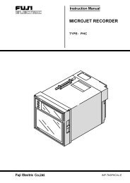
- Page 1: Instruction ManualMicro-controller
- Page 5 and 6: • If there is a danger of a serio
- Page 7 and 8: Standard : Vertical mounting, flush
- Page 9 and 10: IndexConfirming type specificationI
- Page 11 and 12: 2 WiringTerminal Connection Diagram
- Page 13 and 14: 4 Display and operationStandby mode
- Page 15 and 16: Operation/Standby modeSV indication
- Page 17 and 18: 6 Functions6-1 ON/OFF control• At
- Page 19 and 20: 6-3 Self-tuning1) At power on, chan
- Page 21 and 22: 6-4 Alarm function (option)1) Kinds
- Page 23 and 24: 6-5 Ramp/soak function [option]1. F
- Page 25 and 26: 6-7 Digital input (DI function) [op
- Page 27 and 28: 6-9 Retransmission function [option
- Page 29 and 30: 2Setting ofthe algorithm* Read if t
- Page 31 and 32: [Table 1] Input type codeParameter
- Page 33 and 34: [Table 4] Control output action mod
- Page 35 and 36: SpecificationPower voltage:100 (-15
- Page 37 and 38: Table of Contents1 Part Names and F
- Page 39 and 40: PXRdigit Specification Note45678910
- Page 41 and 42: 2 OperationsThis chapter explains h
- Page 43 and 44: Parameterdisplay symbolParameter na
- Page 45 and 46: Parameterdisplay symbolParameter na
- Page 47 and 48: 2-3 Parameter functions and method
- Page 49 and 50: Ramp-soak control (Settings: oFF/rU
- Page 51 and 52: Auto-tuning function (Settings: 0/1
- Page 53 and 54:
Setting alarm 1 and 2Upper limit of
- Page 55 and 56:
w Second block parametersProportion
- Page 57 and 58:
Derivative time (Setting range: 0.0
- Page 59 and 60:
Cooling-side proportional band coef
- Page 61 and 62:
Output offset value (Setting range:
- Page 63 and 64:
[Self-tuning]1 Function:With the se
- Page 65 and 66:
7 Reference [About the self-tuning
- Page 67 and 68:
HYS (Hysteresis) mode at ON/OFF con
- Page 69 and 70:
Cycle time of control output 2 (Coo
- Page 71 and 72:
Setting lower limit of the measurin
- Page 73 and 74:
Decimal point position (Settings: 0
- Page 75 and 76:
SV offset (Setting range: -50 to 50
- Page 77 and 78:
, Alarm types (Setting range: 0 to
- Page 79 and 80:
• Alarm codes with dual set value
- Page 81 and 82:
Ramp-soak status display (Display o
- Page 83 and 84:
• The segment in which both the r
- Page 85 and 86:
SV (Setting value) lower limiter (S
- Page 87 and 88:
[Setting example] Setting the delay
- Page 89 and 90:
, Options of alarm 1 and 2 (Setting
- Page 91 and 92:
[Description], Upper and lower limi
- Page 93 and 94:
, Output value display (Display onl
- Page 95 and 96:
Adjusting the PV (Measured value) d
- Page 97 and 98:
Starting the auto-tuning (DI functi
- Page 99 and 100:
Station No. for communication (Sett
- Page 101 and 102:
Input type for PYP (Setting range:
- Page 103 and 104:
Retransmission base scale (Setting
- Page 105 and 106:
3 TroubleshootingThis section expla
- Page 107 and 108:
Index72AAdjusting the PV display (0
- Page 109:
Safety Precaution● Before using t