DIFFERENTIAL PRESSURE - Coulton Instrumentation
DIFFERENTIAL PRESSURE - Coulton Instrumentation
DIFFERENTIAL PRESSURE - Coulton Instrumentation

You also want an ePaper? Increase the reach of your titles
YUMPU automatically turns print PDFs into web optimized ePapers that Google loves.
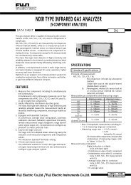
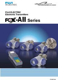
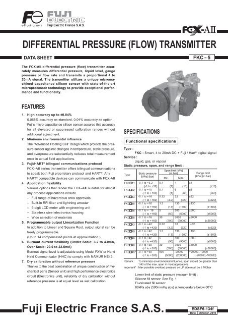
<strong>DIFFERENTIAL</strong> <strong>PRESSURE</strong> (FLOW) TRANSMITTERDATA SHEETFKC...5The FCX-AII differential pressure (flow) transmitter accuratelymeasures differential pressure, liquid level, gaugepressure or flow rate and transmits a proportional 4 to20mA signal. The transmitter utilizes a unique micromachinedcapacitance silicon sensor with state-of-the-artmicroprocessor technology to provide exceptional performanceand functionality.FEATURES1. High accuracy up to ±0.04%0.065% accuracy as standard, 0.04% accuracy as option.Fuji’s micro-capacitance silicon sensor assures this accuracyfor all elevated or suppressed calibration ranges withoutadditional adjustment.2. Minimum environmental influenceThe “Advanced Floating Cell” design which protects the pressuresensor against changes in temperature, static pressure,and overpressure substantially reduces total measurementerror in actual eld applications.3. Fuji/HART ® bilingual communications protocolFCX–AII series transmitter offers bilingual communicationsto speak both Fuji proprietary protocol and HART ® . AnyHART ® compatible devices can communicate with FCX-AII4. Application flexibilityVarious options that render the FCX–AII suitable for almostany process applications include.– Full range of hazardous area approvals– Built-in RFI lter and lightning arrester– 5-digit LCD meter with engineering unit– Stainless steel electronics housing– Wide selection of materials5. Programmable output Linearization FunctionIn addition to Linear and Square Root, output signal can befreely programmable.(Up to 14 compensated points at approximation.)6. Burnout current flexibility (Under Scale: 3.2 to 4.0mA,Over Scale: 20.0 to 22.5mA)Burnout signal level is adjustable using Model FXW or HandHeld Communicator (HHC) to comply with NAMUR NE43.7. Dry calibration without reference pressureThanks to the best combination of unique construction of mechanicalparts (Sensor unit) and high performance electronicscircuit (Electronics unit), reliability of dry calibration withoutreference pressure is at equal level as wet calibration.SPECIFICATIONSFunctional specificationsType :FKC : Smart, 4 to 20mA DC + Fuji / Hart ® digital signalService :Liquid, gas, or vapourStatic pressure, span, and range limit :TypeFKC 11FKC 22FKC 33FKC 35FKC 36FKC 38FKC 43FKC 45FKC 46FKC 48FKC 49*Static pressure[MPa] {bar}-0.1 to +3.2{-1 to +32}-0.1 to +10{-1 to +100}-0.1 to +16{-1 to +160}-0.1 to +16{-1 to +160}-0.1 to + 16{-1 to +160}-0.1 to +16{-1 to +160}-0.1 to +42{-1 to +420}-0.1 to +42{-1 to +420}-0.1 to +42{-1 to +420}-0.1 to +30{-1 to +300}-0.1 to +30{-1 to +300}Span limit [kPa]{m bar}Min. Max.0.1 1 ±1{1} {10}0.1 6 ±6{1} {60}0.32 32 ±32{3.2} {320}1.3 130 ±130{13} {1300}5500 ±500{50} {5000}30 3000 ±3000{300} {30000}0.32 32 ±32{3.2} {320}1.3 130 ±130{13} {1300}5500 ±500{50} {5000}30 3000{300} {30000}500 20000{5000} {200000}Range limit[kPa] {m bar}{±10}{±60}{±320}{±1300}{±5000}{±30000}{±320}{±1300}{±5000}±3000{±30000}+20000,-10000{+200000,-100000}Remark : To minimize environmental inuence, span should be greater than1/40 of the max. span in most applications.Important* : Max possible overload pressure on LP side must be 100barLower limit of static pressure (vacuum limit) ;Silicone ll sensor: See Fig. 1Fluorinated ll sensor:66kPa abs (500mmHg abs) at temperature below 60°CFuji Electric France S.A.S.EDSF6-134fDate October, 2010
FKC...5Over range limit :To maximum static pressure limitOutput signal :4 to 20mA DC (linear or square root) with digital signalsuperimposed on the 4 to 20mA signalPower supply :Transmitter operates on 10.5V to 45V DC at transmitterterminals.10.5V to 32V DC for the units with optional arrester.Load limitations : see gure belowLoad resistance[]2000150010005002500Note: For communication with HHC (1) (Model: FXW), min. of 250required.Hazardous locations :Authority(Digit 10= )ATEX(K)FactoryMutual(pending)(H)CSA(J)IECEx(T)1533600Operatingarea24V45V10 16.1 50 [ V ]10.5VIntrinsic safetyEx II 1 GEx ia IIC T5 (-40°C Ta +50 °C)Ex ia IIC T4 (-40°C Ta +70 °C)IP66/67Entity Parameters:Ui 28 Vdc, Ii 94.3 mA, Pi 0.66 WCi = 36 nF/26 nF for models with/without ArresterLi = 0.7 mH/0.6 mH for models with/without Analog IndicatorClass I II IIIDiv.1 Groups A, B, C, D, E, F, GT4 Entity Type 4XModel code9th digit 13th digitTambA,B,C,D,J Y,G,N -40°C to +85°CL,P,M,1,2,3 Y,G,N -20°C to +80°CQ,S,N,4,5,6 Y,G,N -20°C to +60°CE,F,G,H,K Y,G,N -40°C to +60°C- W,A,D -10°C to +60°CEntity Parameters:Vmax=42.4V, Imax=113mA, Pi=1W,Ci=35.98nF, Li=0.694mHEx ia Class I, Groups A, B, C and D;Class II, Groups E,F and G; Class IIIPer drawing TC 522873Temp. code T5 for Tamb max = +50°CTemp. code T4 for Tamb max = +70°CEntity Parameters:Vmax = 28 Vdc, Imax = 94.3 mA, Pmax = 0.66 WCi = 36 nF/25 nF for models with/without ArresterLi = 0.7 mH/0.6 mH for models with/without Analog IndicatorEx ia IIC T5 (-40°C Ta +50 °C)Ex ia IIC T4 (-40°C Ta +70 °C)IP66/67Entity Parameters:Ui 28 Vdc, Ii 94.3 mA, Pi 0.66 WCi = 36 nF/26 nF for models with/without ArresterLi = 0.7 mH/0.6 mH for models with/without Analog IndicatorAuthority(Digit 10= )ATEX(P)FactoryMutual(pending)(H)CSA(pending)(J)IECEx(Q)AuthorityATEX(X)FactoryMutual(pending)(D)CSA(E)IECEx(R)Ex II 3 GEx nA II T5 (-40°C Ta +70 °C)IP66/67Electrical ratingsModel Without arrester:Ui 45 Vdc, 4-20 mA loop powered, Pi 1.0125 WModel With arrester:Ui 32 Vdc, 4-20 mA loop powered, Pi 1.0125 WOptional Analog indicator is not available for type "n"Class I II IIIDiv.2 Groups A, B, C, D, F, GT4 Entity Type 4XClass IDiv.2 Groups A, B, C, DClass IIDiv.2 Groups E, F, GClass IIIDiv.2Temp Code T5 Tamb max = +50°CTemp Code T4 Tamb max = +70°CEntity Parameters:Vmax = 28 Vdc, Imax = 94.3 mA, Pmax = 0.66 WCi = 36 nF/25 nF for models with/without ArresterLi = 0.7 mH/0.6 mH for models with/without Analog IndicatorEx nA II T5 (-40°C Ta +70 °C)IP66/67Electrical ratingsModel Without arrester:Ui 45 Vdc, 4-20 mA loop powered, Pi 1.0125 WModel With arrester:Ui 32 Vdc, 4-20 mA loop powered, Pi 1.0125 WOptional Analog indicator is not available for type "n"Ex II 2 GDEx d IIC T6 (-40°C Ta +65 °C)Ex d IIC T5 (-40°C Ta +85 °C)Ex tD A21 IP66/67 T 85°CEx tD A21 IP66/67 T 100°CElectrical ratingsModel Without arrester:Ui 45 Vdc, 4-20 mA loop powered, Pi 1.0125 WModel With arrester:Ui 32 Vdc, 4-20 mA loop powered, Pi 1.0125 WClass IDiv.1 Groups B, C, DT6 Type 4XClass II IIIDiv.1 Groups E, F, GT6 Type 4XTamb max = +60°CType nNonincendiveModel code9th digit 13th digitTambA,B,C,D,J Y,G,N -40°C to +85°CL,P,M,1,2,3 Y,G,N -20°C to +80°CQ,S,N,4,5,6 Y,G,N -20°C to +60°CE,F,G,H,K Y,G,N -40°C to +60°C- W,A,D -10°C to +60°CFlameproofClass I, Groups C and D;Class II, Groups E,F and G ; Class IIIMaximum ambient temperature 85°CMaximum working pressure 50 MpaElectrical ratingsModel Without arrester:Ui 45 Vdc, 4-20 mAModel With arrester:Ui 32 Vdc, 4-20 mANote: "Seal not required"Ex d IIC T6 (-40°C Ta +65 °C)Ex d IIC T5 (-40°C Ta +85 °C)DIP A21 IP66/67 T 85°CDIP A21 IP66/67 T 100°CElectrical ratingsModel Without arrester:Ui 45 Vdc, 4-20 mA loop powered, Pi 1.0125 WModel With arrester:Ui 32 Vdc, 4-20 mA loop powered, Pi 1.0125 W2
Zero/span adjustment :Zero and span are adjustable from the HHC (1) . Zero andspan are also adjustable externally from the adjustmentscrew (span adjustment is not available with 9th digitcode “L, P, M, Q, S, N”).Damping :Adjustable from HHC (1) or local adjustment unit with LCDdisplay.The time constant is adjustable between 0 to 32 seconds.Zero elevation / suppression :-100% to +100% of URLNormal / reverse action :Selectable from HHC (1)Indication :Analog indicator or 5-digit LCD meter, as specied.Burnout direction : Selectable from HHC (1)If self-diagnostic detect transmitter failure, the analogsignal will be driven to either “Output Hold”, “OutputOverscale” or “Output Underscale” modes.“Output Hold” :Output signal is hold as the value just before failure happens.“Output Overscale” :Adjustable within the range 20.0mA to 22.5mA fromHHC (1)“Output Underscale” :Adjustable within the range 3.2mA to 4.0mA from HHC (1)Under scaleBurnout3.2 4 20 22.5 [mA]Over scaleBurnoutNormal operating rangeProbable under rangeProbable over rangeOutput limits conforming to NAMUR NE43 by order.Loop-check output :Transmitter can be congured to provide constant signal3.2mA through 22.5mA by HHC (1) .Temperature limit :Ambient : -40 to +85°C(-20 to +80°C for LCD indicator)(-40 to +60°C for arrester option)(-10 to +60°C for uorinated oil lled transmitters)For explosionproof units (ameproof or intrinsic safety),ambient temperature must be within the limits speciedin each standard.Process : -40 to +120°C for silicone ll sensor-20 to +80°C for uorinated oil ll sensorStorage : -40 to +90°CHumidity limit :0 to 100% RHCommunication :With HHC (1) (Model FXW, consult datasheet N° EDS8-47),following items can be remotely displayed or congured.Note: HHC’s version must be higher than 7.0(or FXW 1- 4), for FCX-AII. for supporting theseitems : “Saturate current”, “Write protect”, and “History”.ItemsFuji Protocolwith FXWHart ® ProtocolDisplay Set Display SetTag No. v v v vModel No. v v — —Serial No. & Software Version v — v —Engineering unit v v v vRange limit v — v —Measuring range v v v vDamping v v v vLinear v v v vOutput modeSquare root v v v vBurnout direction v v v vCalibration v v v vOutput adjust — v — vData v — v —Self diagnoses v — v —Printer (In case of FXW withprinter option)v — — —External switch lock v v v vTransmitter display v v v vLinearize* v v — —Rerange v v v vSaturate current v v v vWrite protect v v v vHistory– Calibration history– Ambient temperature history(Note) (1) HHC: Hand Held Communicator*Local configurator with LCD display (option) :Local congurator with 3 push button and LCD display cansupport all items (Fuji Protocol list) except “Linearize” function.Programmable output linearization function :Output signal can be characterized with “14 points linearapproximation function” from HHC (1) .Performance specifications for linear outputReference conditions, silicone oil ll, 316SS isolating diaphragms, 4 to20mA analog output in linear mode.Accuracy rating :(including linearity, hysteresis, and repeatability)Max span : 32kPa models and aboveFor spans greater than 1/10 of URL:±0.065% of span or ±0.04% of span (optional)For spans below 1/10 of URL:0.1 × URL± 0.015+0.05 % of spanvvSpanv—( )Max span 20MPa models :For spans greater than 5MPa :±0.1% of spanFor spans below 5MPa :5MPa±(0.05+0.05 % of spanSpan )Max span 1kPa, 6kPa models :For spans greater than 1/10 of URL:±0.1% of spanFor spans below 1/10 of URL :( )Stability :±0.1% of upper range limit (URL) for 10 years for 6th digitcode 3, 5, 6, 8 and 9.Temperature effect :Effects per 28°C change between the limits of -40°C and +85°Cvv0.1 × URL± 0.05+0.05 % of spanSpanRange code(6th digit in code Zero shiftTotal effectsymbols)“1”/1kPa {10mbar}±URL“2”/6kPa {60mbar}( 0.125+0.1 )%±URL( 0.15+0.1 ) %SpanSpan“3”/32kPa{320mbar}“5”/130kPa{1300mbar}URLURL± ( 0.075+0.0125“6”/500kPaSpan) % ± ( 0.095+0.0125Span ) %{5000mbar}“8”/3000 kPa{30000mbar}“9”/20000 kPa{200000mbar}Double the effects for material code (7th digit in codes symbols)“H”, “M”, “T”v—3
FKC...5Static pressure effect :4Static pressure code(5th digit in Code symbols)“1” / 1kPa {10mbar} sensor“2” / 6kPa {60mbar} sensor“3”, “4”“4”Overrange effect :Static pressure code(5th digit in Code symbols)“1” / 1kPa {10mbar} sensor“2” / 6kPa {60mbar} sensor“3”“3”“4”“4”Zero shift(% of URL)±0.2% / 2MPa {20bar}±0.2% / 3.2MPa {32bar}±0.035% / 6.9MPa {69bar}±0.2% / 6.9MPa {69bar} FKC49Double the effects for material code (7th digit in codes symbols)“H”, “M”, “T”Zero shift (% of URL)±0.3% / 2MPa {20bar}±0.1% / 3.2MPa {32bar}±0.1% / 16MPa {160bar} FKC35,36,38±0.15% / 16MPa {160bar} FKC33±0.25% / 42MPa {420 bar} FKC33,35,36,38±0.2% / 10MPa {100 bar} FKC49Double the effects for material code (7th digit in codes symbols)“H”, “M”, “T”Supply voltage effect :Less than 0.005% of calibrated span per 1VUpdate rate : 60 msecResponse time : (at 63,2% of output signal)Performance specifications for square root outputAccuracy rating:Output50 to 100%20 to 50%10 to 20%Range code(6th digit in code symbols)over 0.1 × URL±0.065 %±0.163 %±0.325 %Max span 1kPa, 6kPa model:Output50 to 100%20 to 50%10 to 20%Time constant(at 23°C)“1” 0.33 s“2” 0.3 s“3” 0.12 s“5” through “8” 0.08 sAccuracy±0.1 %±0.25%±0.5 %Dead time0.12 sResponse time = time constant + dead timeMounting position effect :Zero shift, less than 0.12kPa {1.2m bar} for a 10° tilt inany plane.No effect on span.This error can be corrected by adjusting Zero.Vibration effect :> ±0,25% Of span for spans greater than 1/10 of URL.Frequency 10 to 150Hz, acceleration 39,2m/sec 2 .Material fatigue :Please consult Fuji Electric.Dielectric strength :500V AC, 50/60Hz 1 min., between circuit and earth.Insulation resistance :More than 100M at 500V DC.Internal resistance for external field indicator :12 max. (connected to test terminal CK+ and CK-)Spanbelow 0.1 × URL±(0.015+0.05 × 0.1 × URL/Span)%±2.5 × (0.015+0.05 × 0.1 × URL/Span)%±5 × (0.015+0.05 × 0.1 × URL/Span)%Temperature effect:Effects per 28°C change between the limits of -40°Cand +85°CRange code“1” and “2”“3” through “9”Low flow cut-off:Customer congurable for any point between 0 to 20% ofoutputPhysical specificationsElectrical connections:1/2”-14 NPT, Pg13.5 or M20×1.5Process connections:1/4”-18 NPT on 54mm centers, as specied.Meets DIN 19213.option: 1/2”-14 NPT for oval angesProcess-wetted parts material:Material code(7th digit incode symbols)VWHJMTProcesscover316L SS(*1)316L SS(*1)316L SS(*1)316L SS(*1)316L SS(*1)316L SS(*1)Shift at 20% output point( )URL± 0.375+0.25 %/28°CSpanURL± ( 0.24+0.03125 )%/28°CSpanDiaphragm316L SSHastelloy-CHastelloy-C316L SS +Gold coatingMonelTantalumWettedsensor body316/31803 SS316 SSHastelloy-Clining316SSMonel liningTantalum liningVent/drain316 SS316 SS316 SS316 SS316 SS316 SSNotes: *(1) ASTM CF8MRemark:Sensor gasket :Viton o-ring or PTFE square section gasket. Availabilityof above material design depends on ranges and static pressure.Refer to “Code symbols”.Non-wetted parts material :Electronics housing:Low copper die-cast aluminum alloy nished with polyestercoating (standard), or 316 stainless steel, as specied.Bolts and nuts:• Cr-Mo alloy (standard) till 420 bar,• 316 stainless steel for static pressure if 160 bar max.• SS660 for static pressure > 160 bar.Fill uid :Silicone oil (standard) or uorinated oilMounting bracket :304 stainless steelEnvironmental protection:IEC IP67 and NEMA 6/6PMounting:Without mounting bracket : direct mounting on mani-fold(optional)With optional mounting bracket : for 50mm (2”) pipe ordirect wall mounting.Mass{weight}:Transmitter approximately 3.1 to 3.6kg without options.Add; 0.5kg for mounting bracket4.5kg for stainless steel housing (option)
FKC...5OUTLINE DIAGRAM (unit: mm) Earth terminal4th of code symbols"M, N, P, R, T, V, W, X"type is not attached"B" Conduit connec.Withananalog indicatorWith digital indicatorOval flange screwSee table 1Zero/Spanadjustment screwSide vent(option)"A" Press. conn.Vent/drainplugPipe MountingU-bolt M84 holes Ø9ø18.5Gø15E8 2.5ø7DDetails of "A"Details of "B"DEGRM20x1.5161/4-18 NPT7/16-20UNFT1/2-14NPT161/4-18 NPT7/16-20UNFVPg13.510,51/4-18 NPTM10 or M12WM20x1.5161/4-18 NPTM10 or M12XPg13.510,51/4-18 NPT7/16-20UNF8
FKC...5CONNECTION DIAGRAMFuji ElectricYour distributor:<strong>Coulton</strong> <strong>Instrumentation</strong> Ltd17 Somerford Business Park, Christchurch, BH23 3RU, UKTel: +44 1202 480 303E-mail: sales@coulton.com Web: www.coulton.comFuji Electric can accept no responsibility for possible errors in catalogues, brochures and other printed material. Fuji Electric reserves the right to alter its productswithout notice. This also applies to products already on order provided that such alterations can be made without subsequential changes being necessaryin specications already agreed. All trademarks in this material are property of the respective companies. All rights reseved.