Infrared gas analyzer Type ZKJ - Coulton
Infrared gas analyzer Type ZKJ - Coulton
Infrared gas analyzer Type ZKJ - Coulton

Create successful ePaper yourself
Turn your PDF publications into a flip-book with our unique Google optimized e-Paper software.
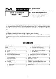
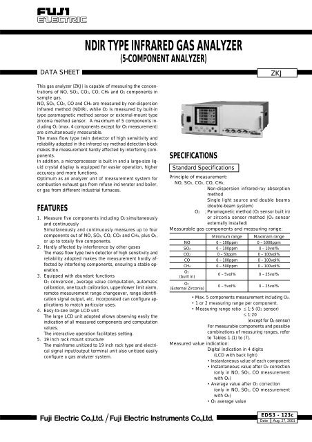
DATA SHEETNDIR TYPE INFRARED GAS ANALYZER(5-COMPONENT ANALYZER)<strong>ZKJ</strong>This <strong>gas</strong> <strong>analyzer</strong> (<strong>ZKJ</strong>) is capable of measuring the concentrationsof NO, SO2, CO2, CO, CH4 and O2 components insample <strong>gas</strong>.NO, SO2, CO2, CO and CH4 are measured by non-dispersioninfrared method (NDIR), while O2 is measured by built-intype paramagnetic method sensor or external-mount typezirconia method sensor. A maximum of 5 components includingO2 (max. 4 components except for O2 measurement)are simultaneously measurable.The mass flow type twin detector of high sensitivity andreliability adopted in the infrared ray method detection blockmakes the measurement hardly affected by interfering components.In addition, a microprocessor is built in and a large-size liquidcrystal display is equipped for easier operation, higheraccuracy and more functions.Optimum as an <strong>analyzer</strong> unit of measurement system forcombustion exhaust <strong>gas</strong> from refuse incinerator and boiler,or <strong>gas</strong> from different industrial furnaces.FEATURES1. Measure five components including O2 simultaneouslyand continuouslySimultaneously and continuously measures up to fourcomponents out of NO, SO2, CO, CO2 and CH4, plus O2,or up to totally five components.2. Hardly affected by interference by other <strong>gas</strong>esThe mass flow type twin detector of high sensitivity andreliability adopted makes the measurement hardly affectedby interfering components, ensuring a stable operation.3. Equipped with abundant functionsO2 conversion, average value computation, automaticcalibration, one touch calibration, upper/lower limit alarm,remote measurement range changeover, range identificationsignal output, etc. incorporated can configure applicationsto match particular uses.4. Easy-to-see large LCD unitThe large LCD unit adopted allows observing easily theindication of all measured components and computationvalues.The interactive operation facilitates setting.5. 19 inch rack mount structureThe mainframe unitized to 19 inch rack type and electricalsignal input/output terminal unit also unitized easilyconfigure a <strong>gas</strong> <strong>analyzer</strong> system.SPECIFICATIONSStandard SpecificationsPrinciple of measurement:NO, SO2, CO2, CO, CH4;Non-dispersion infrared-ray absorptionmethodSingle light source and double beams(double-beam system)O2 ; Paramagnetic method (O2 sensor built in)or zirconia sensor method (O2 sensorexternally installed)Measurable <strong>gas</strong> components and measuring range:NOSO2CO2COCH4O2(built in)O2(External Zirconia)Minimum range0 – 100ppm0 – 100ppm0 – 50ppm0 – 100ppm0 – 500ppm0 – 5vol%0 – 5vol%Maximam range0 – 5000ppm0 – 10vol%0 – 100vol%0 – 100vol%0 – 100vol%0 – 25vol%0 – 25vol%• Max. 5 components measurement including O2.• 1 or 2 measuring range per component.• Measuring range ratio ≤ 1:5 (O2 sensor)≤ 1:20(except for O2 sensor)For measurable components and possiblecombinations of measuring ranges, referto Tables 1-(1) to (7).Measured value indication:Digital indication in 4 digits(LCD with back light)• Instantaneous value of each component• Instantaneous value after O2 correction(only in NO, SO2, CO measurementwith O2)• Average value after O2 correction(only in NO, SO2, CO measurementwith O2)• O2 average valueEDS3 - 123cDateAug. 27, 2001
<strong>ZKJ</strong>2Analog output signals:* Inputs/outputs of analog signals arepossible by combining with the input/output terminal module.4 to 20mA DC or 0 to 1V DC,non-isolated output ; 12 points max.Analog output corresponds to measuredvalue indication in 1:1.Permissible load resistance;550Ω max. for 4 to 20 mADC100kΩ min. for 0 to 1V DC* Refer to Table 2, for the channel No. ofdisplayed values and analog output signals.Analog input signal:For signal input from externally installedO2 sensor.Signal requirement;(1) Signal from Fuji's Zirconia O2 sensor(TYPE: ZFK7)(2) 0 to 1V DC from an O2 sensorInput section is not isolated. This featureis effective when an O2 sensor is notbuilt in.(An input signal triggers measured concentrationindication and O2 conversion.)Relay contact output:1a contact (250V AC/2A, resistive load)Instrument error, calibration error,range discrimination, auto calibrationstatus and maintenance status, pumpON/OFF, peak alarm.1c contact (250V AC/2A, resistive load)Upper/lower alarm contact output.(for each channel)Power disconnection alarm.* All relay contacts are isolated mutuallyand from the internal circuit.Contact input: No-voltage contact (ON/0V, OFF/5VDC, 5mA flowing at ON)Remote range changeover, auto calibrationremote start, remote holding,average value resetting, pump ON/OFFIsolated from the internal circuit withphotocoupler. Contact inputs are not isolatedfrom one another.Transmission output:Solenoid valve drive signal for automaticcalibration.Transistor output (100mA or less)Rated operating conditions:Power supply; 85 to 264 V AC, 50/60Hz(3-pin inlet terminal used)Power consumption; 150VAAmbient temperature; -5˚C to 45˚CAmbient humidity; 90% RH max.Storage conditions:Ambient temperature; -20˚C to 60˚CAmbient humidity; 100% RH max., noncondensingDimensions (H x W x D):Analyzer main unit;177 x 483 x 690mmInput/output terminal module;164 x 318 x 55mmMass:Approx. 22 kg (only Analyzer)Finish color: Front panel; Off-white (Munsell 10Y7.5/0.5 or equivalent)Casing; Plating, Steel-blue (gray)Enclosure: Steel casing, for indoor useMaterial of <strong>gas</strong>-contacting parts:Gas inlet/outlet; SUS304Sample cell; SUS304/neoprene rubber<strong>Infrared</strong>-ray transmitting window; CaF2O2 sensor sampling cell : SUS316Internal piping; Toaron tube, Teflon tubeGas inlet/outlet: Rc 1 /4 or NPT 1 /4 internal threadPurge <strong>gas</strong> flow rate:1L/min ( when required)Standard FunctionsOutput signal holding:Output signals are held during manual andauto calibrations by activation of holding(turning "ON" its setting).The values to be held are the ones justbefore start calibration mode.Indication values will not be held.Remote output holding:Output signal is held at the latest valueby short-circuiting the remote outputholding input terminals.Holding is maintained while the terminalsare short-circuited. Indication values willnot be held.Remote range changeover:Measuring range can be changed accordingto an external signal when remoterange changeover input is received.Changeover is effective only when remoterange setting is turned on. In thiscase, measuring range cannot be changedmanually.When the contact input terminals for eachcomponent are short-circuited, the firstrange is selected, and it is changed overto the second range when the terminalsare open.Range identification signal:The present measuring range is identifiedby a contact signal.The contact output terminals for eachcomponent are short-circuited when thefirst range is selected, and when the secondrange is selected, the terminals areopen.Auto calibration:Auto calibration is carried out periodicallyat the preset cycle.When a standard <strong>gas</strong> cylinder for calibrationand a solenoid valve for opening/closingthe <strong>gas</strong> flow line are prepared externallyby the customer, calibration will becarried out with the solenoid valve drivecontacts for zero calibration and each spancalibration turned on/off sequentially atthe set auto calibration timing.Auto calibration cycle setting:Auto calibration cycle is set.Setting is variable within 1 to 99 hours(in increments of 1 hour) or 1 to 40 days(in increments of 1 day).Gas flow time setting:The time for flowing each calibration <strong>gas</strong>in auto calibration is set.Settable within 60 to 599 seconds (in incrementsof 1 second)
Auto calibration remote start:Auto calibration is carried out only onceaccording to an external input signal. Calibrationsequence is settable in the sameway as the general auto calibration.Auto calibration is started by opening theauto calibration remote start input terminalsafter short-circuiting for 1.5 secondsor longer.Auto zero calibration:Auto zero calibration is carried out periodicallyat the preset cycle.This cycle is independent on "Autocalibradion" cycle.When zero calibration <strong>gas</strong> and solenoidvalve for opening/closing the calibration<strong>gas</strong> flow line are prepared externally bythe customer, zero calibration will becarried out with the solenoid valve drivecontact for zero calibration turned on/offat the set auto zero calibration timing.Auto zero calibration cycle setting:Auto zero calibration cycle is set.Setting is variable within 1 to 99 hours(in increments of 1 hour) or Setting isvariable within 1 to 40 days (in incrementsof 1 day)Gas flow time setting:The timing for flowing zero <strong>gas</strong> in autozero calibration is set.Settable 60 to 599 seconds (in incrementsof 1 second)Upper/lower limit alarm:Alarm contact output turns on whenmeasurement value reach to the presetupper or lower limit alarm value.Contacts close when the instantaneousvalue of each component becomes largerthan the upper alarm limit value or smallerthan the lower alarm limit value.Instrument error contact output:Contacts close at occurrence of <strong>analyzer</strong>error No. 1, 3 or 10.Calibration error contact output:Contacts close at occurrence of manualor auto calibration error (any of errors No.4 to 9).Auto calibration status and maintenance status contactoutputs: Contacts close during auto calibration andduring input of the remote hold signal.Pump ON/OFF contact output:During measurement, this contact close.While calibration <strong>gas</strong> is flowing, this contactopen. This contact is connected inpower supply of pump, and stop thesample <strong>gas</strong> while calibration <strong>gas</strong> flowing.Optional FunctionsO2 correction: Conversion of measured NO, SO2 and CO<strong>gas</strong> concentrations into values at standardO2 concentration21–OnCorrection formula: C = –––––––– x Cs21–OsC : Sample <strong>gas</strong> concentration after O2correctionCs : Measured concentration of sample<strong>gas</strong>Os : Measured O2 concentrationOn: Standard O2 concentration (valuechangeable by setting)*The upper limit value of the fractionalpart in this calculation is 4.The result of calculation is indicated andoutput in an analog output signal.Average value after O2 correction and O2 average valuecalculation: The result of O2 correction or instantaneousO2 value can be outputted as anaverage value in the determined periodof time.Used for averaging is the moving averagemethod in which sampling is carriedout at intervals of 30 seconds.(Output is updated every 30 seconds. Itis the average value in the determinedperiod of time just before the latest updating.)Averaging time is settable within 1 to 59minutes (in increments of 1 minute) or 1to 4 hours (in increments of 1 hour).Average value resetting:The above-mentioned output of averagevalue is started from the initial state byopening the average value resetting inputterminals after short-circuiting for 1.5seconds or longer.Output is reset by short-circuiting andrestarted by opening.CO concentration peak count alarm:(added only for CO/O2 measurement)Alarm output turns on according to thepreset concentration and count.Whenever the instantaneous value of COexceeds the preset concentration value,count increments. If the count exceedsthe preset value in one hour, the alarmcontacts close.Communication function:RS-232C (9pins D-sub)Half-duplex bit serialStart-stop synchronizationModbus TM protcolContents: Read/Wright parametersRead measurement concentrationand instrument statusRemark: When connecting via RS-485interface, a RS-232C RS-485 converter should be used.PerformanceRepeatability : ± 0.5% of full scaleLinearity : ± 1% of full scaleZero drift : ± 2% of full scale/weekSpan drift : ± 2% of full scale/weekResponse time :(for 90% FS response)Within 60 seconds including replacementtime of sample <strong>gas</strong> (when <strong>gas</strong> flow rateis 0.5L / min)3
<strong>ZKJ</strong>Standard Requirements for Sample GasFlow rate : 0.5L / min ± 0.2L / minTemperature : 0 to 50˚CPressure : 10 kPa or less (Gas outlet side should beopen to the atmospheric air.)Dust : 100µg/Nm 3 or less in particle size of 1µmor lessMist: UnallowableMoisture : Below a level where saturation occurs at2˚C (condensation unallowable).Corrosive component:HCl 1 ppm or lessStandard <strong>gas</strong> for calibration:Zero <strong>gas</strong> ; Dry N2Span <strong>gas</strong> ; Each sample <strong>gas</strong> having concentration90 to 100% of itsmeasuring range (recommended).Gas beyond concentration100%FS is unusable.In case a zirconia O2 <strong>analyzer</strong> is installedexternally and calibration is carried out onthe same calibration <strong>gas</strong> line:Zero <strong>gas</strong> ; Dry air or atmospheric air(provided without CO2 sensor)Span <strong>gas</strong> ; For other than O2 measurement,each sample <strong>gas</strong> havingconcentration 90 to 100%of its measuring range.For O2 measurement, O2 <strong>gas</strong>of 1 to 2 vol%.Installation Requirements• Select a place where the equipment does not receive directsunshine, draft/rain or radiation from hot substances.If such a place cannot be found, a roof or cover should beprepared for protection.• Avoide a place where receives heavy vibration• Select a place where atmospheric air is cleanPrinciple diagram of NDIR type measurement (For NO, SO2, CO2, CO, CH4)MotorDistribution cell(interference filter)TrimmerReference cellInterference compensatingdetectorRotary sectorSectorsync. signal<strong>Infrared</strong> (single)light sourceSample <strong>gas</strong>inletO2 sensorSample cellSample <strong>gas</strong>outletAC amplifierGain changeover(option)A/DCPURAMROMExternal input / Contact outputD/AIndicatorOutput0 to 1V or4 to 20mA DCOperating keysIndication4
Principle diagram of paramagnetic type measurement (For O2)PermanentmagnetMirrorGas inletMagnetic fieldMeasuringcellGas outletPreamplifierPermanentmagnetLEDPhotodiodeIndicationSignal processingand calculation blockOutputExample configuration of <strong>gas</strong> sampling systemThe following illustrates a typical system configuration for five component <strong>gas</strong> measurement for monitoring combustionexhaust <strong>gas</strong> from boiler, refuse incinerator, etc.Contact FUJI ELECTRIC for system configuration matching the particular use or further information.1 Gas extractorAC100V15˚ or largerGas inlet tube3 Gas aspirator4Electronic<strong>gas</strong> cooler6 Membrane filter7 Flowmeter10 NO2/NOconverterfor NOxmeasurement6 MembranefilterCO, CO2(O2)<strong>Infrared</strong> <strong>gas</strong><strong>analyzer</strong> mainunitNO, SO22 Gas conditionerGas outletZERONOSO2CO2CO5 SolenoidvalveO2Pressurereducing valveO2N2orAirNO/N2SO2/N2CO2/N2CO/N2O2/N29ZirconiaO2 sensorDrain(Note 2)8Standard <strong>gas</strong> (3.4r)Functions of Individual Components1 Gas extractor: Gas extractor with a heating typestainless steel filter of standard mesh40µm2 Gas conditioner:For separation of drain, prevention of drainfrom being sucked through secondaryfilter and composite operation of constantpressurebubbler3 Gas aspirator: For aspiration of sample <strong>gas</strong> (sample<strong>gas</strong> flow rate approx. 2L/min)4 Electronic <strong>gas</strong> cooler:Dries the moisture in sample <strong>gas</strong> to a dewpoint of approx. 3˚C.5 Solenoid valve: Used for introducing calibration <strong>gas</strong>.6 Membrane filter:PTFE filter used to eliminate fine dust particlesand permit monitoring of dust adheringcondition on the front panel of the<strong>gas</strong> <strong>analyzer</strong>.7 Flowmeter: Adjusts and monitors the flow rate ofsample <strong>gas</strong>.8 Standard <strong>gas</strong>: Reference <strong>gas</strong> used for calibrating zeroand span of the <strong>analyzer</strong>. Total 6 cylindersrequired for air, zero <strong>gas</strong>, span <strong>gas</strong>NO, SO2, CO, CO2 and O2.9 Zirconia O2 sensor:(This is not necessary in case when thezirconia type O2 sensor is built-in.)External zirconia oxygen sensor used formeasuring the oxygen concentration (0to 25%) in sample <strong>gas</strong>.10 Converter: Added to NOx <strong>analyzer</strong>.A special catalyst material for efficientconversion of NO2 <strong>gas</strong> to NO is used.*(Note)For each <strong>gas</strong> sampling device, refer to the separateData Sheet for each <strong>gas</strong> sampling device.5
<strong>ZKJ</strong>CODE SYMBOLSDigit456789101112DescriptionStandard1st 2nd 3rd 4thcomponet componet componet componetNOSO2CO2COCH4NO SO2NO COCO2 CONO SO2 CONO SO2 CO2 CONoneExternal zirconia type O2 sensor (Model : ZFK7)External O2 <strong>analyzer</strong>Built-in paramagnetic type O2 sensor85 to 264V AC, Rc1/485 to 264V AC, Rc 1 /4, with purging85 to 264V AC, NPT1/485 to 264V AC, NPT 1 /4, with purging19-inch rack mounting type19-inch rack mounting type with slide railIn JapaneseIn English 1st component, 1st range0 to 50ppm0 to 100ppm0 to 200ppm0 to 250ppm0 to 500ppm0 to 1000ppm0 to 2000ppm0 to 5000ppm0 to 1%0 to 2%0 to 3%0 to 5%0 to 10%0 to 20%0 to 40%0 to 50%0 to 70%0 to 100% 1st component, 2nd rangeNone0 to 100ppm0 to 200ppm0 to 250ppm0 to 500ppm0 to 1000ppm0 to 2000ppm0 to 5000ppm0 to 1%0 to 2%0 to 3%0 to 5%0 to 10%0 to 20%0 to 40%0 to 50%0 to 70%0 to 100%notenote 1note 7note 2note 6note 2note 61 2 3<strong>ZKJ</strong>4 5 6 7FPADBEFHGLMYABC012328 9 10 11 12 13 14 15 16 17 18 19 20 21 22 23 Digit No.of code(note1) External O2 sensor signal should be 0-1VDC linear of full scale, when “ B ” is specified at the 6th digit.External Zirconia O2 sensor and external O2 <strong>analyzer</strong> are not included in this order.(note2) Allowable combinations of ranges are specified in the table 1-(1) to 1-(7) in page 9 and 10.BCJEABCDEFGHJKQLMNWPXRYBCDEFGHJKQLMNWPXR6
Digit13141516Description 2nd component, 1st rangeNone0 to 100ppm0 to 200ppm0 to 250ppm0 to 500ppm0 to 1000ppm0 to 2000ppm0 to 5000ppm0 to 1%0 to 2%0 to 3%0 to 5%0 to 10%0 to 20%0 to 40%0 to 50%0 to 70%0 to 100% 2nd component, 2nd rangeNone0 to 200ppm0 to 250ppm0 to 500ppm0 to 1000ppm0 to 2000ppm0 to 5000ppm0 to 1%0 to 2%0 to 3%0 to 5%0 to 10%0 to 20%0 to 40%0 to 50%0 to 70%0 to 100% 3rd component, 1st rangeNone0 to 100ppm0 to 200ppm0 to 250ppm0 to 500ppm0 to 1000ppm0 to 2000ppm0 to 5000ppm0 to 1%0 to 2%0 to 3%0 to 5%0 to 10%0 to 20%0 to 40%0 to 50%0 to 70%0 to 100% 3rd component, 2nd rangeNone0 to 200ppm0 to 250ppm0 to 500ppm0 to 1000ppm0 to 2000ppm0 to 5000ppm0 to 1%0 to 2%0 to 3%0 to 5%0 to 10%0 to 20%0 to 40%0 to 50%0 to 70%0 to 100%notenote 2note 2note 2note 21 2 3<strong>ZKJ</strong>4 5 6 7(note2) Allowable combinations of ranges are specified in the table 1-(1) to 1-(7) in page 9 and 10.8 9 10 11 12 13 14 15 16 17 18 19 20 21 22 23 Digit No.of codeYBCDEFGHJKQLMNWPXRYCDEFGHJKQLMNWPXRYBCDEFGHJKQLMNWPXRYCDEFGHJKQLMNWPXR7
<strong>ZKJ</strong>Digit17181920212223Description 4th component, 1st rangeNone0 to 100ppm0 to 200ppm0 to 250ppm0 to 500ppm0 to 1000ppm0 to 2000ppm0 to 5000ppm0 to 1%0 to 2%0 to 3%0 to 5%0 to 10%0 to 20%0 to 40%0 to 50%0 to 70%0 to 100% 4th component, 2nd rangeNone0 to 200ppm0 to 250ppm0 to 500ppm0 to 1000ppm0 to 2000ppm0 to 5000ppm0 to 1%0 to 2%0 to 3%0 to 5%0 to 10%0 to 20%0 to 40%0 to 50%0 to 70%0 to 100%None0 to 5%0 to 10%0 to 25%None0 to 10%0 to 25%4 to 20mA DC0 to 1V DC4 to 20mA DC + Commnication function0 to 1V DC + Commnication functionNoneWith O2 correction outputWith peak alarmWith O2 correction output and peak alarmFor combustion exhaust <strong>gas</strong>Othersnotenote 2note 2note 3note 4note 51 2 3<strong>ZKJ</strong>4 5 6 78 9 10 11 12 13 14 15 16 17 18 19 20YBCDEFGHJKQLMNWPXRYCDEFGHJKQLMNWPXRYLMVYMV21 22 23 Digit No.of codeABCDYABCBZ(note1) External O2 sensor signal should be 0-1VDC linear of full scale, when “ B ” is specified at the 6th digit.External Zirconia O2 sensor and external O2 <strong>analyzer</strong> are not included in this order.(note2) Allowable combinations of ranges are specified in the table 1-(1) to 1-(7) in page 9 and 10.(note3) O2 correction is carried out for CO, SO2 and NO. At the same time, average value output after O2 correctionand O2 average value output are added. Peak count alarm is carried out for CO.(note4) “ Y ” should be specified when without O2 measurement (when 6th digit is Y).(note5) A <strong>gas</strong> composition table should be issued when “ Z ” is specified.(note6) Only O2 sensor can be specified.(note7) When specifying the 3-and 4-component <strong>analyzer</strong> for purging, only one set of <strong>gas</strong> inlet / outlet is provided.The NO2/NO converter cannot be arranged between the <strong>gas</strong> inlet and outlet.8
Table 1. Measurable component and range – availability check table –(1) Single-component <strong>analyzer</strong> (NO, SO2, CO2, CO or CH4): CO <strong>analyzer</strong> measurable range : CH4 <strong>analyzer</strong> measurable range2nd range BCDEFG1st range0 to 100ppm 0 to 200ppm 0 to 250ppm 0 to 500ppm 0 to 1000ppm 0 to 2000ppmABC 0 to 200ppmD 0 to 250ppmEFGH0 to 50ppm0 to 100ppm0 to 500ppm0 to 1000ppm0 to 2000ppm0 to 5000ppmJ 0 to 1%K 0 to 2%Q 0 to 3%L 0 to 5%M 0 to 10%N 0 to 20%W 0 to 40%P 0 to 50%X 0 to 70%R 0 to 100%: NO <strong>analyzer</strong> measurable range : SO2 <strong>analyzer</strong> measurable range : CO2 <strong>analyzer</strong> measurable range––––––––––––––––––––––––––––––––––––––––––––––––––––––––––––––––––––––––––––––––––––––––––––––––––––––––––––––––––––––––––––––––––––––––––––––––––––––––––––––––––––––––––––––––––––––––––––––––––––––––––––––––––––––––––––––––––––––––––––––––––––––––––––––––––––––––H0 to 5000ppm––––––––––––––––––––––––––––––––––––––––––J0 to 1%––––––––––––––––––––––––––––––––––––––––––K0 to 2%––––––––––––––––––––––––––––––––––––––––––2nd range1st rangeA 0 to 50ppmB 0 to 100ppmC 0 to 200ppmD 0 to 250ppmE 0 to 500ppmF 0 to 1000ppmG 0 to 2000ppmH 0 to 5000ppmJ 0 to 1%K 0 to 2%Q 0 to 3%L 0 to 5%M 0 to 10%N 0 to 20%W 0 to 40%P 0 to 50%X 0 to 70%R 0 to 100%QLMNW P X R0 to 3% 0 to 5% 0 to 10% 0 to 20% 0 to 40% 0 to 50% 0 to 70% 0 to 100%––– ––– ––– ––– ––– ––– ––– –––––– ––– ––– ––– ––– ––– ––– –––––– ––– ––– ––– ––– ––– ––– –––––– ––– ––– ––– ––– ––– ––– –––––– ––– ––– ––– ––– ––– ––– –––––– ––– ––– ––– ––– ––– ––– –––––– ––– ––– ––– ––– ––– –––––– ––– ––– ––– –––––– ––– ––– –––––– ––– ––––––––––––––––––––––––––––––––––––––––––––––––––––––––––––––––––––––––––––––––––––––––––––––––––––––––––––––––––(2) Double-component <strong>analyzer</strong> (NO and SO2 ): Double components measurable range. 1st component ; NO, 2nd component ; SO2.2nd component (SO2), 1st rangeSO21st component BCDEFGH(NO),1st range 0 to 100ppm 0 to 200ppm 0 to 250ppm 0 to 500ppm 0 to 1000ppm 0 to 2000ppm 0 to 5000ppmB 0 to 100ppm–––C 0 to 200ppm–––D 0 to 250ppm–––NOE 0 to 500ppmF 0 to 1000ppmG 0 to 2000ppm9
<strong>ZKJ</strong>(3) Double-component <strong>analyzer</strong> (NO and CO): Double components measurable range. 1st component ; NO, 2nd component ; CO.2nd component (CO), 1st rangeCO1st component(NO),1st rangeB0 to 100ppmC0 to 200ppmD0 to 250ppmE0 to 500ppmF0 to 1000ppmG0 to 2000ppmH0 to 5000ppmB 0 to 100ppm–––C 0 to 200ppm–––D 0 to 250ppm–––NOE 0 to 500ppmF 0 to 1000ppmG 0 to 2000ppm(4) Double-component <strong>analyzer</strong> (CO2 and CO): Double components measurable range. 1st component ; CO2, 2nd component ; CO.2nd component (CO), 1st rangeCO1st component(CO2),1st rangeB0 to 100ppmC0 to 200ppmD0 to 250ppmE0 to 500ppmF0 to 1000ppmG0 to 2000ppmH0 to 5000ppmG 0 to 2000ppmH 0 to 5000ppmJ 0 to 1%CO2 K 0 to 2%L 0 to 5%M 0 to 10%––––––––––––––––––––––––––––––––– –––N 0 to 20%* The interpretation of measurable range of double-component <strong>analyzer</strong> in (2), (3) and (4) is as follows.First select the first range of respective components. Available if .This is all you have to do unless the second range is necessary. If the second range is necessary, it must begreater than and, smaller than 20 times, the first range, and, CO2 and CO <strong>analyzer</strong> must meet the measurablecombination of components in Table (1).J0 to 1%(5) Three-component <strong>analyzer</strong> (NO, SO2 and CO)NO/SO2 <strong>analyzer</strong> must meet the combination range in Table 1-(2): Double-component <strong>analyzer</strong>. CO <strong>analyzer</strong> must meetthe range in Table 1-(1): Single component <strong>analyzer</strong>.(6) Four-component <strong>analyzer</strong> (NO, SO2, CO2 and CO)NO/SO2 <strong>analyzer</strong> must meet the combination range in Table 1-(2): Double-component <strong>analyzer</strong>. CO2/CO <strong>analyzer</strong> mustmeet the range in Table 1-(4): Double-component <strong>analyzer</strong>.(7) O2 <strong>analyzer</strong>: Built-in O2 <strong>analyzer</strong> measurable range,: External zirconia type O2 <strong>analyzer</strong> measurable range2nd range1st rangeM0 to 10%V0 to 25%L 0 to 5%M 0 to 10% –––V 0 to 25% –––*O2 <strong>analyzer</strong> is selectable indifferently to combination withother components.External zirconia type O2 <strong>analyzer</strong> is assumed to be Fuji’s type ZFK7.10
MODEESCENTZEROSPANOUTLINE DIAGRAM (Unit: mm)M4(for mounting slide rail)(24)12.7123.8288.9690 or less466.738Power switchINFRARED GAS ANALYZERSample <strong>gas</strong> outlet Rc1/4 or NPT1/426.1POWERSample <strong>gas</strong> inlet Rc1/4 or NPT1/4(Purge <strong>gas</strong> inlet Rc1/4 or NPT1/4)DISPLAY7.5100.8465483Switch for Back Light429177Connector for input/outputterminal modulePower inlet11
<strong>ZKJ</strong>(Accessory)Mounting hole6-φ4.5hole316150 150 8(54.5)29(140) 12164154 5TerminalblockTerminalblockTerminalblockTerminalblockTerminalblockScrew terminals M3.5Input / output terminalmodule connector(280)8Connector(Accessory)1000±30M4 screw150 150154142302Cut M4 screw holes at 6 positions.Drill a rectangular hole of 302 142mm or more in the center.12
<strong>ZKJ</strong>EXTERNAL CONNECTION DIAGRAMCH5 output –(CH5_OUT) +CH4 output(CH4_OUT)CH3 output(CH3_OUT)CH2 output(CH2_OUT)CH1 output(CH1_OUT)–+–+–+–+Terminal block 11234567811121314151617189 1910 20(M3.5 screw)–+–+–+–+–+CH10 output(CH10_OUT)CH9 output(CH9_OUT)CH8 output(CH8_OUT)CH7 output(CH7_OUT)CH6 output(CH6_OUT)*O2 sensor input(O2_IN)CH12 output(CH12_OUT)–+Terminal block 21234511121314CH5 remote rangechangeover input(R_RNG_CH5)CH4 remote rangechangeover input(R_RNG_CH4)CH11 output15 CH3 remote rangechangeover input(CH11_OUT)6 16 (R_RNG_CH3)7 17 CH2 remote rangeUnassignedchangeover input8 18 (R_RNG_CH2)9 19 CH1 remote rangeUnassignedchangeover input10 20 (R_RNG_CH1)(M3.5 screw): For external O2 sensor input.*Terminal block 3Terminal block 4UnassignedUnassigned123411121314CH5 range identificationsignal output (RNG_IDCH5)CH4 range identificationsignal output (RNG_IDCH4)Peak count alarmoutput (PEAK_ALM)Auto calibration status/maintenance status contactoutput (ACAL/MNT)123411121314UnassignedUnassignedRemote hold input(R_HOLD)561516CH3 range identificationsignal output (RNG_IDCH3)Pump ON/OFF(PUMP)561516UnassignedAverage value resetinput (RESET)781718CH2 range identificationsignal output (RNG_IDCH2)Calibration errorcontact output(CAL_ALM)781718UnassignedAuto calibrationremote startinput (R_CAL)9101920CH1 range identificationsignal output (RNG_IDCH1)Instrument errorcontact output(FAULT)9101920Unassigned(M3.5 screw)(M3.5 screw)UnassignedTerminal block 51 11UnassignedConnectorSolenoid valve drive signal output for calibrationCH3 alarm output(ALM_CH3)CH2 alarm output(ALM_CH2)CH1 alarm output(ALM_CH1)2345678910121314151617181920Power disconnectionalarm output(POWER_OFF)CH5 alarm output(ALM_CH5)CH4 alarm output(ALM_CH4)Contact output forsample <strong>gas</strong> selecting 12Contact output forzero calibration (DO)3Contact output for CH14span calibration (DO)Contact output for CH25span calibration (DO)6789Contact output for CH3span calibration (DO)Contact output for CH4span calibration (DO)Contact output for CH5span calibration (DO)Power for relay drive5V DC(M3.5 screw)Note 1) Unassigned terminals are used for internal connection.So they should not be used as repeating terminals either.Note 2) The allocation of each channel (CH1 to CH12) depends onmeasured <strong>gas</strong> components. Refer to the table on the next page.14
Table 2. Correspondence between measurement channels and measured valueThe following table gives measurement channels and their contents according to the code symbols.5th digit 6th digitP YA YD YB YE YF YH YG YL YM YN YP A, B, CA A, B, CB A, B, CE A, B, CF A, B, CHGLMBHGLMBHGLMCode symbol22th digitA, B, CA, B, CA, B, CA, B, CA, B, CA, B, CA, B, CA, B, CA, B, CA, B, CA, B, CA, B, CA, B, CA, B, CYYYYYYYYYYYAAAAAAAAABBBBBCCCCCContentsCH1: NOCH1: SO2CH1: CO2CH1: COCH1: CH4CH1: NO, CH2: SO2CH1: NO, CH2: COCH1: CO2, CH2: COCH1: NO, CH2: SO2, CH3: COCH1: NO, CH2: SO2, CH3: CO2, CH4: COCH1: NO, CH2: CH4, CH3: CO2, CH4: COCH1: NOX, CH2: O2, CH3: Corrected NOX, CH4: Corrected NOX average, CH5: O2 averageCH1: SO2, CH2: O2, CH3: Corrected SO2, CH4: Corrected SO2 average, CH5: O2 averageCH1: CO, CH2: O2, CH3: Corrected CO, CH4: Corrected CO average, CH5: O2 averageCH1: CH4, CH2: O2, CH3: O2 averageCH1: NOX, CH2: SO2, CH3: O2, CH4: Corrected NOX, CH5: Corrected SO2,CH6: Corrected NOX average, CH7: Corrected SO2 average, CH8: O2 averageCH1: NOX, CH2: CO, CH3: O2, CH4: Corrected NOX, CH5: Corrected CO,CH6: Corrected NOX average, CH7: Corrected CO average, CH8: O2 averageCH1: CO2, CH2: CO, CH3: O2, CH4: Corrected CO, CH5: Corrected CO average,CH6: O2 averageCH1: NOX, CH2: SO2, CH3: CO, CH4: O2, CH5: Corrected NOX, CH6: Corrected SO2,CH7: Corrected CO, CH8: Corrected NOX average, CH9: Corrected SO2 average,CH10: Corrected CO average, CH11: O2 averageCH1: NOX, CH2: SO2, CH3: CO2, CH4: CO, CH5: O2, CH6: Corrected NOX,CH7: Corrected SO2, CH8: Corrected CO, CH9: Corrected NOX average,CH10: Corrected SO2 average, CH11: Corrected CO average, CH12: O2 averageCH1: CO, CH2: O2, Peak alarmCH1: NO, CH2: CO, CH3: O2, Peak alarmCH1: CO2, CH2: CO, CH3: O2, Peak alarmCH1: NO, CH2: SO2, CH3: CO, CH4: O2, Peak alarmCH1: NO, CH2: SO2, CH3: CO2, CH4: CO, CH5: O2, Peak alarmCH1: CO, CH2: O2, CH3: Corrected CO, CH4: Corrected CO average, CH5: O2 average,Peak alarmCH1: NOX, CH2: CO, CH3: O2, CH4: Corrected NOX, CH5: Corrected CO,CH6: Corrected NOX average, CH7: Corrected CO average, CH8: O2 average, Peak alarmCH1: CO2, CH2: CO, CH3: O2, CH4: Corrected CO, CH5: Corrected CO average,CH6: O2 average, Peak alarmCH1: NOX, CH2: SO2, CH3: CO, CH4: O2, CH5: Corrected NOX, CH6: Corrected SO2,CH7: Corrected CO, CH8: Corrected NOX average, CH9: Corrected SO2 average,CH10: Corrected CO average, CH11: O2 average, Peak alarmCH1: NOX, CH2: SO2, CH3: CO2, CH4: CO, CH5: O2, CH6: Corrected NOX,CH7: Corrected SO2, CH8: Corrected CO, CH9: Corrected NOX average,CH10: Corrected SO2 average, CH11: Corrected CO average, CH12: O2 average, Peak alarmnotenote: When "A", "B" or "C" is specified at 6th digit, the NO measurement is displayed "NOx".SCOPE OF DELIVERY• Gas <strong>analyzer</strong> ... 1 unit• Input /output terminal module for external mounting... 1 set• Connection cable (1m) between main unit and input /outputterminal module ... 1 pc• Power cable (standard inlet type 2m) ... 1 pc• Spare fuses (250V, 3A AC, delay type) ... 2 pcs• Instruction manual ... 1 copy• Slide rails ... 2 pcs (when with slide rails are selected)ORDERING INFORMATION1. Code symbols2. Application and composition of sample <strong>gas</strong>Items to be prepared separately• Various sampling devices (refer to Data Sheets for thesampling devices)• Dedicated zirconia O2 sensor (see Page 16)• Relay module for solenoid drive for calibration and dedicatedcable (1.5 m) between CN3 and relay module.(For details, contact Fuji Electric.)15
<strong>ZKJ</strong>Exclusive Zirconia O2 Sensor(to be purchased separately)For O 2correction, the <strong>gas</strong> <strong>analyzer</strong> <strong>ZKJ</strong> can accept linealized0 to 1V DC signal coming from <strong>analyzer</strong> calibrated 0 to 25%O 2full scale. If the <strong>analyzer</strong> is not available, Fuji can supplyexclusive Zirconia O 2sensor Model ZFK.Measuring method:Zirconia systemMeasurable component and measuring range:Measurable component Minimum range Maximum rangeO2 Oxygen 0 to 5vol% 0 to 25vol%Repeatability: Within ± 0.5% of full scaleLinearity: Within ± 1% of full scaleZero drift: Within ± 1% of full scale/weekSpan drift: Within ± 2% of full scale/weekResponse time: Approx. 20 seconds (for 90% response)Measured <strong>gas</strong> flow rate:0.5 ± 0.25L / minRemark: The Zirconia system, due to its principle,may produce a measuring error due torelative concentration versus the combustibleO 2<strong>gas</strong> concentration. Also, acorrosive <strong>gas</strong> (SO 2of 250 ppm or more,etc.) may affect the life of the sensor.OUTLINE DIAGRAM (Unit:mm)170Gas inlet/outlet size:Rc 1 /4 or NPT 1 /4Power supply: 90 to 126V AC or 200 to 240V AC,50/60HzEnclosure: Steel casing, for indoor applicationIndication: Temperature indication (LED)Temperature alarm output:Contact output 1a contact,Contact capacity 220V, 1A AC (resistiveload)Outer dimensions (H x W x D):140 x 170 x 190mmMass {weight}: Approx. 3kgFinish color: Munsell 5Y 7/1CODE SYMBOLS1 2 3 4 5 6 7 8Z F K 7 Y Y7 Y Y134 -9 10 11 12 1318Y 0 Y YDescriptionMeasuring methodZirconia methodPower supply90 to 126V AC 50/60Hz200 to 240V AC 50/60HzGas inletRc 1 /4NPT 1 /4152OXYGEN ANALYZERTEMP8001401317-M4110POWER FUSE3A1 2 3 4 5 6 7OFF+ -AC E OUT ALM517 Gas inlet 172.3 Gas outletEXTERNAL CONNECTION DIAGRAM1 2 3 4 5 6 7AC power50/60Hz+ -supply E Outputto <strong>ZKJ</strong>Temperaturealarm outputThe product conforms to the requirements of theElectromagnetic compatibility Directive 89/336/EEC asdetailed within the technical construction file numberTN512919. The applicable standards used to demonstratecompliance are :EN 50081-1 : 1992EN 50082-1 : 1992Conducted and Radiated emissionsRadiated immunity, ESD and FBT<strong>ZKJ</strong>16
Dedicated relay board (should be prepared separately)This relay board receives signals from connector CN3 of the<strong>ZKJ</strong> I/O terminal module and activates the calibration solenoidvalve directly.• Relay contact :1 normally closed contactContact capacity; 250V/2A AC(resistive load)Odering code symbolsDedicated relay board :* ZZP<strong>ZKJ</strong>-TK7H2949C4Dedicated cable :* ZZP<strong>ZKJ</strong>-TK7J6733P1OUTLINE DIAGRAM (Unit: mm)Mounting hole4.515 or lessCN136575CN9CN1CN2 CN3 CN4 CN5140150CN6 CN7 CN8CONNECTIONSCN9CN1CN2CN3CN4 CN5 CN6 CN7 CN8ReservedSolenoid valvedriving powerFor switchingsampleFor zero <strong>gas</strong>CH1 CH2 CH3 CH4 CH5For span <strong>gas</strong>Solenoid valveCN13I/O terminal moduleRelay boardCN3Dedicated cable (D-sub 9-pin straight cable 1.5 m)Recommended connector• CN1 to CN8 : Housing ; VHR-2N(Nihon Solderless Terminal)Contact ; SVH-21T-1.1(Nihon Solderless Terminal)Contact action• During measurement : CN1 ; ONOthers ; OFF• During calibration : CN1 ; OFFOthers ; Contact corresponding tocalibration timing is ON17
<strong>ZKJ</strong>Caution on Safety*Before using this product, be sure to read its instruction manual in advance.Head office11-2, Osaki 1-chome, Shinagawa-ku, Tokyo, 141-0032 Japanhttp://www.fujielectric.co.jpSales Div.International Sales Dept.No.1, Fuji-machi, Hino-city, Tokyo, 191-8502 JapanPhone: 81-42-585-6201, 6202Fax: 81-42-585-6187, 6189http://www.fic-net.co.jpInformation in this catalog is subject to change without notice.Printed in Japan