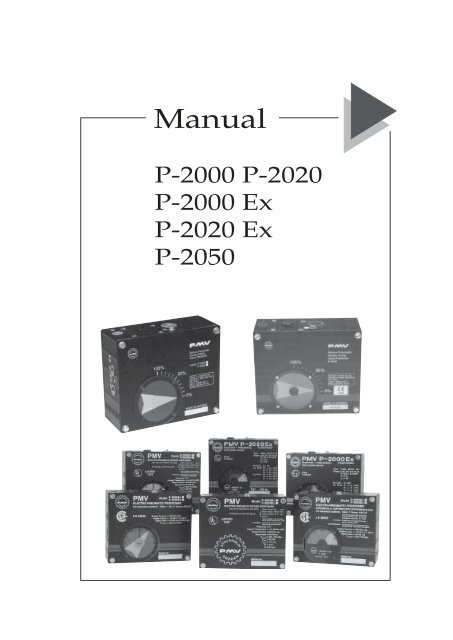
P2000 IOM EN - PMV Positioners
P2000 IOM EN - PMV Positioners
P2000 IOM EN - PMV Positioners

You also want an ePaper? Increase the reach of your titles
YUMPU automatically turns print PDFs into web optimized ePapers that Google loves.
<strong>PMV</strong> Positioner storage and handling procedures<strong>PMV</strong> <strong>Positioners</strong> are precision instruments which should be stored andhandled accordingly to avoid problems or damage.Appropriate precautions should be taken to protect units while in storage.Warehouse storageStored in original <strong>PMV</strong> shipping containers, units should be stored in anenvironmentally controlled area, i.e. clean, cool (15-26°C, 6-80°F) and dry, outof direct sunlight or weather exposure.Field storageNote: Once air supply to the positioner is connected and turned on, internalair bleed will prevent the ingress of moisture and protect the unit fromcorrosion. It is recommended that the air supply be left on at all times.• If units are installed immediately, tum, and leave on, the air supply.• If positioner must be stored outdoors, tighten all covers which mayloosened in shipment, make sure all open enclosure entry points are sealed.<strong>Positioners</strong> should be wrapped and sealed air and watertight with desiccantinside the plastic, units should be securely covered with an opaque cover andnot exposed to direct sunlight, rain or snow.Potential damage mechanismWhen units are stored in hot, humid climates, the daily heating/cooling cyclewill cause air to expand/ contract and be drawn in and out of the positionerhousing.Dependent on the local temperature variations, humidity, dew points and thetime in storage condensation could occur and accumulate inside causingerractic operation or failure due to water or corrosion. The potential forcondensation damage is especially high in southern climates and aggravatedif units are exposed to direct sunlight.For further assistance, please contact your nearest <strong>PMV</strong> office.– 4 –P-2000,2020,2050 and Ex-manual from <strong>PMV</strong> 13794-99.6
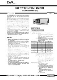
FunctionThe <strong>PMV</strong> E/P Positioner function is based on torquebalance. Direct current, 4-20 mA or 0-20 mA acting asinput signal creates, in the force coil (53) in the permanentmagnet (50) field, a force proportional to thesignal and, on the beam (92), a corresponding torqueThe position of the cylinder (C) piston is converted bymeans of the feedback linkage (L), cam (42), lower arm(21) and spring (40), to a force proportional to theposition of the cylinder (C) piston and, on the beam(92) a counter torque. When in balance, the cylinderposition equals the input signal value.The nozzle (114) without friction senses the balance ofthe beam (92). When, for example, the signal isincreased the torque corresponding to the signal onthe beam (92) will increase and the beam (92) will turnclock-wise. The nozzle (114) closes, and the nozzlepressure increases. The diaphragm assembly movesdownwards as does the spool (68) of the pilot valveactivated by the balancearm (57). Supply airflowsthrough connection C2 andairfrom the ”minus”chamberofthe cylinder(L) is exhausted throughconnection C1.Differential pressure is created in the cylinder, and thepiston will travel ”plus” until the torque change onthe beam (92), created by the piston position change,rebalances the beam (92) positionand the nozzlepressure. The diaphragm assembly will return toequilibrium position with the balance arm (57) guidingthe spool (68) to mid position. The piston of thecylinder (C) will stop in the position corresponding tothe new input signal.A change in position ofthe balance arm (57) creates,through the spring (93), anegative feedback torque onthe beam (92). Stable operationis thus achievedin spiteof possible great static amplification or sensitivity.The position of the spring (93) can be changed alongthe beam (92) and the balance arm (57) in order toadjust positioner gain, and thus the dynamics of thepositioner. The positioner can be adjusted to matchany small or large actuator.The lower arm (21) has a mechanism for zeroadjustments. The beam (92) has the mechanism foradjusting the range. To reverse the positioner actionthe cam (42) is flipped over and the pipe cormectionsC1 and C2 are interchanged.Split range is available by choosing the right curve onthe cam (42). Non-linear function is achieved byreshaping the cam (42). Such cams are available from<strong>PMV</strong>.The <strong>PMV</strong> E/P Positioner can also be used as a singleacting positioner by simply plugging one of theports C1 or C2.– 5 –P-2000,2020,2050 and Ex-manual from <strong>PMV</strong> 13794-99.6
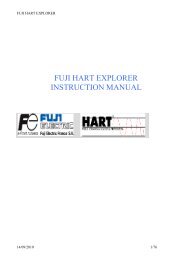
Air preparationThe <strong>PMV</strong> ELECTRO-PNEUMATIC Positionercan work with supply pressure up to 8 bar ( 120Psi”). In order to obtain a satisfactory operationand high reliability a filter (25 microns) shouldbe placed as close to the Positioner as possible.For larger pressure variations of the supply air(or the supply pressure is too high) a pressureregulator should be mounted next to the filter inorder to eliminate the fluctuations. The supplyair must be dry, clean and free from oil.Port I is to be used for the electrical connectiongland. This connection is 1/2~ NPT or PG 13.5(M- 20) internal thread.Input signal: 4-20 mA; 0-20 mAInput resistance: 240 Ohm±10%InstallationThe <strong>PMV</strong> E/P Positioner is available with a largeselection of feed back spindle designs to simplifythe mounting on the actuator.Ports C I and C2 are to be connected to theactuator.Port S is to be connected to the air supply (max 8bar or 120 psi3 which should be of instrumentquality (clean, dry and oil free). If your supplypressure is too high and/or the supply pressurechanges from time to time you must use a pressureregulator.Important noticeP-2000 Ex/P-2020 Ex should be connected tointrinsically safe circuits only. See installationdwg for further details.The <strong>PMV</strong> Positioner with the cover (33) and the side frame(3) dismounted.– 6 –P-2000,2020,2050 and Ex-manual from <strong>PMV</strong> 13794-99.6
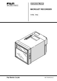
1. CalibrationPLEASE NOTICE: For easyacsess to important partsplease back off the fourscrews. Remove the cover.Fig 1The side frame can be removedby simply pressing outone end of the frame from theslot in the main frame.Fig 2NOTE: P-2000 series positionerare factory calibrated to4-20 mA input signal. Startby adjusting zero first, thenstroke the unit and checkreading before furtheradjustments.1.1 Cam settingAfter mounting the <strong>PMV</strong>Positioner on your actuatorand before switching on thesupply air, if possible,manually operate theactuator from fully open tofully closed position andcheck that the cam iscorrectly oriented. Makeadjustments if neccessary(see instructions below).Figure 1Figure 2Position the cam as shown.The ball bearing should notride on the inactive portion ofthe cam. Tighten the nut.Fig 4NOTE: The cam will turnslightly with the nut as it istightened. Be sure to allow forthis slight clockwise rotation.1.2 To change the actionTo change the action, the cammust be flipped over and thetubes to the connections C1and C2 must change places.Fig 51.3 Gain adjustmentPLEASE NOTE: Beforeadjusting the gain pleaseswitch of the supply pressure.The gain surpression springcan be moved along the beamand the balance arm. The feedbackstiffness can thus beadjusted so that the <strong>PMV</strong> Positionerdynanics matches theactuator size.Fig 6&7You will find a number ofpositioning holes in the beamand the balance arm for thespring. The smaller theactuator the lower is the acceptablelevel of the gain.Figure 4Figure 5Should manual operation ofthe actuator not be possiblewe recommend you to backoff the nut holding the cam.Fig 3High gainAdjust the position of the camso that the ball bearing on thelower arm rests on the lowestpart on the correct curve ofthe cam. You have three differentcurves to choose from onthe standard cam (0-100, 0-50or 50-100 % of the control signalfor the full stroke of theactuator).Figure 3Low gainFigure 6Figure 7– 7 –P-2000,2020,2050 and Ex-manual from <strong>PMV</strong> 13794-99.6
1.3.1 To reduce the gain2. MaintenanceMove the spring to the left.Please use a pair of tweezerswhen moving the spring.Fig 8Changing the position of thespring effects the zeroadjustment and new zeroadjustment is neccessary (see1.4 below).1.4 Zero adjustmentSet the input signal at 4 mA(or 0 mA for 0-20 mA controlrange) and switch on the airsupply.When turning the zero settingscrew to the right theactuator will move in thedirection of the decreasing signal.Adjust the screw until theactuator is in the ”starting”position.Fig 91.5 Range adjustmentSet the input signal at its finalvalue e.g. 20 mA.If the turning angle of theactuator is too large (small) adownwards (upwards) rotationof the range adjustmentscrew will reduce (increase)the actuator travel.Fig 10Figure 8Figure 9Figure 10The permanent magnet has avery strong magnetic field andin order to avoid iron dustentering into the narrow gapfor the force coil you shouldnever leave the <strong>PMV</strong> E/P Positionerwithout the covermounted.Regular maintenance of the<strong>PMV</strong> E/P Positioner is notrequired. The need formaintenance is depending onyour supply air quality.Should iron dust enter intothe magnet, restricting the freemovement of the force coil ,this would cause disturbances.2.1 The restriction plugClose to the connection (S)for the supply air you willfind the restriction plugwhich is easily removablefor exchange. Beforereplacing the restrictor plugplease check that the Oringsare in good condition.Fig 122.2 To clean the vahe bodyUnscrew the four screws andand remove the cover.Fig 13Figure 12The range and zeroadjustments has a smalleffect on one and other.Therefore a few zero andrange adjustments might beneeded in turns.PLEASE NOTICE: Should tbezero adjustment reach the limityou might be helped byusing the other springmounting on the spring guide.Use a pair of tweezers tochange the position of thespring.Fig 11Figure 11Remove the side frame.Fig 14Figure 13Figure 14– 8 –P-2000,2020,2050 and Ex-manual from <strong>PMV</strong> 13794-99.6
Carefully lift out the E/Pconverter.Fig 23The middle section can nowbe separated from the body.Fig 26Figure 23Figure 26Remove the gain supressionspring by using a pair oftweezers.Fig 24Figure 24Pull the diaphragm-pistonassembly upwards apart fromthe middle section.Fig 27Figure 27Loosen the screw and be carefulto use a holding-up toolfor the retainer to avoid tensionon the diaphragms.Fig 25Figure 25Replace the broken diaphragm and assembly thepositioner step by step following the opposite orderin which you now have disassembled it.Be sure to check that all O-rings are in good conditionand in the proper places.– 10 –P-2000,2020,2050 and Ex-manual from <strong>PMV</strong> 13794-99.6
Trouble ShootingSignal change has no effect on the actuator position.– Make sure the supply pressure is switched on.– Signal wires are wrongly connected.– The wiring between the terminal block and the printed circuit board onthe force coil is broken. Check resistance.– Pipe connections between the <strong>PMV</strong> Positioner and the actuator is wrong.– A wrong portion of the cam is being used.With a small change in the control signal the actuator runs to the endposition.– Pipe connections between the <strong>PMV</strong> Positioner and the actuator is wrong.Inaccurate positiomng– Dirty valve body.– Dirty restrictor or nozzle.– Iron dust in the magnet gap.– Defective diaphragms.– The sizing of the actuator is incorrect. Output torque of the actuator is toosmall or the supply pressure is too low.– Torque requirement of the valve has increased.Overshoot or hunting during positioning.– Internal gain is too high.– Capacity of the supply pipe is too small or air filter is clogged. In this eventthe input pressure to the <strong>PMV</strong> Positioner drops steeply when the pilot valvefeeds air into the actuator.– 11 –P-2000,2020,2050 and Ex-manual from <strong>PMV</strong> 13794-99.6
P-2000,2020,2050 and Ex-manual from <strong>PMV</strong> 13794-99.6– 12 –
P-2000,2020,2050 and Ex-manual from <strong>PMV</strong> 13794-99.6– 13 –
Exploded drawing– 14 –P-2000,2020,2050 and Ex-manual from <strong>PMV</strong> 13794-99.6
Dimensional drawing– 15 –P-2000,2020,2050 and Ex-manual from <strong>PMV</strong> 13794-99.6
SUBSIDIARIES:Coulton Instrumentation Ltd17 Somerford Business ParkBH23 3RU Christchurch<strong>EN</strong>GLANDTel: +44 1202 480 303Fax: +44 1202 480 808E-mail: sales@coulton.com<strong>PMV</strong>-USA, Inc1440 Lake Front CircleUnit 160The Woodlands, Texas 77380USATel: +1 281 292 7500Fax: +1 281 292 7760E-mail: pmvusa@pmvusa.comInternet: www.pmvusa.comPalmstiernas Instrument ABTulegatan 15SE-113 53 StockholmSWED<strong>EN</strong>Tel: +46 (0) 8 15 14 85Fax: +46 (0) 8 673 39 83E-mail: info@pmvpositioners.comInternet: www.pmvpositioners.com<strong>PMV</strong> Regeltechnik GmbHLosensteinleiten 7A-4493 WolfernAUSTRIATel: +43 (0) 7253 82410Fax: +43 (0) 7253 82419E-mail: aw.pmv@ambos.co.at<strong>PMV</strong> GmbHPostfach 2310D-41554 KaarstGERMANYTel: +49 (0) 2131 667 081/82Fax: +49 (0) 2131 667 083Palmstiernas Svenska ABBox 21SE-663 21 SkoghallSWED<strong>EN</strong>Tel: +46 (0) 54 52 14 70Fax: +46 (0) 54 52 14 42E-mail: info@palmstiernas.seInternet: www.palmstiernas.se(The information in this brochure is subject to change without notice.)13794/99.6 EkvatorDistributor– 16 –P-2000,2020,2050 and Ex-manual from <strong>PMV</strong> 13794-99.6