PXR3 Instruction Manual - Coulton Instrumentation
PXR3 Instruction Manual - Coulton Instrumentation
PXR3 Instruction Manual - Coulton Instrumentation

Create successful ePaper yourself
Turn your PDF publications into a flip-book with our unique Google optimized e-Paper software.
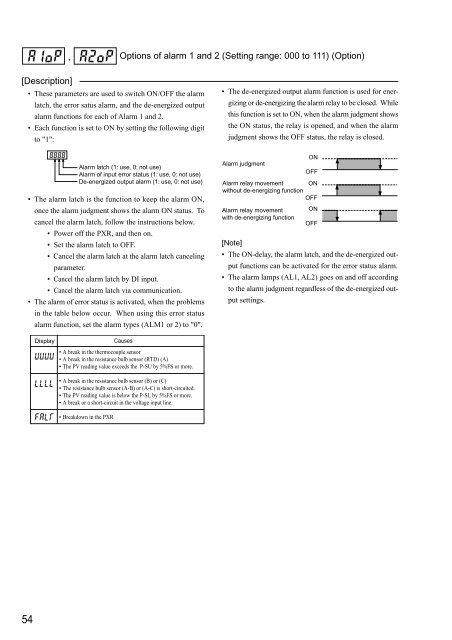
, Options of alarm 1 and 2 (Setting range: 000 to 111) (Option)[Description]• These parameters are used to switch ON/OFF the alarmlatch, the error satus alarm, and the de-energized outputalarm functions for each of Alarm 1 and 2.• Each function is set to ON by setting the following digitto "1":• The de-energized output alarm function is used for energizingor de-energizing the alarm relay to be closed. Whilethis function is set to ON, when the alarm judgment showsthe ON status, the relay is opened, and when the alarmjudgment shows the OFF status, the relay is closed.Alarm latch (1: use, 0: not use)Alarm of input error status (1: use, 0: not use)De-energized output alarm (1: use, 0: not use)• The alarm latch is the function to keep the alarm ON,once the alarm judgment shows the alarm ON status. Tocancel the alarm latch, follow the instructions below.• Power off the PXR, and then on.• Set the alarm latch to OFF.• Cancel the alarm latch at the alarm latch cancelingparameter.• Cancel the alarm latch by DI input.• Cancel the alarm latch via communication.• The alarm of error status is activated, when the problemsin the table below occur. When using this error statusalarm function, set the alarm types (ALM1 or 2) to "0".Alarm judgmentAlarm relay movementwithout de-energizing functionAlarm relay movementwith de-energizing functionONOFFONOFFONOFF[Note]• The ON-delay, the alarm latch, and the de-energized outputfunctions can be activated for the error status alarm.• The alarm lamps (AL1, AL2) goes on and off accordingto the alarm judgment regardless of the de-energized outputsettings.DisplayCauses• A break in the thermocouple sensor• A break in the resistance bulb sensor (RTD) (A)• The PV reading value exceeds the P-SU by 5%FS or more.• A break in the resistance bulb sensor (B) or (C)• The resistance bulb sensor (A-B) or (A-C) is short-circuited.• The PV reading value is below the P-SL by 5%FS or more.• A break or a short-circuit in the voltage input line.• Breakdown in the PXR54