PXR3 Instruction Manual - Coulton Instrumentation
PXR3 Instruction Manual - Coulton Instrumentation
PXR3 Instruction Manual - Coulton Instrumentation

You also want an ePaper? Increase the reach of your titles
YUMPU automatically turns print PDFs into web optimized ePapers that Google loves.
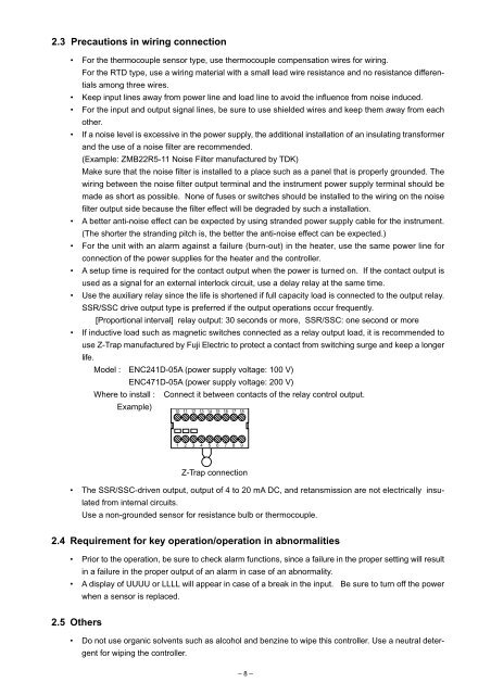
2.3 Precautions in wiring connection• For the thermocouple sensor type, use thermocouple compensation wires for wiring.For the RTD type, use a wiring material with a small lead wire resistance and no resistance differentialsamong three wires.• Keep input lines away from power line and load line to avoid the influence from noise induced.• For the input and output signal lines, be sure to use shielded wires and keep them away from eachother.• If a noise level is excessive in the power supply, the additional installation of an insulating transformerand the use of a noise filter are recommended.(Example: ZMB22R5-11 Noise Filter manufactured by TDK)Make sure that the noise filter is installed to a place such as a panel that is properly grounded. Thewiring between the noise filter output terminal and the instrument power supply terminal should bemade as short as possible. None of fuses or switches should be installed to the wiring on the noisefilter output side because the filter effect will be degraded by such a installation.• A better anti-noise effect can be expected by using stranded power supply cable for the instrument.(The shorter the stranding pitch is, the better the anti-noise effect can be expected.)• For the unit with an alarm against a failure (burn-out) in the heater, use the same power line forconnection of the power supplies for the heater and the controller.• A setup time is required for the contact output when the power is turned on. If the contact output isused as a signal for an external interlock circuit, use a delay relay at the same time.• Use the auxiliary relay since the life is shortened if full capacity load is connected to the output relay.SSR/SSC drive output type is preferred if the output operations occur frequently.[Proportional interval] relay output: 30 seconds or more, SSR/SSC: one second or more• If inductive load such as magnetic switches connected as a relay output load, it is recommended touse Z-Trap manufactured by Fuji Electric to protect a contact from switching surge and keep a longerlife.Model : ENC241D-05A (power supply voltage: 100 V)ENC471D-05A (power supply voltage: 200 V)Where to install : Connect it between contacts of the relay control output.Example)10 11 12 13 14 15 16 17 181 2 3 4 5 6 7 8 9Z-Trap connection• The SSR/SSC-driven output, output of 4 to 20 mA DC, and retansmission are not electrically insulatedfrom internal circuits.Use a non-grounded sensor for resistance bulb or thermocouple.2.4 Requirement for key operation/operation in abnormalities• Prior to the operation, be sure to check alarm functions, since a failure in the proper setting will resultin a failure in the proper output of an alarm in case of an abnormality.• A display of UUUU or LLLL will appear in case of a break in the input. Be sure to turn off the powerwhen a sensor is replaced.2.5 Others• Do not use organic solvents such as alcohol and benzine to wipe this controller. Use a neutral detergentfor wiping the controller.– 8 –