TOPS Pro User Guide for v6.X - TOPS - Packaging Software
TOPS Pro User Guide for v6.X - TOPS - Packaging Software
TOPS Pro User Guide for v6.X - TOPS - Packaging Software

You also want an ePaper? Increase the reach of your titles
YUMPU automatically turns print PDFs into web optimized ePapers that Google loves.
<strong>TOPS</strong> ®<br />
<strong>Pro</strong> <strong>User</strong> <strong>Guide</strong><br />
(Version 6.X)<br />
March 2010 Print Version<br />
Total Optimization <strong>Packaging</strong> <strong>Software</strong><br />
<strong>TOPS</strong> <strong>Software</strong> Corporation<br />
www.topseng.com<br />
275 W. Campbell Road, Suite 600 info@topseng.com<br />
Richardson, Texas 75080 USA<br />
tech@topseng.com<br />
(972) 739-8677 Telephone sales@topseng.com<br />
(972) 739-9478 Fax mvp@topseng.com
Copyright © 1996-2010 <strong>TOPS</strong> ® <strong>Software</strong> Corporation. All rights reserved.<br />
The software described in this document is furnished under a license agreement. The<br />
software may be used or copied only in accordance with the terms of the agreement. No<br />
part of this document may be reproduced or transmitted in any <strong>for</strong>m or by any means,<br />
electronic or mechanical, including photocopying and recording, <strong>for</strong> any purpose without<br />
the express written permission of <strong>TOPS</strong> <strong>Software</strong> Corporation.<br />
In<strong>for</strong>mation in this document is subject to change without notice and does not represent<br />
product specification or commitment on the part of <strong>TOPS</strong> <strong>Software</strong> Corporation.<br />
Windows is a trademark of Microsoft Corporation.<br />
Microsoft Word is a trademark of Microsoft Corporation.<br />
Microsoft Excel is a trademark of Microsoft Corporation.<br />
Microsoft Power Point is a trademark of Microsoft Corporation.<br />
<strong>TOPS</strong> ® is a registered trademark of <strong>TOPS</strong> <strong>Software</strong> Corporation.<br />
MAXLOAD ® is a registered trademark of <strong>TOPS</strong> <strong>Software</strong> Corporation.<br />
MIXLOAD ® is a registered trademark of <strong>TOPS</strong> <strong>Software</strong> Corporation.<br />
Adobe Acrobat © is a registered trademark of Adobe Systems Incorporated.<br />
<strong>TOPS</strong> <strong>Software</strong> Corporation<br />
275 W. Campbell Road, Suite 600<br />
Richardson, Texas 75080 USA<br />
Telephone: (972) 739-8677<br />
Facsimile: (972) 739-9478<br />
In<strong>for</strong>mation: info@topseng.com<br />
Technical Support: tech@topseng.com<br />
Sales:<br />
sales@topseng.com<br />
MVP<br />
mvp@topseng.com<br />
Web Site:<br />
www.topseng.com
Table of Contents<br />
Preface.......................................................................................................xv<br />
About <strong>TOPS</strong> <strong>Pro</strong> ........................................................................................xv<br />
How the <strong>User</strong> <strong>Guide</strong> is Organized ........................................................... xvi<br />
New Features in <strong>TOPS</strong> <strong>Pro</strong> (V6.X).......................................................... xix<br />
Chronology of Features in <strong>TOPS</strong> <strong>Pro</strong> ........................................................xx<br />
Chapter 1: Getting Started ................................................................... 1-1<br />
Introduction.............................................................................................. 1-1<br />
System Requirements/Specifications....................................................... 1-1<br />
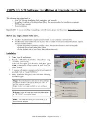
Installing <strong>TOPS</strong> <strong>Pro</strong> ................................................................................. 1-2<br />
Starting & Setting Up <strong>TOPS</strong> <strong>Pro</strong> ............................................................. 1-7<br />
Upgrading <strong>TOPS</strong> <strong>Pro</strong> ............................................................................... 1-8<br />
<strong>TOPS</strong> <strong>Pro</strong> <strong>Pro</strong>gram Group ..................................................................... 1-10<br />
Uninstall and Move <strong>TOPS</strong> <strong>Pro</strong> .............................................................. 1-11<br />
Contact In<strong>for</strong>mation............................................................................... 1-12<br />
Chapter 2: The Basics............................................................................ 2-1<br />
Introduction.............................................................................................. 2-1<br />
Control Panel ........................................................................................... 2-2<br />
Menu Bar ........................................................................................... 2-3<br />
Windows Toolbar............................................................................... 2-4<br />
Template Toolbar............................................................................... 2-6<br />
Button-Style Menus ........................................................................... 2-6<br />
Package Design Sequence ................................................................. 2-8<br />
Shortcut Buttons ................................................................................ 2-9<br />
Per<strong>for</strong>m a Simple Analysis .................................................................... 2-10<br />
Define the Package Design Sequence.............................................. 2-10<br />
Save the Package Design Sequence as a Template.......................... 2-10<br />
Define Shipcase and Pallet Parameters............................................ 2-12<br />
Revise Parameters <strong>for</strong> an Analysis (if necessary)............................ 2-14<br />
Analysis View........................................................................................ 2-15<br />
Solution View Pane ......................................................................... 2-16<br />
Solution View Menu........................................................................ 2-18<br />
Statistics View Pane......................................................................... 2-20<br />
Solution List Pane............................................................................ 2-21<br />
Solution List - Tab View ................................................................. 2-23<br />
Display Thumbnail View of Pallet Patterns .................................... 2-24<br />
Layer Parameters ................................................................................... 2-25<br />
Unitload Drawing Options............................................................... 2-26<br />
Function Buttons.............................................................................. 2-27<br />
Table of Contents<br />
i
Filler................................................................................................. 2-28<br />
Spread .............................................................................................. 2-28<br />
Rotate ............................................................................................... 2-29<br />
Print the Analysis................................................................................... 2-30<br />
Define Print Parameters ................................................................... 2-30<br />
Add Text, Lines or Images to Printed Output.................................. 2-34<br />
Change the Company Logo in Printed Output................................. 2-36<br />
Change the Printer Pen Width ......................................................... 2-36<br />
Copy <strong>TOPS</strong> Graphics to Other <strong>Pro</strong>grams .............................................. 2-37<br />
Copy a Single Graphic..................................................................... 2-37<br />
Copy the Entire Print Preview ......................................................... 2-38<br />
Copy a Graphic to Microsoft Word ................................................. 2-38<br />
Copy a Graphic to Microsoft Power Point....................................... 2-39<br />
Paste Special .................................................................................... 2-40<br />
Save the Analysis................................................................................... 2-41<br />
Direct Email From <strong>TOPS</strong> <strong>Pro</strong>................................................................ 2-42<br />
Email Analyses as Graphics Reports ............................................... 2-42<br />
Email Analyses as Text Files........................................................... 2-43<br />
Email Stacking Strength Results...................................................... 2-43<br />
Direct Export to PDF ............................................................................. 2-43<br />
Chapter 3: Advanced Features.............................................................3-1<br />
Introduction.............................................................................................. 3-1<br />
Exercise #1: Fixed Carton-New Shipcase-Pallet Analysis..................... 3-3<br />
Exercise #2: New Carton-New Shipcase-Pallet...................................... 3-9<br />
Exercise #3: Shipcase Consolidation Analysis (Database Function) ... 3-14<br />
Exercise #4: Knockdown Analysis ....................................................... 3-18<br />
Paste-On Graphics ................................................................................. 3-25<br />
Export............................................................................................... 3-29<br />
Export a Graphic.............................................................................. 3-29<br />
Export a <strong>Pro</strong>duct Report .................................................................. 3-31<br />
Export a Case ................................................................................... 3-32<br />
Export a Carton................................................................................ 3-33<br />
Export an Analysis........................................................................... 3-34<br />
Export to a Robotic Palletizer.......................................................... 3-35<br />
Artios Integration................................................................................... 3-37<br />
Quick Print Template System ................................................................ 3-37<br />
Combined Report................................................................................... 3-37<br />
Control of Displayed Statistics .............................................................. 3-37<br />
Shipcase Database Option ..................................................................... 3-38<br />
Send to Word Function .......................................................................... 3-40<br />
Create a Custom Word Template..................................................... 3-40<br />
Tips on Creating Word Templates................................................... 3-44<br />
Export Analysis to Word ................................................................. 3-44<br />
ii<br />
<strong>TOPS</strong> <strong>Pro</strong> (Version 6.X) <strong>User</strong> <strong>Guide</strong>
Chapter 4: Publishing an Analysis ......................................................4-1<br />
Introduction..............................................................................................4-1<br />
Viewing the Published Analyses ............................................................. 4-4<br />
Chapter 5: Pallet and Shipcase Pattern Editor...................................5-1<br />
Introduction.............................................................................................. 5-1<br />
Using the Pallet Pattern Editor................................................................. 5-1<br />
Move Boxes on the Pattern................................................................ 5-6<br />
Select Multiple Boxes........................................................................ 5-6<br />
Rubber-Banding................................................................................. 5-6<br />
Align Left/Right/Up/Down Buttons .................................................. 5-7<br />
Spread Horizontal/Vertical Buttons................................................... 5-8<br />
Center Horizontal/Vertical Buttons ................................................... 5-9<br />
Flush Up/Down/Left/Right Buttons................................................... 5-9<br />
Remove Boxes from the Pattern ...................................................... 5-11<br />
Add New Boxes to the Pattern......................................................... 5-11<br />
Add a Box Using the Horizontal/Vertical Option ........................... 5-12<br />
Using the Interactive Shipcase Sizing Editor ........................................ 5-13<br />
Move Cartons Inside the Shipcase................................................... 5-16<br />
Rotate the Cartons............................................................................ 5-16<br />
Add a New Carton ........................................................................... 5-16<br />
Resize the Shipcase.......................................................................... 5-17<br />
Chapter 6: Mix<strong>Pro</strong> Pallet .....................................................................6-1<br />
Introduction..............................................................................................6-1<br />
Mix<strong>Pro</strong> Pallet Editor ................................................................................6-1<br />
Create a Mixed Pallet Manually ..............................................................6-3<br />
Create a Mixed Pallet Using Layers ........................................................6-9<br />
Layer Manipulations ........................................................................6-12<br />
Mix<strong>Pro</strong> Auto Load Generator ................................................................6-13<br />
Direct Email From Mix<strong>Pro</strong> Pallet..........................................................6-16<br />
Tips <strong>for</strong> Working with Cases on a Pallet ...............................................6-17<br />
Chapter 7: Mix<strong>Pro</strong> Tray ....................................................................... 7-1<br />
Introduction.............................................................................................. 7-1<br />
Mix<strong>Pro</strong> Tray Editor.................................................................................. 7-1<br />
Create a New Shipcase/Tray.............................................................. 7-3<br />
Create A New Package ...................................................................... 7-5<br />
Add Packages to the Shipcase/Tray................................................... 7-7<br />
Save the Mixed Tray.......................................................................... 7-9<br />
Use the Mixed Tray in Mixed Pallet.................................................. 7-9<br />
Direct Email From Mix<strong>Pro</strong> Tray............................................................ 7-12<br />
Tips <strong>for</strong> Working with Packages on a Tray ........................................... 7-13<br />
Table of Contents<br />
iii
Chapter 8: Create A Shape Yourself (CASY).....................................8-1<br />
Introduction.............................................................................................. 8-1<br />
CASY Primary Package........................................................................... 8-1<br />
Other Primary Package Shape Functions......................................... 8-10<br />
CASY Shipcase/Tray............................................................................. 8-11<br />
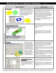
Chapter 9: Stacking Strength ...............................................................9-1<br />
Introduction.............................................................................................. 9-1<br />
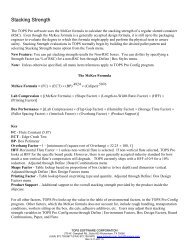
The McKee Formula................................................................................ 9-1<br />
Edge Crush Test....................................................................................... 9-3<br />
Ring Crush Test ....................................................................................... 9-3<br />
Calculate Stacking Strength..................................................................... 9-4<br />
Environment Factors Dialog Box ...................................................... 9-7<br />
Stacking Strength Results ........................................................................ 9-8<br />
Stacking Strength Results – Menu Options ........................................... 9-12<br />
Sort Menu ........................................................................................ 9-12<br />
Tools Menu ...................................................................................... 9-13<br />
Email Stacking Strength Combo Board List.................................... 9-13<br />
Define Stacking Strength Factor <strong>for</strong> a Non-RSC Box........................... 9-14<br />
Configuration Default Settings .............................................................. 9-15<br />
Chapter 10: Package <strong>Pro</strong>file ...............................................................10-1<br />
Introduction............................................................................................ 10-1<br />
Create a Package <strong>Pro</strong>file ........................................................................ 10-1<br />
Add a <strong>Pro</strong>duct to the Package <strong>Pro</strong>file .................................................... 10-4<br />
Edit a <strong>Pro</strong>duct in the Package <strong>Pro</strong>file .................................................... 10-8<br />
Remove a <strong>Pro</strong>duct from the Package <strong>Pro</strong>file ......................................... 10-9<br />
Chapter 11: Printing............................................................................11-1<br />
Introduction............................................................................................ 11-1<br />
Print Preview – Analysis........................................................................ 11-1<br />
Define Print Parameters ................................................................... 11-3<br />
Print Preview – Package <strong>Pro</strong>file ............................................................ 11-7<br />
Annotate a Printout with Text................................................................ 11-9<br />
Insert Arrows or Lines on a Printout ................................................... 11-11<br />
Annotate a Printout with Graphics....................................................... 11-14<br />
Tips <strong>for</strong> Working with Graphics.................................................... 11-15<br />
Edit a Graphic Image in Print Preview ................................................ 11-16<br />
Quick Print........................................................................................... 11-17<br />
Combined Report: Compare Solution.................................................. 11-18<br />
Combined Report: Compare Analysis ................................................. 11-22<br />
Combined Report <strong>for</strong> Knocked-Down and Erected Boxes............ 11-24<br />
Printer Width........................................................................................ 11-25<br />
iv<br />
<strong>TOPS</strong> <strong>Pro</strong> (Version 6.X) <strong>User</strong> <strong>Guide</strong>
Chapter 12: Designing Box Styles ......................................................12-1<br />
Introduction............................................................................................ 12-1<br />
General <strong>Guide</strong>lines ................................................................................ 12-2<br />
Box Style Drawing Parameters.............................................................. 12-4<br />
Common Footprint Standard............................................................ 12-5<br />
Display Case .................................................................................... 12-5<br />
Display Tray .................................................................................... 12-6<br />
HSC.................................................................................................. 12-6<br />
HSC with Top .................................................................................. 12-7<br />
RSC.................................................................................................. 12-7<br />
Shrinkwrap....................................................................................... 12-8<br />
Shroud.............................................................................................. 12-8<br />
Solid ................................................................................................. 12-9<br />
Strap Bundle .................................................................................... 12-9<br />
Tear Out ......................................................................................... 12-10<br />
Tray................................................................................................ 12-10<br />
Tray/HSC ....................................................................................... 12-11<br />
Tuck ............................................................................................... 12-11<br />
Wrap Around ................................................................................. 12-12<br />
Chapter 13: Designing Divider Styles ................................................ 13-1<br />
Introduction............................................................................................ 13-1<br />
General <strong>Guide</strong>lines ................................................................................ 13-2<br />
2-Way Divider ................................................................................. 13-3<br />
2-Way Air Cell................................................................................. 13-4<br />
U Over.............................................................................................. 13-5<br />
U Partition........................................................................................ 13-6<br />
U Simple .......................................................................................... 13-7<br />
Z Partition ........................................................................................ 13-8<br />
Zig Zag............................................................................................. 13-9<br />
Other Partitions .............................................................................. 13-10<br />
Chapter 14: Configuration..................................................................14-1<br />
Introduction............................................................................................ 14-1<br />
File Menu............................................................................................... 14-2<br />
<strong>User</strong> Login ....................................................................................... 14-2<br />
<strong>User</strong> List........................................................................................... 14-2<br />
Import............................................................................................... 14-2<br />
Export............................................................................................... 14-3<br />
Exit................................................................................................... 14-3<br />
Define Menu .......................................................................................... 14-4<br />
Configuration ................................................................................... 14-4<br />
Language.......................................................................................... 14-4<br />
Defaults............................................................................................ 14-5<br />
Environment Factors........................................................................ 14-5<br />
Table of Contents<br />
v
Box Design Factors.......................................................................... 14-6<br />
Board Combinations ........................................................................ 14-6<br />
Paper ................................................................................................ 14-6<br />
Flutes................................................................................................ 14-6<br />
Supervisor Menu.................................................................................... 14-7<br />
Login/Logout ................................................................................... 14-7<br />
Global Configuration ....................................................................... 14-7<br />
Rebuild Files .................................................................................... 14-7<br />
Chapter 15: Supervisor Functions .....................................................15-1<br />
Introduction............................................................................................ 15-1<br />
Login/Logout ......................................................................................... 15-2<br />
Change Password................................................................................... 15-3<br />
Logoff a <strong>User</strong> ......................................................................................... 15-4<br />
Add a <strong>User</strong> to the System....................................................................... 15-5<br />
Delete a <strong>User</strong> from the System .............................................................. 15-6<br />
Rename a <strong>User</strong> in the System ................................................................ 15-6<br />
Approve an Analysis.............................................................................. 15-7<br />
Deny Approval of an Analysis............................................................... 15-8<br />
Set Up a Quick Print Template .............................................................. 15-9<br />
Global Configuration ........................................................................... 15-10<br />
Rebuild Files ........................................................................................ 15-11<br />
Set Up Statistics ................................................................................... 15-11<br />
Open and Transfer Other <strong>User</strong>s' Analyses........................................... 15-13<br />
Chapter 16: RFID Analysis................................................................16-1<br />
Introduction............................................................................................16-1<br />
Sort by RFID..........................................................................................16-2<br />
RFID Analysis .......................................................................................16-4<br />
Chapter 17: Eco Savings Report ........................................................17-1<br />
Introduction............................................................................................17-1<br />
Create the Analysis ................................................................................17-1<br />
Set up Cost Factors ................................................................................17-1<br />
Select the Solutions................................................................................17-3<br />
Chapter 18: Send to MS Office...........................................................18-1<br />
Introduction............................................................................................18-1<br />
MS Office Templates.............................................................................18-1<br />
Export to MS Word................................................................................18-2<br />
Export to MS Excel................................................................................18-4<br />
Create a Custom Word Template...........................................................18-5<br />
Copy Blank.dot to MyTemplate.dot ................................................18-5<br />
Format the Template........................................................................18-6<br />
Add Tops Bookmarks ......................................................................18-8<br />
vi<br />
<strong>TOPS</strong> <strong>Pro</strong> (Version 6.X) <strong>User</strong> <strong>Guide</strong>
Tips on Using Bookmarks in MS Word ........................................18-13<br />
Create a Custom Excel Template.........................................................18-14<br />
Create & Format a New Worksheet in Excel Template ................18-14<br />
Assign New Cell References .........................................................18-16<br />
Tips on Using <strong>TOPS</strong> Templates in MS Excel ...............................18-20<br />
Appendix A: Frequently Asked Questions ........................................ A-1<br />
Appendix B: Dialog Boxes....................................................................B-1<br />
Introduction..............................................................................................B-1<br />
Common Features ....................................................................................B-1<br />
Graphic Online Display (g.o.d.) Feature............................................B-1<br />
Bulge Factor.......................................................................................B-2<br />
Printing Bulge Data ...........................................................................B-3<br />
Additional Costing Data ..........................................................................B-4<br />
(Analysis) Save As...................................................................................B-5<br />
Analysis Search........................................................................................B-7<br />
Assign Graphics.......................................................................................B-9<br />
Bag Options ...........................................................................................B-10<br />
Headspace ........................................................................................B-10<br />
Bag Parameters ......................................................................................B-12<br />
Primary Pack vs. Shipcase Bag Parameters.....................................B-13<br />
Bags Shaped Like Cartons...............................................................B-13<br />
Blister Pack Options ..............................................................................B-16<br />
Blister Pack Parameters .........................................................................B-17<br />
Board Combinations ..............................................................................B-19<br />
Bottle Options ........................................................................................B-21<br />
Bottle Parameters...................................................................................B-22<br />
Box Design Factors................................................................................B-25<br />
Bucket Options ......................................................................................B-27<br />
Bucket Parameters .................................................................................B-28<br />
Bundle Parameters .................................................................................B-31<br />
Calculate MixPal....................................................................................B-33<br />
Can Options ...........................................................................................B-34<br />
Can Parameters ......................................................................................B-35<br />
Designing Soda Cans .......................................................................B-35<br />
Carton Options.......................................................................................B-37<br />
Headspace ........................................................................................B-37<br />
Carton Parameters..................................................................................B-39<br />
Case Styles.............................................................................................B-42<br />
Color Selection ......................................................................................B-46<br />
Combined Report Parameters ................................................................B-47<br />
Configuration .........................................................................................B-48<br />
Configuration (Global) ..........................................................................B-52<br />
Container Diagram List .........................................................................B-55<br />
Container Diagram Spec........................................................................B-56<br />
Table of Contents<br />
vii
Container Pattern ...................................................................................B-58<br />
Costing Data ..........................................................................................B-59<br />
Decimals ................................................................................................B-61<br />
Defaults (Button Menu Styles) ..............................................................B-62<br />
Defaults (Carton/Bag Sizing).................................................................B-64<br />
Defaults (Intermediate Pack View)........................................................B-65<br />
Defaults (Intermediate Sizing)...............................................................B-66<br />
Defaults (Pallet) .....................................................................................B-68<br />
Defaults (Pallet Spec) ............................................................................B-69<br />
Defaults (Primary Package) ...................................................................B-70<br />
Defaults (Print) ......................................................................................B-71<br />
Defaults (Shipcase) ................................................................................B-73<br />
Defaults (Shipcase Patterns) ..................................................................B-74<br />
Defaults (Shipcase Sizing).....................................................................B-75<br />
Defaults (Stack Strength).......................................................................B-77<br />
Defaults (Transit Vehicle Patterns)........................................................B-78<br />
Defaults (UnitLoad Patterns) .................................................................B-79<br />
Defaults (UnitLoad Sizing)....................................................................B-80<br />
Defaults (Vehicle Load Sizing) .............................................................B-82<br />
Define Bag .............................................................................................B-84<br />
Define Bottle..........................................................................................B-86<br />
Define Can / Drum.................................................................................B-88<br />
Define Carton.........................................................................................B-89<br />
Define Dividers......................................................................................B-90<br />
Define Film ............................................................................................B-93<br />
Define Flute ...........................................................................................B-94<br />
Define Milk Carton................................................................................B-96<br />
Define Package Info (Mix<strong>Pro</strong>)...............................................................B-97<br />
Define Pallet ..........................................................................................B-98<br />
Define Paper.........................................................................................B-102<br />
Define <strong>Pro</strong>duct .....................................................................................B-103<br />
Define Shipcase ...................................................................................B-105<br />
Define Shipping Case ..........................................................................B-106<br />
Define Tub ...........................................................................................B-108<br />
Define Vehicle .....................................................................................B-110<br />
Dividers................................................................................................B-111<br />
Drum Options.......................................................................................B-113<br />
Drum Parameters .................................................................................B-114<br />
Easy Import..........................................................................................B-115<br />
EcoSavings Report (ESR) - Analysis ..................................................B-117<br />
EcoSavings Report (ESR) - Configuration..........................................B-119<br />
Environment Factors............................................................................B-121<br />
Export Analysis....................................................................................B-123<br />
Export Robotic Palletizer.....................................................................B-125<br />
Export to ASCII ...................................................................................B-126<br />
Fractions...............................................................................................B-128<br />
viii<br />
<strong>TOPS</strong> <strong>Pro</strong> (Version 6.X) <strong>User</strong> <strong>Guide</strong>
Get Export File Name ..........................................................................B-129<br />
Import From Artios..............................................................................B-130<br />
Import From ASCII..............................................................................B-131<br />
Intermediate Pack Options...................................................................B-132<br />
Sizing .............................................................................................B-132<br />
Intermediate Pack Parameters..............................................................B-134<br />
Layer Parameters .................................................................................B-138<br />
Milk Carton Options ............................................................................B-141<br />
Headspace ......................................................................................B-141<br />
Milk Carton Parameters .......................................................................B-142<br />
New <strong>User</strong> .............................................................................................B-144<br />
Open Analysis......................................................................................B-145<br />
Open Archived Analysis......................................................................B-148<br />
Open Request <strong>for</strong> Approval .................................................................B-150<br />
Package <strong>Pro</strong>file ....................................................................................B-151<br />
Pallet Parameters (Mixp<strong>Pro</strong>)................................................................B-153<br />
Print Parameters...................................................................................B-154<br />
Print Setup............................................................................................B-157<br />
<strong>Pro</strong>duct Export .....................................................................................B-158<br />
<strong>Pro</strong>duct Parameters ..............................................................................B-159<br />
Publisher ..............................................................................................B-161<br />
Quick Print...........................................................................................B-163<br />
Save File As .........................................................................................B-164<br />
Select Items..........................................................................................B-165<br />
Shipcase Layer Parameters ..................................................................B-166<br />
Shipcase Options..................................................................................B-168<br />
Sizing .............................................................................................B-168<br />
Shipcase Parameters ............................................................................B-170<br />
Specification <strong>Pro</strong>ducts .........................................................................B-175<br />
Stacking Strength.................................................................................B-177<br />
Stacking Strength Filter .......................................................................B-180<br />
Stacking Strength Options ...................................................................B-181<br />
Statistics Setup.....................................................................................B-182<br />
Supervisor Login..................................................................................B-184<br />
Text Modification ................................................................................B-186<br />
Tub Options .........................................................................................B-187<br />
Tub Parameters ....................................................................................B-188<br />
UL Label Parameters ...........................................................................B-191<br />
UnitLoad Options ................................................................................B-192<br />
UnitLoad Parameters ...........................................................................B-194<br />
Pallet-Vehicle Analysis..................................................................B-198<br />
<strong>User</strong> List...............................................................................................B-199<br />
<strong>User</strong> Login ...........................................................................................B-200<br />
Field Descriptions and Instructions ...............................................B-200<br />
Vehicle Layer Parameters....................................................................B-201<br />
Vehicle Options ...................................................................................B-203<br />
Table of Contents<br />
ix
Vehicle Parameters ..............................................................................B-205<br />
Appendix C: Menu Options ................................................................. C-1<br />
Introduction..............................................................................................C-1<br />
File Menu.................................................................................................C-2<br />
New....................................................................................................C-2<br />
Open...................................................................................................C-2<br />
New via Template..............................................................................C-2<br />
Save....................................................................................................C-2<br />
Save As ..............................................................................................C-2<br />
Save As Template ..............................................................................C-2<br />
Save As XML ....................................................................................C-3<br />
Publish Analysis ................................................................................C-3<br />
Open Archive.....................................................................................C-3<br />
Print....................................................................................................C-3<br />
Print Preview......................................................................................C-4<br />
Print Databases ..................................................................................C-4<br />
Page Setup..........................................................................................C-5<br />
Printer Setup ......................................................................................C-5<br />
<strong>User</strong> Login .........................................................................................C-5<br />
Package <strong>Pro</strong>file ..................................................................................C-5<br />
Analysis Details .................................................................................C-5<br />
Container Diagram.............................................................................C-5<br />
Request Approval ..............................................................................C-6<br />
Email Analysis...................................................................................C-6<br />
Exit.....................................................................................................C-6<br />
Edit Menu ................................................................................................C-7<br />
Copy to Clipboard Color....................................................................C-7<br />
Copy to Clipboard B+W ....................................................................C-7<br />
Layer Parameters ...............................................................................C-7<br />
Modify Pattern ...................................................................................C-7<br />
Select as Secondary Pattern ...............................................................C-7<br />
Go to Secondary Pattern ....................................................................C-7<br />
View Menu...............................................................................................C-8<br />
3-Dimension.......................................................................................C-8<br />
Plan ....................................................................................................C-8<br />
Front...................................................................................................C-8<br />
Side ....................................................................................................C-8<br />
Text ....................................................................................................C-8<br />
Divider 3D .........................................................................................C-8<br />
Divider Plan .......................................................................................C-8<br />
Show/Hide Dims................................................................................C-9<br />
Show Contents ...................................................................................C-9<br />
Transparent Boxes .............................................................................C-9<br />
Show Graphics/C.A.S.Y. ...................................................................C-9<br />
x<br />
<strong>TOPS</strong> <strong>Pro</strong> (Version 6.X) <strong>User</strong> <strong>Guide</strong>
Show Graphics...................................................................................C-9<br />
Show ShrinkWrapped ......................................................................C-10<br />
Show Strapped .................................................................................C-10<br />
Split Screen ......................................................................................C-10<br />
Tri Screen.........................................................................................C-10<br />
Quad Screen.....................................................................................C-11<br />
Hex Screen.......................................................................................C-12<br />
Single Stack .....................................................................................C-12<br />
Pop Top............................................................................................C-12<br />
Double Stack....................................................................................C-13<br />
Assembly..........................................................................................C-13<br />
Exploded ..........................................................................................C-13<br />
Define Menu ..........................................................................................C-14<br />
<strong>Pro</strong>duct .............................................................................................C-14<br />
Carton...............................................................................................C-14<br />
Can ...................................................................................................C-14<br />
Tub ...................................................................................................C-14<br />
Bottle................................................................................................C-14<br />
Film Bag...........................................................................................C-15<br />
Milk Carton......................................................................................C-15<br />
Shipping Case ..................................................................................C-15<br />
Pallet ................................................................................................C-15<br />
Vehicle .............................................................................................C-15<br />
Box Styles ........................................................................................C-15<br />
Dividers............................................................................................C-16<br />
Film..................................................................................................C-16<br />
Bag Costing......................................................................................C-16<br />
C.A.S.Y. Primary Style....................................................................C-16<br />
C.A.S.Y. Tray Style .........................................................................C-16<br />
Tools Menu ............................................................................................C-17<br />
Configuration ...................................................................................C-17<br />
Language..........................................................................................C-17<br />
Stacking Strength.............................................................................C-17<br />
<strong>User</strong> List...........................................................................................C-17<br />
Color Selection ................................................................................C-17<br />
Mix<strong>Pro</strong> .............................................................................................C-18<br />
MixTray ...........................................................................................C-18<br />
ESR ..................................................................................................C-18<br />
Import Menu ..........................................................................................C-19<br />
Import <strong>TOPS</strong> Data ...........................................................................C-19<br />
Easy Import......................................................................................C-19<br />
Export Menu ..........................................................................................C-20<br />
BMP (Color) ....................................................................................C-20<br />
BMP (B+W).....................................................................................C-20<br />
EPS...................................................................................................C-20<br />
TIFF .................................................................................................C-20<br />
Table of Contents<br />
xi
PCX..................................................................................................C-20<br />
JPEG ................................................................................................C-20<br />
HTML ..............................................................................................C-20<br />
PNG..................................................................................................C-20<br />
PDF ..................................................................................................C-21<br />
WMF................................................................................................C-21<br />
<strong>Pro</strong>duct Report .................................................................................C-21<br />
Case..................................................................................................C-21<br />
Carton...............................................................................................C-21<br />
Analysis ...........................................................................................C-21<br />
Analysis Summary...........................................................................C-22<br />
Sarbrook – WinSPEX ......................................................................C-22<br />
Design Axis – PKG..........................................................................C-22<br />
Robotic Palletizer.............................................................................C-22<br />
Interface ...........................................................................................C-22<br />
Send to MS Office ...........................................................................C-22<br />
Supervisor Menu....................................................................................C-23<br />
Login/Logout ...................................................................................C-23<br />
Open Request...................................................................................C-23<br />
Approve............................................................................................C-23<br />
Deny Approval.................................................................................C-23<br />
Template Setup ................................................................................C-23<br />
QPrint Template...............................................................................C-24<br />
Revert From Last Approved ............................................................C-24<br />
Set License.......................................................................................C-24<br />
Help Menu .............................................................................................C-24<br />
Contents and Index ..........................................................................C-24<br />
About................................................................................................C-24<br />
Email <strong>Pro</strong>blem Definition................................................................C-24<br />
Appendix D: Pallet Patterns ............................................................... D-1<br />
Appendix E: Box Styles ........................................................................E-1<br />
Appendix F: Divider Styles ..................................................................F-1<br />
Appendix G: Tops Bookmarks and Defined Names......................... G-1<br />
Appendix H: Importing to <strong>TOPS</strong> ........................................................ H-1<br />
Shipcase Database Import/Export........................................................... H-1<br />
Shipcase Import Format.......................................................................... H-2<br />
Carton Import Format ............................................................................. H-3<br />
Easy Import (Analysis) Format............................................................... H-4<br />
Units <strong>for</strong> Import ...................................................................................... H-5<br />
Pallet Database Format ........................................................................... H-6<br />
xii<br />
<strong>TOPS</strong> <strong>Pro</strong> (Version 6.X) <strong>User</strong> <strong>Guide</strong>
Appendix I: Glossary.............................................................................I-1<br />
Index<br />
Table of Contents<br />
xiii
xiv<br />
<strong>TOPS</strong> <strong>Pro</strong> (Version 6.X) <strong>User</strong> <strong>Guide</strong>
Preface<br />
About <strong>TOPS</strong> <strong>Pro</strong><br />
Congratulations on purchasing <strong>TOPS</strong> <strong>Pro</strong>. You're now the owner of the<br />
most advanced packaging software in the world. <strong>TOPS</strong> <strong>Pro</strong> is extremely<br />
powerful and has proven to save millions of dollars <strong>for</strong> thousands of<br />
companies due to the efficiencies you'll realize in your business. We're<br />
confident that <strong>TOPS</strong> <strong>Pro</strong> will provide the same benefit to your company,<br />
regardless of your product, package or volume.<br />
We've engineered <strong>TOPS</strong> <strong>Pro</strong> to meet the needs of the packaging<br />
professional. The software allows you to conduct a comprehensive range<br />
of analyses based on your product, package requirements, equipment and<br />
operations. You'll be able to per<strong>for</strong>m operations that were never be<strong>for</strong>e<br />
possible without a quality software system.<br />
Over the years, we've maintained a steady ef<strong>for</strong>t to simplify our software<br />
so that you, the end user, are able to conduct your packaging analysis<br />
quickly and efficiently. Just in case you have a problem, we've written<br />
this <strong>User</strong> <strong>Guide</strong> to assist you with every possible issue or question you<br />
might have.<br />
If this <strong>User</strong> <strong>Guide</strong> does not answer your questions, or if you experience<br />
problems while using the <strong>TOPS</strong> <strong>Pro</strong> software, please call <strong>TOPS</strong> Technical<br />
Support or your <strong>TOPS</strong> sales representative at (972) 739-8677 or email us<br />
at tech@topseng.com.<br />
Preface<br />
xv
How the <strong>User</strong> <strong>Guide</strong> is Organized<br />
This <strong>User</strong> <strong>Guide</strong> comes with your purchase of <strong>TOPS</strong> <strong>Pro</strong> software and its<br />
smaller modules, PackStak and LoadStak. You will find some<br />
functionalities described here will not be available in your PackStak or<br />
LoadStak programs including Mix<strong>Pro</strong> Pallet, Mix<strong>Pro</strong> Tray, CASY and<br />
some stage in the Package Design Sequence.<br />
This <strong>User</strong> <strong>Guide</strong> is organized into 18 chapters and seven appendices, as<br />
follows:<br />
Chapter 1, Getting Started, discusses system requirements necessary to<br />
run <strong>TOPS</strong> <strong>Pro</strong> and instructions on how to install the <strong>TOPS</strong> <strong>Pro</strong> software.<br />
Chapter 2, The Basics, presents the basic features and functions of the<br />
<strong>TOPS</strong> <strong>Pro</strong> system, such as the Control Panel, per<strong>for</strong>ming a simple analysis,<br />
the Analysis View and printing an analysis.<br />
Chapter 3, Advanced Features, walks you through some of the more<br />
complex exercises, such as per<strong>for</strong>ming analyses with both fixed and newly<br />
designed containers, shipcase consolidation and per<strong>for</strong>ming a knockdown<br />
analysis.<br />
Chapter 4, Publishing an Analysis, explains how to convert an analysis to<br />
an HTML page and publish it to a web site or network location.<br />
Chapter 5, Pallet Pattern Editor, explains how to reconfigure boxes on a<br />
pallet by moving individual boxes to different positions, removing boxes<br />
from the pallet and adding boxes to the pallet. The Pallet Pattern Editor<br />
allows you to manipulate the configuration in a way that cannot be<br />
accomplished with the standard dialog boxes and parameters.<br />
Chapter 6, Mix<strong>Pro</strong> Pallet, discusses how to design a pallet <strong>for</strong> display<br />
with any number of different size boxes. The Mix<strong>Pro</strong> Pallet system allows<br />
you to easily load and place all types of shipcases onto a pallet. Use<br />
Mix<strong>Pro</strong> Pallet to create mixed pallets <strong>for</strong> display.<br />
Chapter 7, Mix<strong>Pro</strong> Tray, discusses how to design a tray <strong>for</strong> display with<br />
any number of different size items. The Mix<strong>Pro</strong> Tray system allows you<br />
to easily load and place all types of items onto a tray. Use Mix<strong>Pro</strong> Tray to<br />
create mixed trays <strong>for</strong> display.<br />
Chapter 8, Create A Shape Yourself (CASY), explains how to design<br />
custom-shaped bottles, cans, shipcases and trays <strong>for</strong> more realistic<br />
displays.<br />
xvi<br />
<strong>TOPS</strong> <strong>Pro</strong> (Version 6.X) <strong>User</strong> <strong>Guide</strong>
Chapter 9, Stacking Strength, discusses how to calculate the stacking<br />
strength of your shipcases, how to analyze stacking strength results and<br />
the technical <strong>for</strong>mulas <strong>TOPS</strong> <strong>Pro</strong> uses in its calculations.<br />
Chapter 10, Package <strong>Pro</strong>file, explains how to create a package profile,<br />
which contains a number of products that use the same packaging; <strong>for</strong><br />
example, several brands of cereal that use the same type of cereal box.<br />
Chapter 11, Printing, walks you through all the system's printing<br />
functions, including how to define print parameters, add text and graphics<br />
to a print preview, the Quick Print feature and the new Combined Report<br />
feature.<br />
Chapter 12, Designing Box Styles, presents the basic box drawing styles<br />
used in the <strong>TOPS</strong> <strong>Pro</strong> system and provides guidelines <strong>for</strong> designing box<br />
drawing styles tailored to your own needs.<br />
Chapter 13, Designing Divider Styles, presents the basic divider drawing<br />
styles used in the <strong>TOPS</strong> <strong>Pro</strong> system and provides guidelines <strong>for</strong> designing<br />
divider drawing styles tailored to your own needs.<br />
Chapter 14, Configuration, discusses the functions provided by the <strong>TOPS</strong><br />
Configuration program, which is a separate program that allows you to<br />
customize <strong>TOPS</strong> <strong>Pro</strong> to meet your needs in a number of ways. For<br />
example, the <strong>TOPS</strong> Configuration program allows you to define a range of<br />
default settings – environment factors, box design factors, board<br />
combinations, paper, flutes, etc. – that <strong>TOPS</strong> <strong>Pro</strong> uses to per<strong>for</strong>m everyday<br />
analyses.<br />
Chapter 15, Supervisor Functions, explains how a supervisor can add,<br />
delete and rename users in the system; approve or deny an analysis; and<br />
set up an analysis or Quick Print template.<br />
Chapter 16, RFID Analysis, gives a preview of the upcoming new feature,<br />
RFID Location Optimizer and explains how <strong>TOPS</strong> <strong>Pro</strong> can help determine<br />
placement of RFID tags <strong>for</strong> optimal readability on shipcases.<br />
Chapter 17, Eco Savings Report, explains how to configure cost data and<br />
create ESRs to compare data on corrugated use/wastage and carbon<br />
emissions across different solutions.<br />
Chapter 18, Send to MS Office, explains how to export <strong>TOPS</strong> analysis<br />
into MS Word and Excel. It also illustrates how to create custom <strong>TOPS</strong><br />
templates <strong>for</strong> these MS Office tools using bookmarks and field names.<br />
Appendix A, Frequently Asked Questions, outlines a comprehensive<br />
range of questions posed by <strong>TOPS</strong> <strong>Pro</strong> users.<br />
Preface<br />
xvii
Appendix B, Dialog Boxes, presents all the dialog boxes used in both the<br />
<strong>TOPS</strong> <strong>Pro</strong> system and the <strong>TOPS</strong> Configuration program, including the<br />
function of the dialog box, a screen shot of the dialog box, how to access<br />
the dialog box, and field descriptions and instructions.<br />
Appendix C, Menu Options, outlines the eight menus that comprise the<br />
<strong>TOPS</strong> <strong>Pro</strong> menu bar – File, Edit, View, Definitions, Tools, Export,<br />
Supervisor and Help – and describes the options included in each menu.<br />
Appendix D, Pallet Patterns, presents the 13 primary pallet patterns used<br />
in the <strong>TOPS</strong> <strong>Pro</strong> system.<br />
Appendix E, Box Styles, presents the available box styles defined in the<br />
<strong>TOPS</strong> <strong>Pro</strong> database.<br />
Appendix F, Divider Styles, presents the available divider styles defined<br />
in the <strong>TOPS</strong> <strong>Pro</strong> database.<br />
Appendix G, Tops Bookmarks, provides a list of all bookmarks and<br />
corresponding <strong>TOPS</strong> images and statistics which you can include in any<br />
Word documents.<br />
Appendix H, Importing to <strong>TOPS</strong>, provides the different <strong>for</strong>mat <strong>for</strong><br />
importing shipcase and carton data into <strong>TOPS</strong>.<br />
Appendix I, Glossary, provides definitions <strong>for</strong> a range of terms used in<br />
the <strong>TOPS</strong> <strong>Pro</strong> system and the packaging industry.<br />
xviii<br />
<strong>TOPS</strong> <strong>Pro</strong> (Version 6.X) <strong>User</strong> <strong>Guide</strong>
New Features in <strong>TOPS</strong> <strong>Pro</strong> 6.0<br />
Eco Savings Report (ESR): A report comparing the effects different<br />
case sizes and load solutions have on the environment, in terms of<br />
carbon emission, corrugated and packing material waste/usage.<br />
Tabbed Solution Views: Solutions using multiple pallets and<br />
vehicles are groups in tabs according to pallet and vehicle types<br />
selected.<br />
Modify Pattern <strong>for</strong> Interpack/Shipcase Stage: The solution modify<br />
function expands to support interpack and shipcase level of the design<br />
sequence. If the new pattern calls <strong>for</strong> a larger box, <strong>TOPS</strong> will adjust<br />
the interpack/shipcase as needed.<br />
Solution Comparison Report: <strong>User</strong>s can now select up to five<br />
solutions <strong>for</strong> comparison in one single report.<br />
Inverted Nesting <strong>for</strong> Tubs in both directions.<br />
More <strong>Packaging</strong> Options: This include adding edge protector or a<br />
pallet on top of a unitload.<br />
New Box Styles: These include display case, display case, tear out<br />
box, HSC with top cover and common footprint standard boxes <strong>for</strong><br />
produce.<br />
New Pallet Types and Parameters: Include new pallets from Chep,<br />
Litco, OptiLedge and options to specify color and align offset <strong>for</strong><br />
stringers.<br />
New C.A.S.Y. shape option include top and side handles; new<br />
C.A.S.Y. tray supports cover and mirror function.<br />
Expanded Unitload Label Option <strong>for</strong> size and placement.<br />
Enhanced Edit Options in Reports: <strong>User</strong>s can easily add arrows or<br />
lines to reports in addition to custom texts.<br />
Analysis Archive Function: This can be run as a scheduled task or<br />
manually as needed.<br />
Import/Export Analyses in XML Format<br />
Preface<br />
xix
Chronology of Features in <strong>TOPS</strong> <strong>Pro</strong><br />
This section outlines the various releases of the <strong>TOPS</strong> <strong>Pro</strong> software, along<br />
with the features included in each release.<br />
Version 5.60 (Major Release)<br />
Mix<strong>Pro</strong> Auto Load Generator to create optimal club store display<br />
pallets.<br />
New Mix<strong>Pro</strong> functions to support slip sheets, corner posts, set shipcase<br />
display face directions and more.<br />
Load shipcases directly into the void spaces to the side, top or end of<br />
the unitloads inside vehicles to maximize cube utilization.<br />
Add unitload labels and control their placements.<br />
Inverted nesting <strong>for</strong> blister packs, tubs and buckets.<br />
Supports blister packs, in straight or nested inverted arrangements.<br />
More standard shapes including stand-up pouches, custom trays and<br />
boxes with lid.<br />
Create reports with side-by-side comparison between any two<br />
solutions as well as between two analyses at any state of an analysis<br />
(shipcase, pallet load or container).<br />
Define new flute parameters in the <strong>TOPS</strong> Configuration program.<br />
Support slave pallet and pallets with false bottom or raised plat<strong>for</strong>m.<br />
New file interface with quick find and sort capabilities.<br />
Enhanced Reporting with up to 6 panels <strong>for</strong> more package illustrations<br />
and statistics.<br />
The database function is added to support Intermediate packs.<br />
Support shipcase costing in per box or per square area unit to give a<br />
quick glimpse of the total corrugated costs.<br />
Direct PDF Output.<br />
Automatically exports analysis data from <strong>TOPS</strong> to be used with other<br />
systems like SAP or other ERP systems.<br />
Creates details <strong>for</strong> each analysis with custom defined fields and enter<br />
tare weight <strong>for</strong> shipcases and pallets.<br />
Drag and Drop Analysis Import.<br />
xx<br />
<strong>TOPS</strong> <strong>Pro</strong> (Version 6.X) <strong>User</strong> <strong>Guide</strong>
Version 5.02 (Major Release)<br />
Create New Template allows you to save the analysis as a template<br />
and add it to the Template Toolbar<br />
Publish Analysis to Web or to a local network<br />
Creates folders <strong>for</strong> organizing and storing analyses<br />
Shipcase Parameters allows you to choose All or Multiple shipcases<br />
from the database<br />
Unitload Parameters allows you to specify the maximum number of<br />
layers on a pallet<br />
Send to Word uses a Word template to convert an analysis directly to a<br />
Microsoft Word file<br />
Email Stacking Strength Board Combo List directly from <strong>TOPS</strong><br />
New Print Preview includes Unitload Dual Plan preview of a unitload<br />
with the rotation of each layer<br />
Updated Windows Toolbar including Stacking Strength button and the<br />
All Stages Enhanced View button added<br />
Define Stacking Strength Factor <strong>for</strong> a Non-RSC Box<br />
New Divider Styles include 2-Way Air Cell and U Simple<br />
Supports Pop-Up Help Tips<br />
New flyBar <strong>for</strong> easy access to routine function buttons in Analysis<br />
View<br />
Optional arrows indicating pads and slipsheets on unitload<br />
More Print Parameters including additional notes <strong>for</strong> in<strong>for</strong>mation such<br />
as Label Format, Test Weight and Package Quantity<br />
Define default thickness <strong>for</strong> a slipsheet; maximum length, width and<br />
height increments <strong>for</strong> Intermediate Pack Sizing or Shipcase Sizing in<br />
<strong>TOPS</strong> <strong>Pro</strong> Configuration program<br />
Save to Shipcase Database at the same time you save the analysis<br />
Version 5.X (Major Release)<br />
One-click design sequence template in Control Panel<br />
Organized analysis into projects or folders<br />
Selectable shipcase list <strong>for</strong> database analysis<br />
Supported maximum number of layers <strong>for</strong> unitload<br />
Exported analysis to MS Word custom templates<br />
Preface<br />
xxi
Directly email stacking strength board combo list<br />
New Dual Pane print option showed rotated layers <strong>for</strong> unitloads<br />
New CASY shapes (trigger top and rounded rectangles) and shape<br />
(match top, match bottom, match both, pinch top or pinch bottom)<br />
Right-click menu at Graphic View pane to access frequently<br />
used functions<br />
Supported stacking strength factor <strong>for</strong> non-RSC boxes<br />
New divider styles of U simple and 2-way air cell<br />
Floating toolbar <strong>for</strong> graphic screen to access common functions<br />
Optional quad view with all stages<br />
Enhanced graphics view with marker <strong>for</strong> pads and slipsheets<br />
Included additional in<strong>for</strong>mation fields <strong>for</strong> print reports<br />
Additional default settings on thickness <strong>for</strong> slipsheets, maximum size<br />
<strong>for</strong> intermediate pack, maximum and minimum size <strong>for</strong> shipcase<br />
Saved analysis-generated shipcase to database<br />
Added bundle with straps as new shipcase style<br />
Traditional and Simplified Chinese language support<br />
XML Export<br />
Release 2 (Major Release)<br />
Added Mix<strong>Pro</strong> Tray Design Editor<br />
Added ePAC Publisher<br />
New, realistic wrap-around box style<br />
Accounting <strong>for</strong> overlapping of bags<br />
Define columns <strong>for</strong> the stacking strength report<br />
Direct email from Mix<strong>Pro</strong> Pallet and Mix<strong>Pro</strong> Tray<br />
Thumbnail images of pallet patterns<br />
Interlocking of products in a shipcase<br />
Added PNG and WMF to available graphic file <strong>for</strong>mats<br />
Display shrinkwrapped and strapped pallets<br />
Use multiple pallets in a calculation<br />
Version 4.xx (Major Release)<br />
Automatic layer calculation <strong>for</strong> Mix<strong>Pro</strong><br />
Automatic Knockdown Calculations based on RSC cartons<br />
xxii<br />
<strong>TOPS</strong> <strong>Pro</strong> (Version 6.X) <strong>User</strong> <strong>Guide</strong>
Added Mix<strong>Pro</strong> Pallet Design Editor<br />
Analysis templates easier to define and use<br />
Custom shape generator <strong>for</strong> trays and extruded<br />
Direct email of reports using MAPI clients<br />
Improved supervisor access control features<br />
Layer adjustments above 14 layers<br />
One-click access to stage parameters via the Windows Toolbar<br />
Email support <strong>for</strong> Lotus Notes<br />
Version 3.5x (Major Release)<br />
Packed case weight calculations now use RSC Board Area instead of<br />
Surface Area<br />
<strong>Pro</strong>gram now pays attention to "max along" limits<br />
Changed simple and none printing STR adjustments<br />
Four-digit dates <strong>for</strong> year 2000 compliance<br />
Added support <strong>for</strong> additional bundling stage<br />
Packer now allowed to be a fixed size<br />
Now reports Pallet Dimensions in Unitload Parameters dialog box<br />
Bulk <strong>Pro</strong>duct icon can now be turned off<br />
Added time stamp to printout<br />
Standardized graphics file output (BMP, JPEG)<br />
Added paste-on graphics to Box drawings<br />
Added (manual) pallet pattern editing capabilities<br />
"Show Contents" state now saved with the analysis<br />
Combined reports <strong>for</strong> KnockDown/Erected Boxes<br />
Added support <strong>for</strong> Robotic Palletizer<br />
Added five most recently used analyses to File menu<br />
Preface<br />
xxiii
xxiv<br />
<strong>TOPS</strong> <strong>Pro</strong> (Version 6.X) <strong>User</strong> <strong>Guide</strong>
Chapter 1: Getting Started<br />
Introduction<br />
This chapter covers the following topics to get you up and running with<br />
the <strong>TOPS</strong> <strong>Pro</strong> system:<br />
System requirements/specifications necessary to run <strong>TOPS</strong> <strong>Pro</strong><br />
Instructions on how to install stand-alone and network versions of<br />
<strong>TOPS</strong> <strong>Pro</strong> software<br />
Instructions on how to setup the <strong>TOPS</strong> license<br />
Contact in<strong>for</strong>mation if you need assistance<br />
System Requirements/Specifications<br />
To install and run the <strong>TOPS</strong> <strong>Pro</strong> software, your system needs to meet the<br />
following requirements:<br />
Plat<strong>for</strong>m: All versions of Windows (95, 98, 2000, NT, XP, 2003,<br />
Vista, Windows7)<br />
Network: Any network is compatible. <strong>TOPS</strong> <strong>Pro</strong> is not networkprotocol<br />
dependent; it only needs a file server<br />
<strong>Pro</strong>cessor Required: Any processor capable of running the installed<br />
plat<strong>for</strong>m. A Pentium processor of 400 MHz or better is recommended<br />
Hard Disk Space Required: 100 MB<br />
RAM Required: 256MB minimum – 512MB or more recommended<br />
<strong>for</strong> “Save to Clipboard” function<br />
Video Required: 800 x 600 at 16-bit color or higher is recommended<br />
Terminal/Citrix Server: <strong>TOPS</strong> can be deployed on terminal or Citrix<br />
server<br />
Network In<strong>for</strong>mation: <strong>TOPS</strong> <strong>Pro</strong> is installed from a client machine to<br />
the file server. After the install, all work is done on the client(s). <strong>TOPS</strong><br />
<strong>Pro</strong> and DirectX usually do not take more than 100 MB of space on the<br />
file server, depending on the database size. DirectX is copied to the file<br />
server <strong>for</strong> install on client(s) that do not have a working copy of DirectX.<br />
Chapter 1: Getting Started 1-1
The <strong>TOPS</strong> <strong>Pro</strong> software uses 32-bit code. For import/export of data,<br />
<strong>TOPS</strong> <strong>Pro</strong> uses ASCII comma delimited text files compatible with most<br />
document management systems, spreadsheets, databases and mainframes,<br />
including Excel, Access, Paradox, AS400 and UNIX plat<strong>for</strong>ms.<br />
Installing <strong>TOPS</strong> <strong>Pro</strong><br />
For the most updated procedures to install your <strong>TOPS</strong> <strong>Pro</strong> license, please<br />
refer to the Installation Instructions inside your software CD packet.<br />
Be<strong>for</strong>e your begin installation, please make sure:<br />
If you are installing a network license, please start the process from<br />
the client machine.<br />
Make sure you have administrative rights (including read, write,<br />
modify and execute) to install to your computer and the network.<br />
You MUST contact <strong>TOPS</strong> via phone or email to complete the<br />
electronic license setup.<br />
To start installation, follow these instructions:<br />
1. Close all other programs.<br />
2. Insert the installation CD into the CD-ROM drive. The <strong>TOPS</strong> <strong>Pro</strong><br />
installation program launches automatically. Click on Install TOP<br />
<strong>Pro</strong>.<br />
Note: If the installation does not automatically start, use the Start/Run<br />
D:\setup command, where D: is your CD-ROM drive.<br />
1-2 <strong>TOPS</strong> <strong>Pro</strong> (Version 6.X) <strong>User</strong> <strong>Guide</strong>
3. Installation will start with the <strong>TOPS</strong> <strong>Pro</strong> software welcome screen and<br />
a reminder to close all Windows programs. Continue installation by<br />
clicking on the Next button.<br />
4. At the Installation dialog box as shown below, select:<br />
Install to Local PC (Standalone Version Only) to install the<br />
stand-alone <strong>TOPS</strong> <strong>Pro</strong> license you purchased (as marked on the<br />
CD cover). There can only be one single install <strong>for</strong> each standalone<br />
license.<br />
Install to Server (Network Version Only) if your license is of<br />
network configuration (as indicated on the CD cover info). Note<br />
Chapter 1: Getting Started 1-3
that you should start installation from a client machine. If you are<br />
not, click the Cancel button and abort the setup process. Restart<br />
installation from a client machine that is connected to a server<br />
where <strong>TOPS</strong> is to be hosted.<br />
5. Based on the Purchase License In<strong>for</strong>mation on the CD cover, select<br />
the <strong>TOPS</strong> software module you’ve purchased <strong>for</strong> installation and click<br />
on Next button to continue.<br />
6. At the “Choose Default <strong>Software</strong> Settings” screen as shown below,<br />
clik on the Next button to use the default selections. You can easily<br />
change the language and unit of measure later in the application.<br />
1-4 <strong>TOPS</strong> <strong>Pro</strong> (Version 6.X) <strong>User</strong> <strong>Guide</strong>
7. At the “Choose Common Component Location” screen as shown<br />
below, specify the folder where the software will be installed and click<br />
on the Next button.<br />
Stand-alone License: Use the default folder of C:\<strong>Pro</strong>gram<br />
Files\<strong>TOPS</strong>APPS\ or click the Browse button to specify another<br />
folder on your computer. It is recommended to use the default<br />
folder so future upgrade will be more straight <strong>for</strong>ward.<br />
Network License: Click the Browse button to select the mapped<br />
drive of the server from the client machine.<br />
Note: After installation and successful license setup, run<br />
NETSETUP or WAN_SETUP on each client machine to copy the<br />
necessary files to start <strong>TOPS</strong> <strong>Pro</strong>.<br />
8. <strong>TOPS</strong> will confirm with the installation path. Click on Next to start<br />
installation.<br />
Chapter 1: Getting Started 1-5
9. From this point on, you will see a series of dialog boxes indicating the<br />
progress of installation. When the process is complete, you will see the<br />
screen with the message “<strong>TOPS</strong> <strong>for</strong> Windows has been successfully<br />
installed”. At this time click Finish to return back to the <strong>Software</strong><br />
Install Selection screen. Click on Exit to close the application.<br />
Note: If you are installing an upgrade, you will see a message whether<br />
to export existing data. Please refer to the section Upgrading <strong>TOPS</strong><br />
<strong>Pro</strong> <strong>for</strong> more details.<br />
1-6 <strong>TOPS</strong> <strong>Pro</strong> (Version 6.X) <strong>User</strong> <strong>Guide</strong>
Starting & Setting Up <strong>TOPS</strong> <strong>Pro</strong><br />
After successful installation of <strong>TOPS</strong>, there will be a<br />
shortcut added to your windows desktop. Click the desktop<br />
shortcut to access the Set <strong>TOPS</strong> License dialog box.<br />
You can also start <strong>TOPS</strong> <strong>Pro</strong> via Windows Start menu.<br />
Go to the <strong>TOPS</strong> <strong>for</strong> Windows Apps and select <strong>TOPS</strong> <strong>Pro</strong>.<br />
To setup the license, have the following in<strong>for</strong>mation ready and call <strong>TOPS</strong><br />
at 972-739-8677 and ask <strong>for</strong> “New License Setup”:<br />
Company Name: The name you’d like to appear in all <strong>TOPS</strong> reports<br />
Serial Number: The serial number on the CD cover or the front face<br />
of your CD, NOT the serial number shown in this dialog box.<br />
The Key from the Set <strong>TOPS</strong> License dialog box.<br />
Chapter 1: Getting Started 1-7
Enter the (1) Company Name, (2) Serial Number and (3) Verification<br />
Code EXACTLY as provided and click on the Apply button. If all<br />
in<strong>for</strong>mation is entered correctly, you should see a message saying<br />
“License successfully set” and the License In<strong>for</strong>mation section will reflect<br />
the <strong>TOPS</strong> license module and <strong>for</strong>mat.<br />
Congratulations! At this point, the installation is complete. Now you're<br />
ready to go to work with <strong>TOPS</strong> <strong>Pro</strong>.<br />
To run <strong>TOPS</strong> <strong>Pro</strong>, go to Start | All <strong>Pro</strong>grams | <strong>TOPS</strong> <strong>for</strong> Windows Apps |<br />
<strong>TOPS</strong> <strong>Pro</strong> or click the <strong>TOPS</strong> <strong>Pro</strong> shortcut on the desktop.<br />
Upgrading <strong>TOPS</strong> <strong>Pro</strong><br />
When <strong>TOPS</strong> detects an existing <strong>TOPS</strong> application in the specified folder,<br />
you will be asked whether to export existing data to the new version.<br />
Click “Export Existing Data” to export data to the current version of<br />
<strong>TOPS</strong>. Else, click the “Don’t Export Existing Data” button. You will then<br />
have to email the data folder to <strong>TOPS</strong> in order to convert the data to be<br />
compatible with the current version.<br />
You might run into messages asking whether to replace existing records,<br />
click on the Skip or Replace button accordingly as desired. You can also<br />
check the “Apply to all” option so all duplicate records will be handled in<br />
the same manner.<br />
1-8 <strong>TOPS</strong> <strong>Pro</strong> (Version 6.X) <strong>User</strong> <strong>Guide</strong>
For Network Setup<br />
All users should have full read / write / modify / execute access to a level<br />
up from the <strong>TOPS</strong>APPS directory on the network.<br />
1. Make sure you have full administrative rights to the workstation you<br />
wish to set up <strong>TOPS</strong> <strong>Pro</strong><br />
2. Permanently map a network drive to the location on the server, where<br />
you installed <strong>TOPS</strong> <strong>Pro</strong>.<br />
3. Browse across the mapped network drive to the <strong>TOPS</strong>APPS directory.<br />
4. Run the NETSETUP.EXE file <strong>for</strong> a LAN (Local Area Network) install<br />
and WAN_SETUP.EXE file <strong>for</strong> a WAN (Wide Area Network) install,<br />
respectively.<br />
Note: Wansetup copies over all EXE, DLL files, and as much of the<br />
software as possible to the WAN user’s PC. This can be done to as<br />
many machines as needed; the license limits users’ access by<br />
concurrency.<br />
NETSETUP / WAN_SETUP will verify that there is a valid version of<br />
DirectX installed on the local PC, create a local <strong>TOPS</strong>PRO.ini file and<br />
place it in Windows or Win32 directory. It will then create the required<br />
shortcuts <strong>for</strong> the software and place those on the desktop and under Start |<br />
<strong>Pro</strong>grams | <strong>TOPS</strong> <strong>for</strong> Windows Apps Menu<br />
Note: If during the installation an error message occurs, please make note<br />
of the error and continue with the installation until it is finished. Then,<br />
call the <strong>TOPS</strong> Technical support<br />
Chapter 1: Getting Started 1-9
<strong>TOPS</strong> <strong>Pro</strong> <strong>Pro</strong>gram Group<br />
The <strong>TOPS</strong> <strong>Pro</strong> program group includes a number of icons. The four<br />
primary programs are:<br />
<strong>TOPS</strong> <strong>Pro</strong> Config: Launches the utility program <strong>for</strong> <strong>TOPS</strong><br />
<strong>Pro</strong>, which allows you to change global defaults, per<strong>for</strong>m bulk<br />
exporting, and even define and adjust your own board grades,<br />
papers and flutes. We’ll refer to this icon as the Config icon.<br />
TOP <strong>Pro</strong>: Launches the main program. We’ll refer to this<br />
icon as the <strong>TOPS</strong> <strong>Pro</strong> icon.<br />
<strong>TOPS</strong> <strong>Pro</strong> Move License Manager: Allows you to move<br />
the authorization of the program between the key disk and the<br />
copy residing on your system. We’ll refer to this icon as the<br />
Move icon.<br />
This icon also gives you easy access to the Reset function, in the event<br />
that you require a reset of your floppy license. You will also run this<br />
program to setup the electronic license of <strong>TOPS</strong> <strong>Pro</strong>, should your<br />
computer does not have a floppy drive.<br />
<strong>TOPS</strong> <strong>Pro</strong> Viewer: Available only in the network version of<br />
<strong>TOPS</strong>, the Viewer allows you to view solutions that have<br />
already been generated in the <strong>TOPS</strong> <strong>Pro</strong> system. This is a<br />
view/print-only feature and does not allow any changes made to the<br />
existing analyses.<br />
1-10 <strong>TOPS</strong> <strong>Pro</strong> (Version 6.X) <strong>User</strong> <strong>Guide</strong>
Uninstall and Move <strong>TOPS</strong> <strong>Pro</strong><br />
The <strong>TOPS</strong> <strong>Pro</strong> software is designed with an authorization scheme that<br />
en<strong>for</strong>ces the <strong>TOPS</strong> <strong>Pro</strong> licensing agreement. You must un-install the<br />
authorization back to the original <strong>TOPS</strong> <strong>Pro</strong> floppy disk if:<br />
You are getting a new computer/hard disk.<br />
You are upgrading the version of Windows you're using<br />
Note: Demo users do not need to uninstall the software be<strong>for</strong>e returning<br />
the CD; just delete the directory as outlined on the next page.<br />
Note: In order to uninstall and move the <strong>TOPS</strong> <strong>Pro</strong> software, you must<br />
have the original registered software key disk you received from the <strong>TOPS</strong><br />
<strong>Software</strong> Corporation. Please keep this key disk.<br />
Note: For users with electronic license, please contact <strong>TOPS</strong> <strong>for</strong><br />
assistance to move your <strong>TOPS</strong> license.<br />
To uninstall and move the <strong>TOPS</strong> <strong>Pro</strong> software, follow these instructions:<br />
1. Start Windows.<br />
2. Insert the CD in the CD-ROM drive.<br />
3. Open the <strong>TOPS</strong> <strong>Pro</strong> program group and double-click on the <strong>TOPS</strong><br />
Move icon. The <strong>TOPS</strong> License Manager dialog box appears, as<br />
pictured below:<br />
Chapter 1: Getting Started 1-11
4. Click on the Uninstall button and follow the prompts. <strong>TOPS</strong> <strong>Pro</strong><br />
moves the authorization from the hard drive to the floppy disk. At this<br />
point, the floppy disk is like new and can be used to install <strong>TOPS</strong> <strong>Pro</strong><br />
on any machine using the instructions beginning on page 1-2.<br />
To remove any stray <strong>TOPS</strong> <strong>Pro</strong> files or data from your machine, follow<br />
these instructions:<br />
1. Delete the C:\<strong>TOPS</strong>DEMO directory using Explorer or File Manager.<br />
2. Remove the icons from the <strong>Pro</strong>gram Manager or the Start Menu.<br />
Note: If you install a sale copy of the software, be sure to delete the demo<br />
software from your PC. If you want to transfer an analysis from the demo<br />
software, contact <strong>TOPS</strong> Technical Support be<strong>for</strong>e deleting the demo copy.<br />
Do not run a demo copy of <strong>TOPS</strong> <strong>Pro</strong> if you have a sale copy of <strong>TOPS</strong> <strong>Pro</strong><br />
on your PC. If the two copies are different versions of the software,<br />
neither will function if you run the demo.<br />
Contact In<strong>for</strong>mation<br />
If you need to contact <strong>TOPS</strong> Technical Support <strong>for</strong> any reason, use the<br />
in<strong>for</strong>mation below:<br />
<strong>TOPS</strong> <strong>Software</strong> Corporation<br />
275 West Campbell Road, Suite 600<br />
Richardson, Texas 75080 USA<br />
Phone 972.739.8677<br />
Fax 972.739.9478<br />
Email <strong>for</strong> technical support: tech@topseng.com<br />
Email <strong>for</strong> sales in<strong>for</strong>mation: info@topseng.com<br />
Web page: www.topseng.com<br />
1-12 <strong>TOPS</strong> <strong>Pro</strong> (Version 6.X) <strong>User</strong> <strong>Guide</strong>
Chapter 2: The Basics<br />
Introduction<br />
This chapter walks you through the basic features and functions of the<br />
<strong>TOPS</strong> <strong>Pro</strong> System. It's important to understand and master the basics<br />
first, so we'll work through each of these stages one at a time. This<br />
chapter introduces the basic stages in the sequence they are normally<br />
used in the system, as follows:<br />
Control Panel: Introduces the primary panel in the system, which<br />
allows you to select the type of analysis you want to per<strong>for</strong>m, the<br />
stages to be used in the analysis, and the dimensions of each stage.<br />
Per<strong>for</strong>m a Simple Analysis: Walks you through the steps to<br />
per<strong>for</strong>m a simple shipcase-to-pallet analysis.<br />
Analysis View: Displays the different solutions generated <strong>for</strong> your<br />
analysis. Allows you to select the solution that best meets your<br />
packing needs.<br />
Layer Parameters: Explains how to apply a number of different<br />
stages – rotations, pads, trays, slipsheets, caps, secondary patterns –<br />
to your unitload layers.<br />
Print the Analysis: Explains how to design the layout of the<br />
printout, including what type of in<strong>for</strong>mation to include and how to<br />
present that in<strong>for</strong>mation (different graphic views, text and numbers,<br />
etc.) and how to use your company logo in the reports<br />
Copy an Image to the Clipboard: Explains how to select an image<br />
in <strong>TOPS</strong> <strong>Pro</strong> and copy it to the Windows clipboard. Explains how to<br />
copy the image into Microsoft Word or Power Point and how to use<br />
the Paste Special feature.<br />
Save the Analysis: Explains how to save your analysis to the<br />
database.<br />
Direct Email From <strong>TOPS</strong> <strong>Pro</strong>: Allows you to email a standard<br />
printout directly to another person who may or may not have <strong>TOPS</strong><br />
<strong>Pro</strong>.<br />
Direct Export to PDF file: Allows you to create <strong>TOPS</strong> analysis<br />
reports directly to a pdf file without using Adobe Acrobat or other<br />
third party PDF writer.<br />
Chapter 2: The Basics 2-1
Control Panel<br />
When you login to the system, the Control Panel appears, as pictured<br />
below. The Control Panel contains all the primary features of the system:<br />
Menu Bar, Windows Toolbar, Template Toolbar, Package Design<br />
Sequence Area, Button-Style Menus and Shortcut Buttons.<br />
Menu Bar<br />
Package Design Sequence Area<br />
Windows<br />
Toolbar<br />
Template<br />
Toolbar<br />
Button-Style Menus<br />
Shortcut Buttons<br />
The Control Panel is the primary panel in the system. It is the working<br />
area from which you will select the type of analysis you want to per<strong>for</strong>m,<br />
select the stages to be used in the analysis and define the dimensions of<br />
each stage.<br />
2-2 <strong>TOPS</strong> <strong>Pro</strong> (Version 6.X) <strong>User</strong> <strong>Guide</strong>
Menu Bar<br />
The Menu Bar, pictured below, provides a number of drop-down menus.<br />
These menus provide options that allow you to per<strong>for</strong>m common tasks,<br />
many of which are duplicated on the Button Bar and Shortcut Buttons.<br />
The list below gives a brief description of the eight menus on the Menu<br />
Bar:<br />
File Menu: Allows you to create new records, open existing records,<br />
save records and set up print parameters. You can also access this<br />
menu to publish and archive existing analyses.<br />
Edit Menu: Allows you to copy text and images to the Windows<br />
clipboard, as well as work with secondary pallet patterns.<br />
View Menu: Allows you to view graphic images in a number of<br />
<strong>for</strong>mats: 3-D, front, side, split screen, quad screen and others.<br />
Define Menu: Allows you to define parameters <strong>for</strong> new products,<br />
cartons, shipcases, pallets, vehicles, etc. as well as access to the<br />
C.A.S.Y functions.<br />
Tools Menu: Allows you to revise your <strong>TOPS</strong> <strong>Pro</strong> configuration, the<br />
language used in <strong>TOPS</strong> <strong>Pro</strong>, stacking strength parameters, color<br />
selections, Eco Savings Reports (ESR) and Mix<strong>Pro</strong> functions.<br />
Import Menu: Allows you to import <strong>TOPS</strong> analyses.<br />
Export Menu: Allows you to export different types of graphic files<br />
(.bmp, .tiff, .jpeg), analyses, product reports, etc.<br />
Supervisor Menu: Allows you to per<strong>for</strong>m supervisor functions such<br />
as login/logout tasks, access approval and denial, template setup, etc.<br />
Help Menu: Allows you to display Help in<strong>for</strong>mation <strong>for</strong> all features<br />
and functions in the system.<br />
Note: For detailed in<strong>for</strong>mation about all the menus and menu options<br />
included on the Menu Bar, please refer to Appendix C, Menu Options.<br />
Chapter 2: The Basics 2-3
Windows Toolbar<br />
The Windows Toolbar, as pictured below, contains a number of icons<br />
that allow you to per<strong>for</strong>m standard, routine functions. It also provides<br />
direct links to parameter dialog boxes <strong>for</strong> primary packages, intermediate<br />
packers, shipcase, unitloads and vehicles so you can modify those<br />
parameters without losing your place in the analysis.<br />
The following table outlines the icons found in the Toolbar and its<br />
corresponding purpose.<br />
Icon<br />
Function<br />
New Analysis: Clears the Package Design Sequence area and<br />
allows you to start a new analysis.<br />
New Based on Predefined Template: Opens the Open<br />
Analysis dialog box and allows you to select a predefined<br />
analysis template.<br />
Open: Opens the Open Analysis dialog box and allows you to<br />
select an analysis.<br />
Save: Saves the analysis.<br />
Print: Prints the analysis.<br />
Previous: Takes you to the previous step in the Package<br />
Design Sequence <strong>for</strong> an analysis.<br />
Next: Takes you to the next step in the Package Design<br />
Sequence <strong>for</strong> an analysis. If there is no next step, this icon<br />
takes you back to the Package Design Sequence.<br />
Cancel to Package Design Sequence: Cancels out of the<br />
active analysis and takes you back to the Package Design<br />
Sequence area, where you can start over.<br />
Design CASY Primary Package: Opens the CASY Primary<br />
Package Screen.<br />
Design CASY Shipping Case/Tray: Opens the CASY<br />
Shipping Case/Tray Screen.<br />
2-4 <strong>TOPS</strong> <strong>Pro</strong> (Version 6.X) <strong>User</strong> <strong>Guide</strong>
Icon<br />
Function<br />
Mix<strong>Pro</strong> Mixed Pallet Editor: Opens the Mix<strong>Pro</strong> Pallet <strong>for</strong><br />
Display Editor, used to create mixed pallets.<br />
Mix<strong>Pro</strong> Mixed Tray Editor: Opens the Mix<strong>Pro</strong> Tray <strong>for</strong><br />
Display Editor, used to create mixed trays.<br />
Modify Primary Pack Parameters: Opens the parameters<br />
dialog box <strong>for</strong> the appropriate primary package (bottle, can,<br />
etc.) in the Analysis View.<br />
Modify Intermediate Pack Parameters: Opens the<br />
parameters dialog box <strong>for</strong> the appropriate intermediate packer<br />
(etc.) in the Analysis View.<br />
Modify Shipcase Parameters: Opens the Shipcase<br />
Parameters dialog box in the Analysis View.<br />
Modify Unitload Parameters: Opens the Unitload<br />
Parameters dialog box in the Analysis View.<br />
Modify Vehicle Parameters: Opens the Vehicle Parameters<br />
dialog box in the Analysis View.<br />
Switch to Related KD Analysis: Not currently active.<br />
Switch to Related Box Analysis: Not currently active.<br />
Show CASY: Serves as a toggle switch to turn on or off the<br />
CASY graphics display.<br />
Stacking Strength: Opens the Stacking Strength dialog box.<br />
All Stages Enhanced View: Opens an All View pane with<br />
all stages of an analysis in the Analysis View.<br />
Flying Toolbar: Serves as a toggle switch to turn on or off<br />
the Flying Toolbar.<br />
Send to Word: Allows you to export the existing analysis to<br />
Microsoft Word.<br />
Send to Excel: Allows you to export the existing analysis to<br />
Microsoft Excel in a predefined template.<br />
Chapter 2: The Basics 2-5
Template Toolbar<br />
The Template Toolbar, pictured below, gives you easy access to analysis<br />
templates set up in the system.<br />
Notice the first button in the toolbar<br />
to the left. This template button<br />
shows four stages of an analysis:<br />
Can/Cylinder-Shipcase-Pallet-<br />
Vehicle.<br />
If you click on this button, <strong>TOPS</strong> <strong>Pro</strong><br />
automatically inserts the<br />
corresponding icons in the Package<br />
Design Sequence Area.<br />
As you set up the stages that make up<br />
an analysis, <strong>TOPS</strong> <strong>Pro</strong> allows you to<br />
save the analysis as a template and<br />
add it to the Template Toolbar. For<br />
more in<strong>for</strong>mation, please refer to the<br />
section “Per<strong>for</strong>m a Simple Analysis.”<br />
Button-Style Menus<br />
The Button-Style Menus, pictured below, allow you to set up a Package<br />
Design Sequence, in which you select the various stages to be used in an<br />
analysis.<br />
There are six Button-Style Menus, each represents a stage of an analysis.<br />
Each button-style menu contains a list of items that allows you to define<br />
the stages of an analysis with any combination of items you need. To<br />
select an item, click on the graphic representation of the item in the list,<br />
then click on the text button at the top of the list. As you select each<br />
stage, the corresponding icon will appear in the Package Design<br />
2-6 <strong>TOPS</strong> <strong>Pro</strong> (Version 6.X) <strong>User</strong> <strong>Guide</strong>
Sequence Area of the Control Panel. To remove an icon from that area,<br />
simply click on the text button again.<br />
Note: Be aware that there are a few duplications in the button-style<br />
menus that should be clarified.<br />
Carton Icons: There are two Carton icons. The Box Carton icon<br />
(green) displays the Carton Parameters dialog box. The Intermediate<br />
Pack Carton icon (blue) displays the Intermediate Pack Parameters<br />
dialog box.<br />
Tray Icons: There are two Tray icons. The Intermediate Pack Tray<br />
icon (blue) displays the Intermediate Pack Parameters dialog box.<br />
The Shipper Tray icon (yellow) displays the Shipcase Parameters<br />
dialog box.<br />
Bag Icons: There are two Bag icons. The Film Bag icon (green) and<br />
the Shipper Bag icon (yellow) both display the Bag Parameters dialog<br />
box. However, you'll use the first Film Bag icon to design a bag that<br />
contains a product. You'll use the Shipper Bag icon to put a bag onto<br />
a pallet.<br />
Bottle Icons: There are two Bottle icons. The Bottle icon (green)<br />
and the Shipper Bottle icon (yellow) both display the Bottle<br />
Parameters dialog box. However, you'll use the first Bottle icon to<br />
design a bottle that goes into a shipcase. You'll use the Shipper<br />
Bottle icon to design a bottle that goes onto a pallet.<br />
Chapter 2: The Basics 2-7
Package Design Sequence<br />
The Package Design Sequence Area is the area on your screen in which<br />
you define a series of stages <strong>for</strong> an analysis. For example, let's say you<br />
selected six stages from the Button-Style Menus: bulk, bag, carton,<br />
shipper, pallet and truck. The corresponding icons will appear in the<br />
Package Design Sequence Area, as pictured below.<br />
The icons you see in this figure are often referred to, respectively, as the<br />
Bulk Parameters icon, the Bag Parameters icon, the Carton Parameters<br />
icon, the Shipper Parameters icon, the Unitload Parameters icon and the<br />
Transit Vehicle Parameters icon.<br />
This represents a Package Design Sequence in which you'll find the best<br />
solution <strong>for</strong> this analysis: bulk product into a bag, into a carton, into a<br />
shipcase, onto a pallet and into a truck.<br />
Next, when you click on any of these icons, a dialog box will appear and<br />
allow you to define the parameters of that particular stage in the<br />
sequence. For example, when you click on the Bottle icon, the Bottle<br />
Parameters dialog box appears, and you'll tell the system precisely how<br />
your bottles are designed in terms of dimensions, weight, shape, etc.<br />
You can also click the Calc button on the lower right hand corner to start<br />
defining parameters <strong>for</strong> each stage.<br />
2-8 <strong>TOPS</strong> <strong>Pro</strong> (Version 6.X) <strong>User</strong> <strong>Guide</strong>
Shortcut Buttons<br />
The Shortcut Buttons, pictured below, allow you to view and calculate<br />
solutions <strong>for</strong> an analysis.<br />
View Button: Allows you to display and view the solution panels<br />
(Analysis View) <strong>for</strong> a selected analysis. This function becomes<br />
active only after an analysis has been completed.<br />
Calc Button: Allows you to calculate solutions <strong>for</strong> an analysis.<br />
After you've selected all the stages <strong>for</strong> the analysis and defined<br />
parameters <strong>for</strong> each stage, the Calc button tells the system to generate<br />
all possible solutions <strong>for</strong> the analysis, given the data you entered.<br />
If you click on the Calc button and your analysis is incomplete – you<br />
<strong>for</strong>got to enter a necessary detail – <strong>TOPS</strong> <strong>Pro</strong> automatically displays the<br />
appropriate dialog box and prompts you to enter the missing data. If<br />
you've simply made changes to the analysis, the system allows you to<br />
look over the changes you made be<strong>for</strong>e you continue.<br />
Chapter 2: The Basics 2-9
Per<strong>for</strong>m a Simple Analysis<br />
To follow through with the basics of the <strong>TOPS</strong> <strong>Pro</strong> software, this section<br />
walks you through a simple analysis and leads to the Analysis View,<br />
which is presented in the next section.<br />
This analysis – shipcase onto a pallet – is very common and considered<br />
simple because it involves only two stages. We are stacking shipcases of<br />
dimension 17x13x11 (inch), weighing 10 pounds onto a pallet with no<br />
overhang.<br />
Define the Package Design Sequence<br />
To per<strong>for</strong>m this analysis, start from the Control Panel and click on the<br />
Shipper and Pallet icons.<br />
Save the Package Design Sequence as a Template<br />
The shipcase-to-pallet sequence is a routine analysis that you’ll per<strong>for</strong>m<br />
frequently. <strong>TOPS</strong> <strong>Pro</strong> allows you to save this analysis as a template and<br />
add it to the Template Toolbar.<br />
To save the Package Design Sequence as a template, follow these<br />
instructions:<br />
1. Go to the Menu Bar and open the File Menu.<br />
2. From the File Menu, click on the Save As Template option. The<br />
Analysis Save As dialog box, as pictured on the next page, appears.<br />
2-10 <strong>TOPS</strong> <strong>Pro</strong> (Version 6.X) <strong>User</strong> <strong>Guide</strong>
3. In the Description field, enter the name of the new template (e.g.,<br />
Shipcase -> Pallet) and click on OK.<br />
<strong>TOPS</strong> <strong>Pro</strong> saves the new template to the database and adds it to the<br />
Template Toolbar. The next time you want to per<strong>for</strong>m this analysis,<br />
simply go to the Template Toolbar and click on the “Shipcase -> Pallet”<br />
template button to start the analysis.<br />
Note: To display the Template Toolbar on the Control Panel, go to the<br />
Configuration dialog box and select the Display Template Buttons option.<br />
Chapter 2: The Basics 2-11
Define Shipcase and Pallet Parameters<br />
To define parameters <strong>for</strong> the shipcase and pallet, follow these steps:<br />
1. Click on the Shipper icon in the Package Design Sequence area.<br />
2. Enter data to define your shipcase parameters as shown in the dialog<br />
and click on OK.<br />
<strong>TOPS</strong> stores your parameters to memory and closes the Shipcase<br />
Parameters dialog box.<br />
2-12 <strong>TOPS</strong> <strong>Pro</strong> (Version 6.X) <strong>User</strong> <strong>Guide</strong>
3. Click on the Pallet icon in the Package Design Sequence area and the<br />
UnitLoad Parameters dialog box, as shown below, appears.<br />
4. Change the Maximum Overhang to 0 <strong>for</strong> both Length and Width<br />
dimension and click on OK.<br />
<strong>TOPS</strong> stores your parameters to memory and closes the UnitLoad<br />
Parameters dialog box.<br />
5. Click on the Calc button to generate solutions <strong>for</strong> the analysis.<br />
<strong>TOPS</strong> <strong>Pro</strong> uses the defined parameters – shipcase and unitload – and<br />
generates all possible solutions <strong>for</strong> the analysis. When the calculation is<br />
complete, the Analysis View appears. The next section discusses the<br />
Analysis View in detail.<br />
Chapter 2: The Basics 2-13
Revise Parameters <strong>for</strong> an Analysis (if necessary)<br />
To revise any parameters <strong>for</strong> an analysis that has not yet been generated<br />
(you've not yet clicked on the Calc button), follow these instructions:<br />
1. Click on the appropriate icon.<br />
2. Use the dialog box to make the necessary changes.<br />
To revise any parameters <strong>for</strong> an analysis that has already been generated,<br />
follow these instructions:<br />
3. Click on the appropriate Modify icon in the Windows Toolbar. For<br />
example, to revise shipcase parameters, click on the Modify Shipcase<br />
Parameters icon.<br />
4. Enter the necessary changes in the Shipcase Parameters dialog box.<br />
5. Click on the OK button.<br />
<strong>TOPS</strong> <strong>Pro</strong> uses your changes to generate a new set of solutions.<br />
2-14 <strong>TOPS</strong> <strong>Pro</strong> (Version 6.X) <strong>User</strong> <strong>Guide</strong>
Analysis View<br />
When <strong>TOPS</strong> <strong>Pro</strong> generates solutions <strong>for</strong> an analysis, it displays the<br />
Analysis View, as pictured below. You'll use the Analysis View to study<br />
the different solutions and select the one that best meets your packing<br />
needs.<br />
The Analysis View is normally divided into three panes, which work in<br />
conjunction with one another. Let's talk about these three panes one at a<br />
time.<br />
Solution View Pane: This pane, in the top left portion of the screen,<br />
displays a graphic of what the selected unitload solution looks like –<br />
i.e., how the shipcases have been loaded onto the pallet.<br />
Statistics View Pane: This pane, in the top, right portion of the<br />
screen, displays detailed statistics <strong>for</strong> the selected solution.<br />
Solution List Pane: This pane, at the bottom of the screen, displays<br />
a list of the best 50 (if there are 50) solutions generated <strong>for</strong> the<br />
analysis, along with a variety of basic in<strong>for</strong>mation <strong>for</strong> each solution.<br />
Chapter 2: The Basics 2-15
Solution View Pane<br />
The Solution View pane displays a 3-D graphic of what the selected<br />
solution looks like; this pane is linked to the Solution List pane at the<br />
bottom. For example, if you select Solution 1 in the Solution List, the<br />
Solution View displays a graphic that corresponds to Solution 1. If you<br />
select Solution 5 in the Solution List, the Solution View displays a<br />
graphic <strong>for</strong> Solution 5, and so on.<br />
In this analysis, the UnitLoad Solution View pane, pictured below, shows<br />
a graphic view <strong>for</strong> Solution 1.<br />
Notice the following features on this pane:<br />
Type of Solution: The title bar of the pane reads "UnitLoad View 1<br />
of 19." If this were a Carton solution, the title bar would read "Carton<br />
View ..."<br />
Solutions Counter: The title bar of the pane shows a counter (<strong>for</strong><br />
example, 1 of 19). This tells you that this is the first of 19 solutions<br />
generated by the system.<br />
<br />
Alternate Pallet Patterns: For a given solution, there might be<br />
a number of alternate ways you can configure the unitload on the<br />
pallet. For each possible configuration, <strong>TOPS</strong> <strong>Pro</strong> displays a button<br />
on the left side of the pallet. In the figure on the previous page, two<br />
buttons correspond to two possible configurations <strong>for</strong> Solution 1. If<br />
there were six possible configurations, the pane would display six<br />
different buttons.<br />
2-16 <strong>TOPS</strong> <strong>Pro</strong> (Version 6.X) <strong>User</strong> <strong>Guide</strong>
If you click on a button, the pane redraws to show the selected<br />
configuration. If there were a large number of buttons, the scroll bar<br />
would allow you to access all the available buttons.<br />
Note: Keep in mind that these buttons do not represent different<br />
solutions, but different configurations <strong>for</strong> a single solution.<br />
<br />
Rotation Buttons: For any solution, click on these<br />
buttons to rotate the 3-D graphic along the horizontal and vertical<br />
axes respectively.<br />
Dimensions: The graphic shows dimensions – length, width and<br />
height – <strong>for</strong> the solution.<br />
Note: Be aware that the dimensions display depends on whether<br />
you've turned on that feature in the Configuration settings.<br />
Also, if the dimensions shown here are not the dimensions you'd like<br />
to see, try turning on or off the UL Size as Pallet Size switch on the<br />
Configuration dialog box. For more in<strong>for</strong>mation on the Configuration<br />
dialog box, please refer to Appendix B, Dialog Boxes.<br />
Scroll Bar: The scroll bar on the right side of the pane allows you to<br />
display each successive solution in the list.<br />
For example, if you click on the down button on the scroll bar, the<br />
pane displays the next solution in the list. If you click on the up<br />
button, the pane displays the previous solution in the list. If you<br />
scroll all the way down, the pane displays the final solution in the list;<br />
all the way up displays the first solution.<br />
Sort by RFID Button: Click this button to sort the solutions in the<br />
Solution List Pane in the order of RFID Blockage, which is added as<br />
the last column in the solution list.<br />
To remove the RFID Blockage data from the solution, click on the<br />
Sort by Eff. Button which replaces the Sort by RFID Button in the<br />
Solution View Pane.<br />
RFID Button: Displays the RFID analysis screen which allows you<br />
to optimally place RFID tags on the face of the shipcase to provide<br />
maximum readability.<br />
For more in<strong>for</strong>mation on RFID, please refer to Chapter 16.<br />
QPrint Button: Displays the Quick Print dialog box, which allows<br />
you to define print parameters and print the graphic in the pane.<br />
Chapter 2: The Basics 2-17
Note: For more in<strong>for</strong>mation on the Quick Print dialog box, please<br />
refer to Chapter 11, Printing, or Appendix B, Dialog Boxes.<br />
Modify Button: Displays the Pallet Pattern Editor, which allows you<br />
to add, remove and reposition shipcases on a pallet.<br />
Strength Button: Opens the Stacking Strength dialog box, which<br />
allows you to calculate compression strength on the shipcase.<br />
Note: For more in<strong>for</strong>mation on stacking strength, please refer to<br />
Chapter 9, Stacking Strength.<br />
Solution View Menu<br />
As you’re working with an analysis, the Solution View features a menu<br />
with a number of useful functions. With the Solution View active, rightclick<br />
inside the Solution View pane and a small menu appears, as<br />
pictured below on the right<br />
The Solution View Menu provides the following options:<br />
Next: Displays the next stage of the analysis in<br />
Solution View.<br />
Previous: Displays the previous stage of the analysis<br />
in Solution View.<br />
Cancel: Closes the Analysis View and returns you to<br />
the Control Panel.<br />
Show: Leads to a submenu to select items to be<br />
displayed in the solutions: dimensions, contents,<br />
bitmaps, CASY style, shrinkwrapped, strapped and<br />
markers.<br />
View: Allows you to view the image in a variety of <strong>for</strong>mats: 3-<br />
dimensional, plan, front, side, as text (statistics), single stack, pop top,<br />
double stack, assembly and exploded.<br />
Divider 3D: If the shipcase includes dividers, this option displays<br />
the image in 3-dimensional <strong>for</strong>mat, including the dividers.<br />
Divider Plan: If the shipcase includes dividers, this option displays<br />
the image in plan <strong>for</strong>mat, including the dividers.<br />
Save Image: <strong>Pro</strong>vides a number of options <strong>for</strong> saving the Solution<br />
view image – as a bitmap file, JPEG file, PDF file, etc.<br />
2-18 <strong>TOPS</strong> <strong>Pro</strong> (Version 6.X) <strong>User</strong> <strong>Guide</strong>
Print: Allows you to print the Solution View image.<br />
Pop Corner: For a unitload image, this option displays one corner of<br />
the load exposed so you can see the contents. A pop corner view of a<br />
unitload is pictured below.<br />
Clear Case: For a unitload image, this option displays the shipcases<br />
as clear cases so you can see the contents. A clear case view of a<br />
unitload is pictured below.<br />
Chapter 2: The Basics 2-19
Statistics View Pane<br />
The Statistics View pane displays detailed statistics <strong>for</strong> a selected<br />
solution; this pane is linked to the Solution List pane. For example, if<br />
you select Solution 1 in the Solution List, the Statistics View displays<br />
data <strong>for</strong> Solution 1. If you select Solution 5 in the Solution List, the<br />
Statistics View displays data <strong>for</strong> Solution 5, and so on.<br />
In this analysis the UnitLoad View pane, pictured below, shows statistics<br />
<strong>for</strong> Solution 1. The Text View pane automatically sizes the in<strong>for</strong>mation<br />
displayed to the window size. You can add and remove rows and<br />
columns of statistics by using the Statistics dialog box. For more<br />
in<strong>for</strong>mation about the Statistics dialog box, please refer to Appendix B,<br />
Dialog Boxes.<br />
Notice the following features on this pane:<br />
Type of Solution: The title bar of the pane reads "UnitLoad View 1<br />
of 19."<br />
Solutions Counter: The title bar of the pane shows a counter (<strong>for</strong><br />
example, 1 of 19). This tells you that this is the first of 19 solutions<br />
generated by the system.<br />
Detailed Statistics: The pane presents detailed statistics <strong>for</strong> the<br />
selected solution – most of the same in<strong>for</strong>mation you see in the List<br />
pane.<br />
Scroll Bar: The scroll bar on the right side of the pane allows you to<br />
move up and down the display area of the pane.<br />
2-20 <strong>TOPS</strong> <strong>Pro</strong> (Version 6.X) <strong>User</strong> <strong>Guide</strong>
Sort by RFID Button: Click this button to sort the solutions in the<br />
Solution List Pane in the order of RFID Blockage, which is added as<br />
the last column in the solution list.<br />
To remove the RFID Blockage data from the solution, click on the<br />
Sort by Eff. Button which replaces the Sort by RFID Button in the<br />
Solution View Pane.<br />
RFID Button: Displays the RFID analysis screen which allows you<br />
to optimally place RFID tags on the face of the shipcase to provide<br />
maximum readability.<br />
For more in<strong>for</strong>mation on RFID, please refer to Chapter 16.<br />
QPrint Button: Displays the Quick Print dialog box, which allows<br />
you to define print parameters and print the statistics in the pane.<br />
Modify Button: Displays the Pallet Pattern Editor screen, which<br />
allows you to add, remove and reposition shipcases on a pallet.<br />
Strength Button: Displays the Stacking Strength dialog box, which<br />
allows you to define stacking strength parameters <strong>for</strong> the unitload.<br />
Solution List Pane<br />
The Solution List pane displays a list of all solutions generated <strong>for</strong> the<br />
analysis. In the figure below, the Solution List pane includes 19<br />
solutions <strong>for</strong> the analysis (only seven are visible). A scroll bar allows<br />
you to move up and down the list. For each solution, this pane displays<br />
different items of basic in<strong>for</strong>mation, which appears in columns across the<br />
pane, depending on the type of analysis per<strong>for</strong>med.<br />
The bold italics column headings (on the right side of the pane) indicate<br />
the solutions can be sorted based on that data. Just click on the bold text<br />
to sort.<br />
Important Note: In order to see all displayed columns of in<strong>for</strong>mation in<br />
the Solution List pane, be sure to maximize the Analysis View. If you<br />
still can't see all columns, try increasing your video resolution.<br />
Also, units of measurement (English or Metric) used in the Solution List<br />
pane are set up in Configuration.<br />
Chapter 2: The Basics 2-21
Depending on the analysis per<strong>for</strong>med, the Solution List pane displays<br />
some/all of the following items of in<strong>for</strong>mation:<br />
Select: Highlight with a check mark if the solution has been selection<br />
<strong>for</strong> comparison.<br />
Sol: Identifies the solution (Solution 1, 2, 3, etc.).<br />
Case Wgt: The gross weight of the shipcase.<br />
Vol (ID): The volume of the shipcase, based on inside dimensions.<br />
Slack (Len, Wid & Hgt): The amount of unused space along the<br />
Length, Width and Height of the shipcase.<br />
Ptrn Type: The stacking pattern used to configure the shipcase.<br />
Note: For detailed in<strong>for</strong>mation about pallet patterns, please refer to<br />
Appendix D, Pallet Patterns.<br />
Cubic Eff (Shipcase): The percentage of cubic area that is used.<br />
<strong>TOPS</strong> <strong>Pro</strong> calculates this value based on how much space is being<br />
used versus the space you're trying to fill in the shipcase..<br />
Dim Vert: The dimension – length, width or height – specified as the<br />
vertical dimension of the shipcase relative to the ground.<br />
Unitload Width: The width of the unitload.<br />
Height: The height of the unitload, including the pallet.<br />
Unitload Weight: The weight of the unitload, including the pallet.<br />
Cases/Layer: The number of shipcases configured in each layer of<br />
the unitload.<br />
Layers/Unitload: The number of layers of shipcases configured in<br />
the unitload.<br />
Cases/Unitload: The number of shipcases configured in the unitload.<br />
Area Efficiency: The percentage of the pallet area that is used in the<br />
configuration. <strong>TOPS</strong> <strong>Pro</strong> calculates this value based on how much<br />
pallet area is covered by shipcases.<br />
Cubic Efficiency: The percentage of cubic area that is used in the<br />
configuration. <strong>TOPS</strong> <strong>Pro</strong> calculates this value based on how much<br />
space is being used versus the space you are trying to fill.<br />
The exact statistics listed depend on the stage of design sequence you are<br />
looking at.<br />
2-22 <strong>TOPS</strong> <strong>Pro</strong> (Version 6.X) <strong>User</strong> <strong>Guide</strong>
Solution List - Tab View<br />
When multiple vehicles are selected <strong>for</strong> an analysis, the solutions will be<br />
grouped in tabs under the selected vehicle name as pictured below.<br />
For multiple pallets, you have the choice of keeping all solutions in one<br />
big list or grouped them in tabs under the pallet type as pictured below.<br />
Solution list “Optimize <strong>for</strong> all Pallets”<br />
Solution list “Optimize <strong>for</strong> each Pallet”<br />
Chapter 2: The Basics 2-23
Display Thumbnail View of Pallet Patterns<br />
<strong>TOPS</strong> <strong>Pro</strong> includes a feature that displays a thumbnail image of each<br />
unitload solution generated <strong>for</strong> an analysis. This allows you to see all<br />
available pallet patterns at a glance. Follow these instructions:<br />
1. Open the Tools menu.<br />
2. Click on Configuration to open the Configuration dialog box displays,<br />
as pictured below.<br />
3. Select the Thumbnails <strong>for</strong> Unitload List option and click on OK.<br />
The next time you generate a solution and the Unitload List displays,<br />
each unitload solution will be represented by a thumbnail image of the<br />
pallet pattern, as pictured below.<br />
2-24 <strong>TOPS</strong> <strong>Pro</strong> (Version 6.X) <strong>User</strong> <strong>Guide</strong>
Layer Parameters<br />
Once you've decided on a solution, you can work with the individual<br />
layers in the unitload. The Layer Parameters feature allows you to apply<br />
a number of different stages to your unitload layers, including the<br />
following:<br />
Rotate selected layers.<br />
Use the secondary pattern set up <strong>for</strong> selected layers.<br />
Add caps, pads, slipsheets and trays to selected layers.<br />
This feature allows you to select whichever layers you want – one,<br />
multiple, all or none – then apply a function to those selected layers. You<br />
have the flexibility to define layer parameters any way you want.<br />
To define layer parameters, you'll use the Layer Parameters dialog box.<br />
To access this dialog box, follow these instructions:<br />
1. On the Analysis View, make sure one of the UnitLoad View panes is<br />
active. (You can't access Layer Parameters if the List pane is active.)<br />
For example, click on the 3-D drawing of the pallet in the Graphic<br />
View pane.<br />
2. From the menu bar, open the Edit menu and select Layer Parameters.<br />
The Layer Parameters dialog box appears, as pictured below:<br />
Chapter 2: The Basics 2-25
This dialog box is organized into the following sections:<br />
Unitload (UL) Drawing Options: Allow you to select individual<br />
layers <strong>for</strong> which you want to per<strong>for</strong>m a function – rotate, insert a pad,<br />
remove a slipsheet, etc.<br />
Function Buttons: Allow you to per<strong>for</strong>m global functions on the<br />
unitload layers – Rotate All, Pad All, Clear Caps, Clear Second<br />
Pattern, etc. This is useful if you want to apply a function to a<br />
number of layers, not just one or two individual layers.<br />
Filler: Allows you to specify how filler (if any) will be used with the<br />
layers.<br />
Spread: Allows you to specify how the layers will be spread.<br />
Rotate: Allows you to specify how layers will be rotated, if you<br />
decide to rotate any layers.<br />
3. When you've defined the layer parameters, click on OK.<br />
<strong>TOPS</strong> <strong>Pro</strong> stores the layer parameters to memory and returns you to the<br />
Analysis View. The Graphic View pane displays the unitload with your<br />
defined layer parameters.<br />
Unitload Drawing Options<br />
The Unitload Drawing Options portion of the dialog box is organized into<br />
seven columns, as follows:<br />
Note: These options are adornments. They do not change the size of the<br />
unitload.<br />
Layer: Displays a column of layers that correspond to a unitload<br />
solution. Each layer represents a specific layer of cases in the<br />
unitload. If there are more than 14 layers in the unitload, there will<br />
be a “Next Page” button <strong>for</strong> you to navigate to the next set of layers.<br />
Rotate: Check the box to rotate a specific layer in the unitload.<br />
Pad Under: Check the box to insert a pad under a specific layer in<br />
the unitload.<br />
Slipsheet: Check the box to insert a slipsheet under a specific layer<br />
in the unitload.<br />
Tray: Check the box to insert a tray in the unitload.<br />
2-26 <strong>TOPS</strong> <strong>Pro</strong> (Version 6.X) <strong>User</strong> <strong>Guide</strong>
Cap: Check the box to insert a cap over a specific layer in the<br />
unitload.<br />
2nd Pat: Check the box to use a secondary pattern <strong>for</strong> a specific<br />
layer in the unitload.<br />
Function Buttons<br />
The Layer Parameters dialog box includes 14 function buttons, as<br />
follows:<br />
Rotate All Button: Rotates all layers in the unitload. When you<br />
click on this button, <strong>TOPS</strong> <strong>Pro</strong> automatically checks all the active<br />
boxes in the Rotate column.<br />
Rotate Top 2 Button: Rotates the top two layers in the unitload.<br />
Clear Rotate Button: Clears all the Rotate commands already set up<br />
<strong>for</strong> the unitload. When you click on this button, <strong>TOPS</strong> <strong>Pro</strong><br />
automatically un-checks all the active boxes in the Rotate column.<br />
Pad All Button: Inserts pads between each layer in the unitload.<br />
When you click on this button, <strong>TOPS</strong> <strong>Pro</strong> automatically checks all the<br />
active boxes in the Pad Under column.<br />
Pad Even Button: Inserts pads under only the even-numbered layers<br />
in the unitload. When you click on this button, <strong>TOPS</strong> <strong>Pro</strong><br />
automatically checks all the active boxes in the Pad Under column <strong>for</strong><br />
even-numbered layers.<br />
Clear Pads Button: Clears all the Pad commands already set up <strong>for</strong><br />
the unitload. When you click on this button, <strong>TOPS</strong> <strong>Pro</strong> automatically<br />
un-checks all the active boxes in the Pad Under column.<br />
Slips <strong>for</strong> All Button: Inserts slipsheets between each layer in the<br />
unitload. When you click on this button, <strong>TOPS</strong> <strong>Pro</strong> automatically<br />
checks all the active boxes in the Slipsheet column.<br />
Clear Slips Button: Clears all the Slipsheet commands already set<br />
up <strong>for</strong> the unitload. When you click on this button, <strong>TOPS</strong> <strong>Pro</strong><br />
automatically un-checks all the active boxes in the Slipsheet column.<br />
Trays <strong>for</strong> All Button: Places every layer in the unitload on a tray.<br />
When you click on this button, <strong>TOPS</strong> <strong>Pro</strong> automatically checks all the<br />
active boxes in the Tray column.<br />
Chapter 2: The Basics 2-27
Clear Trays Button: Clears all the Tray commands already set up<br />
<strong>for</strong> the unitload. When you click on this button, <strong>TOPS</strong> <strong>Pro</strong><br />
automatically un-checks all the active boxes in the Tray column.<br />
Caps <strong>for</strong> All Button: Places a cap on every layer in the unitload.<br />
When you click on this button, <strong>TOPS</strong> <strong>Pro</strong> automatically checks all the<br />
active boxes in the Cap column.<br />
Clear Caps Button: Clears all the Cap commands already set up <strong>for</strong><br />
the unitload. When you click on this button, <strong>TOPS</strong> <strong>Pro</strong> automatically<br />
un-checks all the active boxes in the Cap column.<br />
2nd Pat <strong>for</strong> All Button: Replaces all the current layers in the<br />
unitload with the selected secondary pattern. When you click on this<br />
button, <strong>TOPS</strong> <strong>Pro</strong> automatically checks all the active boxes in the 2nd<br />
Pat column.<br />
Clear 2nd Pat Button: Clears all the Tray commands already set up<br />
<strong>for</strong> the unitload. When you click on this button, <strong>TOPS</strong> <strong>Pro</strong><br />
automatically un-checks all the active boxes in the Tray column.<br />
Next Page Button: If the solution has more than 16 layers, the Next<br />
Page button will appear below the Help button. This allows you to<br />
select parameters <strong>for</strong> the next 16 layers.<br />
Filler<br />
Filler serves primarily to fill empty space between layers, which prevents<br />
load shifting. The Filler function allows you to specify how filler will be<br />
used, as follows:<br />
None: No filler is inserted between layers.<br />
Middle Filler: Inserts filler in the middle of the layers.<br />
End Filler: Inserts filler at the ends of the layers.<br />
Spread<br />
The Spread function allows you to specify how the layers will be spread<br />
on the pallet, as follows.<br />
Pack Tightly: Shipcases in each layer are packed tightly toward the<br />
center, with minimum spread in between.<br />
Spread to Layer Edge: Shipcases in each layer are spread to the<br />
edge of the unitload. This option "squares up" the unitload.<br />
2-28 <strong>TOPS</strong> <strong>Pro</strong> (Version 6.X) <strong>User</strong> <strong>Guide</strong>
Spread to Pallet Edge: Shipcases in each layer are spread to the<br />
edge of the pallet.<br />
Rotate<br />
The Rotate function allows you to specify how the layers will be rotated,<br />
as follows:<br />
Length Flip: Flips the layer pattern along its length.<br />
Width Flip: Flips the layer pattern along its width.<br />
Length and Width Flip: Rotates the layer along both its length and<br />
width.<br />
Rotate 90 Degrees: Rotates the layer 90 degrees.<br />
Chapter 2: The Basics 2-29
Print the Analysis<br />
<strong>TOPS</strong> <strong>Pro</strong> provides a lot of flexibility in the way you design and print<br />
analysis output. After you've decided on a solution, you're ready to print<br />
a hard copy that shows the in<strong>for</strong>mation that went into the analysis.<br />
You'll design the layout of the printout, then decide what type of<br />
in<strong>for</strong>mation will be included and how that in<strong>for</strong>mation will be presented<br />
(different graphical views, text and numbers, etc.).<br />
In this example, we'll design the output to have the following<br />
characteristics:<br />
The output will have a 3-Way Top page layout.<br />
The heading will read "Shipcase-to-Pallet Analysis."<br />
The three areas of the printout will show the UnitLoad 3D View, the<br />
UnitLoad Plan View and the UnitLoad Statistics.<br />
The bottom of the printout will show sample text.<br />
Define Print Parameters<br />
To print the output from an analysis, start from the Control Panel and<br />
follow these instructions:<br />
1. Go to the Menu Bar and open the File menu.<br />
2. Select Print Preview, then select Analysis.<br />
Notice that the Print Parameters dialog box is organized into the<br />
following sections:<br />
Page Layout: Allows you to select one of eleven possible page<br />
layouts:<br />
• The Full Page layout allows you to select only one area of the<br />
analysis to print.<br />
• The Horizontal Split and Vertical Split layouts allow you to<br />
select two areas of the analysis to print.<br />
• The 3 Way Bottom, 3 Way Top, 3 Way Left and 3 Way Right<br />
layouts allow you to select three areas of the analysis to print.<br />
• The Quad Split layout allows you to select four areas of the<br />
analysis to print.<br />
2-30 <strong>TOPS</strong> <strong>Pro</strong> (Version 6.X) <strong>User</strong> <strong>Guide</strong>
• The 5 Way and 5 Way Down layout allows you to select five<br />
areas of the analysis to print.<br />
• The 6 Way Fixed, 6 Way Scaled and 6 Way Down layouts has<br />
all six areas of the analysis to print.<br />
Heading: Allows you to enter the text of the heading that will appear<br />
at the top of the printout.<br />
Areas 1 through 6: Allow you to select the area(s) of the analysis<br />
from which you want to print in<strong>for</strong>mation.<br />
Note: Be aware that the number of areas available to select from<br />
depends on the page layout you selected. For example, if you<br />
selected the Horizontal Split layout, which contains two sections,<br />
you'll be able to select from only two areas.<br />
Notes: Allows you to enter the text of any notes that will appear at<br />
the bottom of the printout.<br />
Tip: To <strong>for</strong>ce the text to wrap to the next line, type a left apostrophe<br />
(`) at the end of the line of text. In a normal word processor<br />
application, you'd use the Enter or Return key to do this.<br />
Show Additional Notes: Allows you to enter in<strong>for</strong>mation about<br />
such as Label Format, Test Weight and Package Quantity.<br />
Printer: Allows you to select either Black and White (B+W) or<br />
Color printing.<br />
Double Stack Unitload: Allows you to print output as a doublestacked<br />
unitload.<br />
Print Analysis Name: Allows you to print the analysis name on the<br />
printout.<br />
Show Graphics/C.A.S.Y.: Allows you to show graphics or CASY<br />
design in the printout.<br />
Note: If the analysis includes both graphics and a CASY design, the<br />
system will display the CASY design, not both.<br />
Chapter 2: The Basics 2-31
Font: Here you can select the font on the preview screen. The text<br />
can be displayed in the following 3 sizes.<br />
• Regular: Helvetica 10 pt<br />
• Small: Helvetica 8 pt<br />
• Very Small: Helvetica 6 pt<br />
3. Enter and select the print parameters <strong>for</strong> the analysis as illustrated<br />
below. Use the Tab key to move from field to field.<br />
4. After completing the print parameters, click on OK. The Print<br />
Preview panel appears, as pictured below.<br />
2-32 <strong>TOPS</strong> <strong>Pro</strong> (Version 6.X) <strong>User</strong> <strong>Guide</strong>
Notice the following things about the Print Preview panel:<br />
The heading reads "Shipcase-to-Pallet Analysis" and includes today's<br />
date. The heading also includes a title, if you specified a title <strong>for</strong> the<br />
analysis.<br />
Area 1 displays a graphic of the UnitLoad 3D View.<br />
Area 2 displays a graphic of the UnitLoad Plan View.<br />
Area 3 displays the UnitLoad Statistics.<br />
At the bottom of the printout, the Notes section will display any text<br />
you have entered.<br />
The Close button will close the preview and return you to the<br />
solution screen.<br />
The Zoom button allows you to magnify the panel and get a closer,<br />
more detailed look at the output.<br />
The Print button sends the output to the printer.<br />
The Email button allows you to email this report as a JPG<br />
attachment to another user.<br />
The Add/Edit text button allows you to add text and line/arrows<br />
anywhere on the printout.<br />
5. To print the output, click on the Print button.<br />
Chapter 2: The Basics 2-33
Add Text, Lines or Images to Printed Output<br />
After you've designed and generated your analysis output, the system<br />
allows you to add text or graphic images to the output be<strong>for</strong>e you print it.<br />
This is a very easy process that allows you to customize and enhance the<br />
output's presentation.<br />
To add text and images to the output, start from the Print Preview panel<br />
and follow these instructions:<br />
1. Click on the Add/Edit Text button. <strong>TOPS</strong> <strong>Pro</strong> magnifies the Print<br />
Preview panel.<br />
2. Click on the area of the output where you want to enter text. <strong>TOPS</strong><br />
<strong>Pro</strong> displays a four-cornered entry field ( ) with the cursor<br />
positioned inside the field. Notice that you can "drag" the entry field<br />
to any position on the screen by placing the mouse cursor near the<br />
field and the mouse cursor changes to a ( ).<br />
3. Enter the text that you want to appear in the selected area.<br />
In this exercise, enter "UnitLoad 3D View" in Area 1 (top left) and<br />
"UnitLoad Plan View" in Area 2 (top right).<br />
4. To add lines or arrows to the printout, right click the mouse button<br />
and highlight Line at the pop-up menu. Select "--------".<br />
When the pop-up menu closes, place the mouse at any location, click<br />
the left mouse button and drag the mouse to create a line on the<br />
screen. Move the line to under the text "UnitLoad 3D View". Repeat<br />
the same procedure to add a line under text "UnitLoad Plan View".<br />
The result will be similar to the screen below.<br />
2-34 <strong>TOPS</strong> <strong>Pro</strong> (Version 6.X) <strong>User</strong> <strong>Guide</strong>
5. To add an image to the printout, go to the Menu Bar and open the<br />
Edit Menu. Select Paste Pict From File and then a file from the Select<br />
File dialog box as pictured below.<br />
6. Select any sample graphics and click on Open to use. You can also<br />
browse to any location to use any graphics. The Print Preview panel<br />
redisplays with the selected bitmap file inserted into the output.<br />
7. Drag the image to the area where you want it to appear and size it as<br />
desired by dragging any one of the four corner boxes ( ) around the<br />
graphics.<br />
8. After completing the text and graphics, click on the Print button.<br />
<strong>TOPS</strong> <strong>Pro</strong> sends the analysis output to the printer.<br />
9. Click on the Close button. <strong>TOPS</strong> <strong>Pro</strong> asks if you want to save your<br />
changes.<br />
10. Click on Yes. <strong>TOPS</strong> <strong>Pro</strong> prompts you to enter a filename to be saved.<br />
11. Enter the name of this file and click on OK.<br />
12. <strong>TOPS</strong> <strong>Pro</strong> returns you to the Control Panel.<br />
Chapter 2: The Basics 2-35
Change the Company Logo in Printed Output<br />
The company logo used in printed outputs within <strong>TOPS</strong> is referenced in<br />
the <strong>TOPS</strong>PRO.INI file saved in the ...\<strong>TOPS</strong>APPS\<strong>TOPS</strong>PRO\ folder.<br />
When opened with a text editor like Windows Notepad, you will see<br />
something similar to the screen below.<br />
To use your company’s logo, you can either:<br />
1. Rename your company logo (if in BMP <strong>for</strong>mat) to tops.BMP as<br />
referenced above and make sure it is saved in the same<br />
...\<strong>TOPS</strong>APPS\<strong>TOPS</strong>PRO\BMP\ folder. This option does not require<br />
any change to the <strong>TOPS</strong>PRO.INI file.<br />
2. Change the logo path to point to the folder where your company logo<br />
resides. For example, you can change the highlighted entry in the<br />
screen above to:<br />
LogoPath=C:\Images\ComLogo.bmp<br />
if your company logo is saved in the referenced folder.<br />
Change the Printer Pen Width<br />
The printer pen width refers to the thickness of the lines in a graphic or<br />
text when you print an analysis. The default <strong>for</strong> printer pen width is zero,<br />
which is a hairline width.<br />
To change the printer pen width, follow these instructions:<br />
1. From the menu bar, open the Tools menu.<br />
2. Select Configuration and the Configuration dialog box appears.<br />
3. In the Printer Pen Width field, enter a value to specify the line<br />
thickness with which you want to print. If you're satisfied with the<br />
printer, click on OK.<br />
2-36 <strong>TOPS</strong> <strong>Pro</strong> (Version 6.X) <strong>User</strong> <strong>Guide</strong>
<strong>TOPS</strong> <strong>Pro</strong> saves the updated configuration to the database and returns<br />
you to the previous screen.<br />
Note: Printer pen width has no effect when CASY graphics are turned<br />
on.<br />
Copy <strong>TOPS</strong> Graphics to Other<br />
<strong>Pro</strong>grams<br />
For <strong>TOPS</strong> <strong>Pro</strong> users, it is common practice to copy graphic images from<br />
the system into other applications. This section addresses the following<br />
routines and features:<br />
Copy a single graphic<br />
Copy the entire Print Preview<br />
Copy a graphic to Microsoft Word<br />
Copy a graphic to Microsoft Power Point<br />
Paste Special<br />
When you copy an image to the clipboard, a second representation of the<br />
image is put into the clipboard. If the Show Graphics feature is turned<br />
on, then only a raster (also known as a bitmap) will be available <strong>for</strong><br />
pasting. If the Show Graphics feature is turned off, then both a raster and<br />
vector image (also known as WMF) will be placed in the clipboard.<br />
Copy a Single Graphic<br />
To copy a single graphic to the clipboard, follow these instructions:<br />
1. Click on a graphic to select it. The title bar of the selected window<br />
should be highlighted.<br />
Note: You may want to resize the window to the size of the desired<br />
image be<strong>for</strong>e copying. For better printing, make the image twice as<br />
large.<br />
2. Go to the menu bar and open the Edit menu.<br />
To copy the graphic in color, select Copy to Clipboard Color.<br />
To copy the graphic in black and white, select Copy to Clipboard<br />
B+W.<br />
<strong>TOPS</strong> <strong>Pro</strong> copies the selected graphic to the clipboard, from which it can<br />
be pasted into any other Windows program.<br />
Chapter 2: The Basics 2-37
Copy the Entire Print Preview<br />
To copy the Print Preview to the clipboard, start from Print Preview<br />
mode and follow these instructions:<br />
1. Click on the Zoom button and <strong>TOPS</strong> <strong>Pro</strong> redisplays the Print Preview<br />
in zoom mode.<br />
Note: If you don't zoom in, you'll capture an exact image of the<br />
zoom-out state, including the wide margins.<br />
2. Go to the menu bar and open the Edit menu.<br />
3. To copy the Print Preview in color, select Copy to Clipboard Color.<br />
To copy the Print Preview in black and white, select Copy to<br />
Clipboard B+W.<br />
<strong>TOPS</strong> <strong>Pro</strong> copies the Print Preview to the clipboard.<br />
Copy a Graphic to Microsoft Word<br />
To copy a graphic to Microsoft Word, follow these instructions:<br />
1. Copy a graphic to the clipboard as described in earlier sections.<br />
2. Open the Microsoft Word application.<br />
3. Paste the graphic in the Word document.<br />
4. Go to the Word menu bar and open the Format menu.<br />
5. Select Picture and the Format Picture dialog box appears, as pictured<br />
below.<br />
2-38 <strong>TOPS</strong> <strong>Pro</strong> (Version 6.X) <strong>User</strong> <strong>Guide</strong>
6. Use the Picture dialog box to size the graphic in the Word document.<br />
Note: For detailed in<strong>for</strong>mation about defining Picture parameters,<br />
please refer to your Microsoft Word documentation.<br />
Copy a Graphic to Microsoft Power Point<br />
To copy a graphic to Microsoft Power Point, follow these instructions:<br />
1. Copy a graphic to the clipboard.<br />
2. Open the Microsoft Power Point application.<br />
3. Paste the graphic in the Power Point presentation.<br />
4. Use the Power Point edit function to edit the graphic in the Power<br />
Point presentation.<br />
Note: For detailed in<strong>for</strong>mation about the Power Point edit function,<br />
please refer to your Microsoft Power Point documentation.<br />
Chapter 2: The Basics 2-39
Paste Special<br />
Paste Special is a Microsoft Word feature that allows you to define the<br />
<strong>for</strong>mat <strong>for</strong> a graphic pasted into a Word document. The <strong>for</strong>mats available<br />
depend on the version of Word you have. The Paste Special dialog box<br />
below gives you four <strong>for</strong>mat options including Picture (Windows or<br />
Enhanced Metafile), Bitmap and Device Independent Bitmap.<br />
To use the Paste Special feature, follow these instructions:<br />
1. Copy a graphic to the clipboard as described in previous sections.<br />
2. Open the Microsoft Word application.<br />
3. Go to the Word menu bar and open the Edit menu.<br />
4. Select Paste Special to open the Paste Special dialog box, as pictured<br />
below.<br />
5. Select the <strong>for</strong>mat <strong>for</strong> your graphic.<br />
The Picture <strong>for</strong>mat looks best when you're not resizing an image<br />
with lots of text. This <strong>for</strong>mat presents the image in the smallest<br />
file size and provides the most control <strong>for</strong> editing.<br />
The Bitmap and Device Independent Bitmap <strong>for</strong>mats present<br />
the image in the largest file size, but provides more accurate text<br />
and numbers when resizing an image smaller than the original.<br />
Note: For detailed in<strong>for</strong>mation about the Paste Special feature,<br />
please refer to your Microsoft Word documentation.<br />
2-40 <strong>TOPS</strong> <strong>Pro</strong> (Version 6.X) <strong>User</strong> <strong>Guide</strong>
Save the Analysis<br />
After you've completed the analysis and are satisfied that all parameters<br />
are as you want them, you're ready to save the analysis to the database.<br />
Important Note: Be aware that this save function works differently<br />
from the normal save function in the Windows environment. <strong>TOPS</strong> <strong>Pro</strong><br />
does not save an analysis as a file on your hard drive. Rather, it saves the<br />
analysis as a record to the database – an important difference to<br />
remember when you need to open or search <strong>for</strong> an analysis.<br />
To save the analysis, follow these instructions:<br />
1. Click on the Save icon which opens the Analysis Save As dialog box<br />
appears, as pictured below.<br />
2. Enter the title <strong>for</strong> the analysis at the top field of the dialog box.<br />
Note: You can use any characters up to a maximum length of 31<br />
characters. If you enter a name of an unapproved analysis that has<br />
already been used, <strong>TOPS</strong> <strong>Pro</strong> will prompt you to overwrite the<br />
duplicate name.<br />
If the duplicate analysis is being used at the time, the system will<br />
reject the name and prompt you to enter another one. There may be<br />
approved and unapproved (working) analyses with the same names.<br />
3. The analysis will be saved in the specified title in the Main Folder as<br />
highlighted above.<br />
Chapter 2: The Basics 2-41
The other functions of the Analysis Save As dialog box are described<br />
below:<br />
The Sort function will sort the analyses by Name, <strong>User</strong> or Date.<br />
<strong>User</strong>s will select the sort option in the drop down list box.<br />
Note: Analyses created with earlier versions of <strong>TOPS</strong> <strong>Pro</strong> will not<br />
have the user and date in<strong>for</strong>mation.<br />
The Folders section provides a tree view of all existing folders. You<br />
can save the analysis into any of these folders; Main Folder is the<br />
default. The area to the right of the Folders section displays a list of<br />
analyses that have been saved to a selected folder.<br />
The Show option allows you to filter the analyses to be displayed<br />
based on their approval status, Approved, Working or All. Click the<br />
corresponding button to select the list.<br />
The New Folder button allows you to create a new folder and add it<br />
to the current database.<br />
To create a new folder, click on the New Folder button.<br />
For more in<strong>for</strong>mation about the Analysis Save As dialog box, please refer<br />
to Appendix B, Dialog Boxes.<br />
Direct Email From <strong>TOPS</strong> <strong>Pro</strong><br />
<strong>TOPS</strong> <strong>Pro</strong> has an internal email feature that allows you to email an<br />
analysis and a Stacking Strength Board Combo List to another person<br />
who may or may not have <strong>TOPS</strong> <strong>Pro</strong>.<br />
Email Analyses as Graphics Reports<br />
This email function will attach a print preview report of the selected<br />
analysis to your email client. This is the best way to share reports with<br />
everyone including those who do not own a copy of <strong>TOPS</strong> <strong>Pro</strong>.<br />
To email a print preview report:<br />
Go to the File menu and select the Open option. At the Open<br />
Analysis dialog box, highlight the analysis report to be emailed<br />
and click on the Email button.<br />
Note: You can select multiple analyses by clicking the analysis<br />
name while holding down the [Shift] key on the keyboard.<br />
2-42 <strong>TOPS</strong> <strong>Pro</strong> (Version 6.X) <strong>User</strong> <strong>Guide</strong>
With the analysis open, go to the File menu and select Print<br />
Preview. Select Analysis and select print parameters as described<br />
in earlier sections. When preview opens, click on the Email<br />
button.<br />
Email Analyses as Text Files<br />
Analyses in text <strong>for</strong>mat can only be imported and viewed by another<br />
<strong>TOPS</strong> <strong>Pro</strong> user. To email an opened analysis as text:<br />
Go to the File menu and select the Email Analysis option<br />
Go to Help menu and select the Email <strong>Pro</strong>blem Definition option<br />
The TXT file will be attached to a new message of your email client.<br />
<strong>TOPS</strong> users receiving these TXT files can open the analysis using the<br />
import function under the Import menu, Import <strong>TOPS</strong> Data option.<br />
Email Stacking Strength Results<br />
To email the Stacking Strength Board Combo List, start from the<br />
Stacking Strength Results Screen, go to the Tools menu and select the<br />
Email Stacking Strength option. The result will be attached as an .HTM<br />
file to a new message of your email program. Enter the recipient and<br />
email the message just like a regular email.<br />
Direct Export to PDF<br />
<strong>TOPS</strong> <strong>Pro</strong> has a built-in PDF writer which allows you to create PDF<br />
reports directly without the use of Acrobat or other third party PDF<br />
programs. Once you have created the analysis as described above, use<br />
one of these methods to create the PDF file:<br />
Go to the Export men and select the PDF option<br />
If you are in the Print Preview screen, go to the Export menu and<br />
select PDF option<br />
The Get Export File Name dialog will appear, select the folder where the<br />
PDF file will be saved, enter the filename or use the default tops.pdf<br />
filename then click on Save to create the file.<br />
Chapter 2: The Basics 2-43
2-44 <strong>TOPS</strong> <strong>Pro</strong> (Version 6.X) <strong>User</strong> <strong>Guide</strong>
Chapter 3: Advanced Features<br />
Introduction<br />
This chapter walks you through some of the more advanced, complex<br />
analyses that you'll use in your day-to-day packaging routines. The first<br />
four analyses take the <strong>for</strong>m of four exercises, as outlined below:<br />
Exercise #1: Fixed Carton-New Shipcase-Pallet<br />
In this scenario, you have a fixed-size carton (6x2x4) that you use to<br />
package brown sugar. Your objective is to design a shipcase that<br />
allows you to put the maximum number of cartons onto a pallet.<br />
Exercise #2: New Carton-New Shipcase-Pallet<br />
In this scenario, you've decided you can improve on the solution that<br />
resulted from Exercise #1. If you revise the dimensions of the carton –<br />
change length, width and height 1/4 inch in either direction – <strong>TOPS</strong><br />
<strong>Pro</strong> will have some flexibility to generate a broader range of solutions.<br />
Again, your objective is to design a shipcase that allows you to put the<br />
maximum number of cartons onto a pallet.<br />
Exercise #3: Shipcase Consolidation<br />
In this scenario, you want to find an existing shipcase that will allow<br />
you to load the most cartons of brown sugar on a pallet. Instead of<br />
designing a new shipcase, you'll search the <strong>TOPS</strong> <strong>Pro</strong> database to find<br />
the shipcase that best meets your needs. Again, your objective is to<br />
design a shipcase that allows you to put the maximum number of<br />
cartons onto a pallet.<br />
Exercise #4: Knockdown Analysis: A situation where a box has<br />
been collapsed flat. In a knockdown analysis, you'll usually take a<br />
bundle of collapsed boxes and load them onto a pallet.<br />
Chapter 3: Advanced Features 3-1
This chapter also introduces the following <strong>TOPS</strong> <strong>Pro</strong> features:<br />
Paste-On Graphics: Allows you to dress up your cartons, shipcases,<br />
trays and other box-like containers with graphics, such as a corporate<br />
logo.<br />
Export: Allows you to select a graphic, product report, case, carton,<br />
analysis or pallet pattern, then export it to another applications outside<br />
the <strong>TOPS</strong> <strong>Pro</strong> system.<br />
You can also use the Export function to send pallet pattern in<strong>for</strong>mation<br />
to a robotic palletizer.<br />
Artios Integration: Allows you to automatically import Length,<br />
Width, Height and Box Style in<strong>for</strong>mation from the Artios Laserpoint<br />
IQ software into <strong>TOPS</strong> <strong>Pro</strong> and drop it into a template.<br />
Quick Print Template System: Allows you to print multiple pages<br />
of in<strong>for</strong>mation in a single batch. This feature also allows you to<br />
design reusable report styles <strong>for</strong> standardized specifications.<br />
Combined Report: Combines in<strong>for</strong>mation from two analyses or two<br />
solutions of the same analysis onto one printout. This feature is<br />
especially useful to include both the knocked-down and erected<br />
palletizations of a shipcase in a single report.<br />
Control of Displayed Statistics: Allows you to add or remove<br />
selected statistics from your printouts. In essence, this feature allows<br />
you to turn on and off any column of in<strong>for</strong>mation the software can<br />
display in a statistics pane.<br />
Shipcase Database Option: Tells <strong>TOPS</strong> <strong>Pro</strong> to consider all shipcases<br />
in the database when it calculates solutions. The Multiple option<br />
allows you to select the shipcases to be used when <strong>TOPS</strong> <strong>Pro</strong><br />
calculates solutions.<br />
Send to MS Word or Excel Function: Uses a Word or Excel<br />
template to convert an analysis directly to a Microsoft Word or Excel<br />
file. <strong>TOPS</strong> <strong>Pro</strong> uses these templates to retrieve specific in<strong>for</strong>mation<br />
(images and statistics) from an analysis and present that in<strong>for</strong>mation in<br />
the <strong>for</strong>m of a Word document or Excel spreadsheet.<br />
3-2 <strong>TOPS</strong> <strong>Pro</strong> (Version 6.X) <strong>User</strong> <strong>Guide</strong>
Exercise #1: Fixed Carton-New<br />
Shipcase-Pallet Analysis<br />
In this scenario, you're packaging cartons of brown sugar into shipcases<br />
and onto a pallet. Your brown sugar carton is a fixed-size carton. The<br />
shipcases in your inventory don't very well meet your needs <strong>for</strong> this<br />
particular carton; there's too much wasted space and you don't load as<br />
many cartons onto the pallet as you'd like.<br />
You need a new shipcase that packs the cartons more efficiently. Your<br />
objective is to design a new shipcase that packs as many brown sugar<br />
cartons as possible onto a pallet. You know the following facts going into<br />
the analysis:<br />
The carton is a fixed size with inside dimension of 6 inches long, 2<br />
inches wide and 4 inches high.<br />
Your marketing people like a shipcase to have a quantity of 10, 12 or<br />
24 cartons.<br />
Your shipping people use standard pallets and like to load pallets in a<br />
1-block or 2-block pattern arrangement.<br />
In this analysis, you'll work through these primary steps:<br />
On the Carton Parameters dialog box, you'll set up the fixed brown<br />
sugar carton.<br />
On the Shipcase Parameters dialog box, you'll set up the parameters<br />
<strong>TOPS</strong> <strong>Pro</strong> needs to design your new shipcase.<br />
On the UnitLoad Options dialog box, you'll set up the analysis to<br />
consider only 1-block and 2-block pallet patterns.<br />
Chapter 3: Advanced Features 3-3
Start from the Control Panel and follow these instructions:<br />
1. Set up a Carton-Shipper-Pallet packaging sequence. (Use the green<br />
carton icon.)<br />
2. Click on the green Carton icon. The Carton Parameters dialog box<br />
will appear. Enter the dimension of the dimension of the carton as<br />
pictured below.<br />
3. Click on OK. <strong>TOPS</strong> <strong>Pro</strong> stores your carton parameters to memory and<br />
returns you to the Control Panel.<br />
4. Click on the Shipper icon. The Shipcase Parameters dialog box<br />
appears. Set the following parameters as illustrated in the dialog box.<br />
Case: Select New. You want <strong>TOPS</strong> <strong>Pro</strong> to design a new,<br />
optimum shipcase and note that the dimensions are grayed out.<br />
Dimensions: Select Inside. You want <strong>TOPS</strong> <strong>Pro</strong> set up the<br />
shipcase using the inside dimensions.<br />
Round to nearest 1/16": Check the box to tell <strong>TOPS</strong> <strong>Pro</strong> to<br />
round its calculations to the nearest 1/16". This measure is the<br />
industry standard <strong>for</strong> packaging construction.<br />
Sizing: Enter 10, 12 and 24 in the first three fields. This tells<br />
<strong>TOPS</strong> <strong>Pro</strong> to design shipcases that contain only 10, 12 or 24 of the<br />
fixed-size cartons.<br />
3-4 <strong>TOPS</strong> <strong>Pro</strong> (Version 6.X) <strong>User</strong> <strong>Guide</strong>
5. Click on OK. <strong>TOPS</strong> <strong>Pro</strong> stores your shipcase parameters to memory<br />
and returns you to the Control Panel.<br />
6. Click on the Pallet icon, the UnitLoad Parameters dialog box appears.<br />
Chapter 3: Advanced Features 3-5
7. Click on the Options button. The UnitLoad Options dialog box<br />
appears, as pictured below.<br />
8. Because the shipping people like to load pallets in the 1-block and 2-<br />
block arrangements, select only 1-block and 2-block, and make sure<br />
any other Pattern Styles are not selected or checked.<br />
9. Click on OK. <strong>TOPS</strong> <strong>Pro</strong> stores your selected pattern styles to memory<br />
and returns you to the UnitLoad Parameters dialog box.<br />
10. Because your company uses a standard GMA Notched pallet, you<br />
don't need to change any parameters on the UnitLoad Parameters<br />
dialog box. Click on OK.<br />
<strong>TOPS</strong> <strong>Pro</strong> stores the default unitload parameters to memory and<br />
returns you to the Control Panel.<br />
11. With all parameters defined, click on the Calc button. <strong>TOPS</strong> <strong>Pro</strong><br />
calculates solutions <strong>for</strong> the given parameters and displays the Analysis<br />
View, as pictured here.<br />
3-6 <strong>TOPS</strong> <strong>Pro</strong> (Version 6.X) <strong>User</strong> <strong>Guide</strong>
As you can see, <strong>TOPS</strong> <strong>Pro</strong> has generated 25 solutions – 25 different<br />
shipcases designed to hold either 10, 12 or 24 cartons. In the Solution<br />
List pane at the bottom, if you look at the Cart/UL (cartons per<br />
unitload) column, you'll see that the best solutions are listed first.<br />
At this point, you can look at the various solutions and see how the<br />
unitload is arranged <strong>for</strong> each solution. In this exercise, we'll go with<br />
the second solution, which packs 10 cartons into a shipcase.<br />
12. Click on the second solution in the list to select it. The Analysis View<br />
redisplays with graphics <strong>for</strong> the selected solution.<br />
13. Click on the Next button ( ) on the toolbar. The Analysis View<br />
redisplays with statistics <strong>for</strong> the selected solution, as pictured below.<br />
Chapter 3: Advanced Features 3-7
Notice that the first solution allows you to load 1,600 cartons onto a<br />
unitload. In the next exercise, we'll see if we can design a shipcase<br />
that gives us more than 1,600 cartons per unitload.<br />
14. Click on the Next button ( ) on the toolbar. <strong>TOPS</strong> <strong>Pro</strong> returns you to<br />
the Control Panel.<br />
15. Print and save your work.<br />
3-8 <strong>TOPS</strong> <strong>Pro</strong> (Version 6.X) <strong>User</strong> <strong>Guide</strong>
Exercise #2: New Carton-New<br />
Shipcase-Pallet<br />
In the previous exercise, you were working with a fixed-size carton and<br />
designed a new shipcase to pack as many cartons as possible onto a pallet,<br />
given a preferred pallet pattern. In this exercise, we believe we can fit<br />
more cartons onto a pallet if we revise the size of the carton. We'll enter a<br />
range of dimensions <strong>for</strong> the carton, which allows <strong>TOPS</strong> <strong>Pro</strong> to generate a<br />
broader range of solutions. We know the following facts going into the<br />
analysis:<br />
We'll design a new carton and tell <strong>TOPS</strong> <strong>Pro</strong> to account <strong>for</strong> a 1/4-inch<br />
range in each direction <strong>for</strong> each dimension. For example, the fixed<br />
carton had a length of 6 inches. In this exercise, we'll tell <strong>TOPS</strong> <strong>Pro</strong> to<br />
calculate a minimum length of 5.75 inches and a maximum length of<br />
6.25 inches and a similar range <strong>for</strong> width and height. Also, you know<br />
that the volume of the carton, regardless of the specific dimensions, is<br />
48 cubic inches.<br />
You've persuaded your marketing people that the optimal shipcase<br />
holds a quantity of 10 cartons.<br />
Your shipping people use standard pallets and like to load pallets in a<br />
1-block or 2-block pattern arrangement.<br />
In this analysis, you'll work through these primary steps:<br />
On the Carton Parameters dialog box, you'll set up the new carton.<br />
On the Shipcase Parameters dialog box, you'll set up the parameters<br />
<strong>TOPS</strong> <strong>Pro</strong> needs to design your new shipcase to hold 10 cartons.<br />
On the UnitLoad Options dialog box, you'll set up the analysis to<br />
consider only 1-block and 2-block pallet patterns.<br />
Chapter 3: Advanced Features 3-9
Start from the Control Panel and follow these instructions:<br />
1. Set up a Carton-Shipper-Pallet packaging sequence. (Use the green<br />
Carton icon.) If the packaging sequence from the previous exercise is<br />
still there, you can use it.<br />
2. Click on the Carton icon. The Carton Parameters dialog box appears.<br />
Enter the following parameters as illustrated: a dimension range <strong>for</strong><br />
each of length, width and height at 0.25 inch increments and a fixed<br />
volume of 48 cubic inches.<br />
3. Click on OK. <strong>TOPS</strong> <strong>Pro</strong> stores your carton parameters to memory and<br />
returns you to the Control Panel.<br />
4. Click on the Shipper icon. At the Shipcase Parameters dialog box,<br />
select New Case, Outside Dimension and enter 10 as the only Value<br />
under Sizing as in the following illustration.<br />
3-10 <strong>TOPS</strong> <strong>Pro</strong> (Version 6.X) <strong>User</strong> <strong>Guide</strong>
5. Click on OK. <strong>TOPS</strong> <strong>Pro</strong> stores your shipcase parameters to memory<br />
and returns you to the Control Panel.<br />
6. Click on the Pallet icon. The UnitLoad Parameters dialog box<br />
appears.<br />
7. As in the previous exercise, click on the Options button and select<br />
only 1-block and 2-block arrangements.<br />
8. Click on OK. <strong>TOPS</strong> <strong>Pro</strong> stores your selected pattern styles to memory<br />
and returns you to the UnitLoad Parameters dialog box.<br />
9. Because your company uses a standard GMA Notched pallet, you<br />
don't need to change any parameters on the UnitLoad Parameters<br />
dialog box. Click on OK.<br />
<strong>TOPS</strong> <strong>Pro</strong> stores the default unitload parameters to memory and<br />
returns you to the Control Panel.<br />
10. Click on the Calc button. <strong>TOPS</strong> <strong>Pro</strong> calculates solutions <strong>for</strong> the given<br />
parameters and displays the Analysis View, as pictured on the next<br />
page.<br />
Chapter 3: Advanced Features 3-11
As you can see, this screen shows a list of carton solutions and their<br />
corresponding carton arrangements. At this point, you can look at the<br />
different carton arrangements and decide on one if you like. However,<br />
we'll select all the arrangements to give <strong>TOPS</strong> <strong>Pro</strong> more options to<br />
work with as the system generates solutions.<br />
11. Click on the Select All button. <strong>TOPS</strong> <strong>Pro</strong> automatically checks all the<br />
carton arrangements as selected as indicated by the check marks added<br />
under the Select column.<br />
12. Click on OK. The Analysis View redisplays, as pictured below.<br />
As you can see, <strong>TOPS</strong> <strong>Pro</strong> has generated 9 solutions – 9 different<br />
shipcases designed to hold 10 cartons, with the first two unitload<br />
solutions carrying more than 1,600 cartons already.<br />
3-12 <strong>TOPS</strong> <strong>Pro</strong> (Version 6.X) <strong>User</strong> <strong>Guide</strong>
In the List Pane at the bottom, if you look at the Cart/UL (cartons per<br />
unitload) column, you'll see that the best solutions are listed first.<br />
At this point, you can look at the various solutions and see how the<br />
cartons and unitload are arranged <strong>for</strong> each solution. In this exercise,<br />
we'll go with the first solution. This solution allows you to load 1,680<br />
cartons per pallet, and the carton arrangement and pallet pattern are<br />
well-designed.<br />
Remember that in the previous exercise, the analysis with the fixed<br />
carton gave us a maximum of 1,600 cartons per unitload. With this<br />
solution, by revising the dimensions of the carton, we can add another<br />
80 cartons onto the pallet. This calls <strong>for</strong> changing the dimension of<br />
the fixed carton to 6.25 inch x 2.0 inch x 3.84 inch while keeping the<br />
same volume of 48 cubic inches.<br />
13. Click on the Next button ( ) on the toolbar. The Analysis View<br />
redisplays.<br />
At this point, you can look at the different solutions and see if there's a<br />
unitload arrangement that you like more than the others.<br />
14. Select the solution you want to use <strong>for</strong> your new carton and shipcase.<br />
15. Click on the Next button. <strong>TOPS</strong> <strong>Pro</strong> saves the solution parameters to<br />
memory and returns you to the Control Panel.<br />
16. Print and save your work.<br />
Chapter 3: Advanced Features 3-13
Exercise #3: Shipcase Consolidation<br />
Analysis (Database Function)<br />
In this scenario, you need a shipcase to load your cartons of brown sugar,<br />
but you don't want to have to design a new shipcase. Time and cost issues<br />
make it necessary to go with a shipcase that's already set up in the<br />
database. Now your objective is to search the <strong>TOPS</strong> <strong>Pro</strong> database <strong>for</strong> an<br />
existing shipcase that will load the most cartons of brown sugar on a<br />
pallet.<br />
You know the following facts going into the analysis:<br />
The carton is a fixed size – 6 inches long, 2 inches wide and 4 inches<br />
high.<br />
The quantity of cartons that will go into the shipcase is not an issue<br />
here.<br />
Your shipping people use standard pallets and like to load pallets in a<br />
1-block or 2-block pattern arrangement.<br />
In this analysis, you'll work through these primary steps:<br />
On the Carton Parameters dialog box, you'll set up the fixed brown<br />
sugar carton.<br />
On the Shipcase Parameters dialog box, you'll set up the parameters<br />
<strong>TOPS</strong> <strong>Pro</strong> needs to search the database <strong>for</strong> the right shipcase.<br />
On the UnitLoad Options dialog box, you'll set up the analysis to<br />
consider only 1-block and 2-block pallet patterns.<br />
3-14 <strong>TOPS</strong> <strong>Pro</strong> (Version 6.X) <strong>User</strong> <strong>Guide</strong>
Start from the Control Panel and follow these instructions:<br />
1. Set up a Carton-Shipper-Pallet packaging sequence. (Use the green<br />
Carton icon.)<br />
2. Click on the Carton icon. The Carton Parameters dialog box appears.<br />
Enter the fixed dimension of 6x2x4 inches <strong>for</strong> the carton as pictured<br />
below.<br />
3. Click on OK. <strong>TOPS</strong> <strong>Pro</strong> stores your carton parameters to memory and<br />
returns you to the Control Panel.<br />
4. Click on the Shipper icon. The Shipcase Parameters dialog box<br />
appears. Use these guidelines to enter shipcase parameters as<br />
illustrated on the following page.<br />
Case: Select Database. You want <strong>TOPS</strong> <strong>Pro</strong> to search the<br />
database <strong>for</strong> the optimum shipcase.<br />
<strong>TOPS</strong> <strong>Pro</strong> comes with some sample shipcases. To add your own,<br />
go to the Define menu and select Shipping Case. Refer to<br />
Appendix B <strong>for</strong> more details.<br />
DataBase: Select All. You want <strong>TOPS</strong> <strong>Pro</strong> to go through all<br />
shipping cases in the database.<br />
Dimensions: Select Inside. You want <strong>TOPS</strong> <strong>Pro</strong> set up the<br />
shipcase using the inside dimensions.<br />
Chapter 3: Advanced Features 3-15
Note: In this exercise, you want <strong>TOPS</strong> <strong>Pro</strong> to search the complete<br />
range of shipcases in the database. There<strong>for</strong>e, instead of entering<br />
specific sizing values, you'll enter a range. Because you want <strong>TOPS</strong><br />
<strong>Pro</strong> to look at every shipcase in the database, we'll make the range a<br />
big one (1-1000).<br />
Sizing: Select Range and enter Min Count of 1 and Max Count of<br />
1000.<br />
5. Click on OK. <strong>TOPS</strong> <strong>Pro</strong> stores your shipcase parameters to memory<br />
and returns you to the Control Panel.<br />
6. Click on the Pallet icon. The UnitLoad Parameters dialog box<br />
appears. Click on the Options button to select only 1-Block and 2-<br />
Block pattern styles.<br />
7. Click on OK. <strong>TOPS</strong> <strong>Pro</strong> stores your selected pattern styles to memory<br />
and returns you to the UnitLoad Parameters dialog box.<br />
8. Because your company uses a standard GMA Notched pallet, you<br />
don't need to change any parameters on the UnitLoad Parameters<br />
dialog box. Click on OK and <strong>TOPS</strong> <strong>Pro</strong> stores the default unitload<br />
parameters to memory and returns you to the Control Panel.<br />
9. Click on the Calc button. <strong>TOPS</strong> <strong>Pro</strong> calculates solutions <strong>for</strong> the given<br />
parameters and displays the Analysis View, as pictured here.<br />
3-16 <strong>TOPS</strong> <strong>Pro</strong> (Version 6.X) <strong>User</strong> <strong>Guide</strong>
As you can see, <strong>TOPS</strong> <strong>Pro</strong> has generated 50 solutions – 50 different<br />
shipcase and arrangement that can accommodate your brown sugar<br />
cartons. In the List Pane at the bottom, if you look at the Cart/UL<br />
(cartons per unitload) column, you'll see that the best solutions are<br />
listed first.<br />
10. At this point, you can work through the Analysis Views and look at<br />
the various criteria that go into your decision-making: carton<br />
arrangement, pallet pattern, underhang, overhang or cubic efficiency.<br />
11. When you've decided on a solution, click on the Next button ( ) on<br />
the toolbar to view the statistics <strong>for</strong> the unitload.<br />
12. Click on the Next button again, <strong>TOPS</strong> <strong>Pro</strong> stores the solution<br />
parameters to memory and returns you to the Control Panel.<br />
13. Print and save your work.<br />
Chapter 3: Advanced Features 3-17
Exercise #4: Knockdown Analysis<br />
One frequently used analysis is the knockdown (KD) analysis, which<br />
refers to a situation where a box has been collapsed flat. In a knockdown<br />
analysis, you'll usually take a bundle of collapsed boxes and load them<br />
onto a pallet. The dimensions of the box have obviously changed.<br />
<strong>TOPS</strong> <strong>Pro</strong> allows you to account <strong>for</strong> the knockdown by entering the<br />
dimensions of a box after it has been collapsed flat. You can also enter<br />
dimension of the erected box and <strong>TOPS</strong> <strong>Pro</strong> will calculate the dimension<br />
of the knockdown box <strong>for</strong> calculation. <strong>TOPS</strong> <strong>Pro</strong> allows you to find the<br />
optimal solution <strong>for</strong> loading bundles of collapsed boxes onto a pallet after<br />
one or more boxes have been collapsed.<br />
Note: The Knockdown button, located on the Carton Parameters dialog<br />
box, will automatically calculate these dimensions <strong>for</strong> you. However, the<br />
Knockdown button is used only <strong>for</strong> RSC-style boxes.<br />
Objective: Find the optimal solution <strong>for</strong> loading bundles of collapsed<br />
boxes onto a pallet after one or more boxes have been collapsed.<br />
In this analysis, the various stages have these general characteristics:<br />
Each KD carton (box) measures 16.75 inches long, 14.5 inches wide<br />
and 0.5 inches high.<br />
Each bundle is configured as a shipcase that contains 20, 25 or 30<br />
collapsed boxes.<br />
The pallet is non-standard, which means you'll design a new pallet<br />
tailored to your needs.<br />
3-18 <strong>TOPS</strong> <strong>Pro</strong> (Version 6.X) <strong>User</strong> <strong>Guide</strong>
To per<strong>for</strong>m this analysis, start from the Control Panel and follow these<br />
instructions:<br />
1. Set up a Carton-Shipper-Pallet packaging sequence. (Use the green<br />
Carton icon.)<br />
2. Click on the Carton icon. The Carton Parameters dialog box appears.<br />
Enter the values <strong>for</strong> the KD or collapsed box as pictured below. Use<br />
the Tab key to move from field to field.<br />
3. After completing the carton parameters, click on OK. <strong>TOPS</strong> <strong>Pro</strong><br />
stores your carton parameters to memory and redisplays the Control<br />
Panel.<br />
4. Click on the Shipper icon. The Shipcase Parameters dialog box<br />
appears. Specify the parameters described below as illustrated in the<br />
dialog box.<br />
Case: Use the default (New).<br />
Style: Select Bundle (Invisible).<br />
Dimensions: Use the default (Outside).<br />
Vert: Use the default (Height), this governs the orientation of the<br />
shipcase when loaded onto the pallet.<br />
Sizing: Select Values.<br />
Values: Enter 20, 25 and 30.<br />
Chapter 3: Advanced Features 3-19
5. Click on the Options button to specify the sizing <strong>for</strong> the shipcase<br />
(represented in this example as a bundle of collapsed boxes). The<br />
Shipcase Options dialog box appears, as pictured below.<br />
6. Use the following fields to define the sizing of the shipcase. This<br />
instructs <strong>TOPS</strong> <strong>Pro</strong> to stack the KD boxes as single bundle only but<br />
can be as many as 100 boxes high (depth).<br />
Max Cartons along Length/Cartons: Enter 1.<br />
Max Cartons along Width/Cartons: Enter 1.<br />
Max Cartons along Height/Cartons: Enter 100.<br />
3-20 <strong>TOPS</strong> <strong>Pro</strong> (Version 6.X) <strong>User</strong> <strong>Guide</strong>
7. After completing the sizing parameters, click on OK. <strong>TOPS</strong> <strong>Pro</strong> stores<br />
your sizing parameters to memory and redisplays the Shipcase<br />
Parameters dialog box.<br />
8. After completing the shipcase parameters, click on OK. <strong>TOPS</strong> <strong>Pro</strong><br />
stores your shipcase parameters to memory and redisplays the Control<br />
Panel.<br />
9. Click on the Pallet icon. The UnitLoad Parameters dialog box<br />
appears. We will allow 3 inch of overhang on both sides of the pallet:<br />
Maximum Overhang Length: Enter 3.<br />
Maximum Overhang Width: Enter 3.<br />
10. At this point, let's say you want all the knockdowns oriented the same<br />
way on the pallet – a one-block pattern. (In a two-block pattern, the<br />
knockdowns are oriented in two ways, and so on.) Because you want<br />
to see only a one-block solution, you need to tell <strong>TOPS</strong> <strong>Pro</strong> to<br />
eliminate all other possibilities.<br />
11. Click on the Options button. The UnitLoad Options dialog box<br />
appears, as pictured on the next page.<br />
Chapter 3: Advanced Features 3-21
Notice a couple of things about the UnitLoad Options dialog box:<br />
The Pattern Styles section provides a list of all types of patterns<br />
you might want to see. To select a pattern style, you click on the<br />
box next to that style, and an "" marks that style as selected. To<br />
de-select a pattern style, click on the box again, and the box is<br />
cleared.<br />
When you select a pattern style, the g.o.d. window in the bottom,<br />
right corner of the screen displays a visual of what the selected<br />
pattern style looks like.<br />
12. You want to see only a one-block pattern, so select 1 Block. If you see<br />
any options marked with a "" as selected, and be sure to de-select<br />
those options.<br />
13. Click on OK. <strong>TOPS</strong> <strong>Pro</strong> stores your unitload options to memory and<br />
redisplays the UnitLoad Parameters dialog box.<br />
14. After completing the unitload parameters, click on OK. <strong>TOPS</strong> <strong>Pro</strong><br />
stores your unitload parameters to memory and redisplays the Control<br />
Panel.<br />
15. Click on the Calc button. <strong>TOPS</strong> <strong>Pro</strong> uses the defined parameters –<br />
carton, shipcase and unitload – and generates all possible solutions <strong>for</strong><br />
the analysis. <strong>TOPS</strong> <strong>Pro</strong> displays the Analysis View with three different<br />
panes, as picture on the next page.<br />
3-22 <strong>TOPS</strong> <strong>Pro</strong> (Version 6.X) <strong>User</strong> <strong>Guide</strong>
Let's look at these three panes one at a time:<br />
Shipcase Solution View: This pane, in the top, left portion of the<br />
screen, displays a graphic of what a selected shipcase solution<br />
looks like – i.e., how the collapsed boxes are bundled. If you<br />
select another solution from the Shipcase Solution List, this<br />
graphic will change accordingly.<br />
UnitLoad Solution View: This pane, in the top, right portion of<br />
the screen, displays a graphic of the unitload that corresponds to<br />
the selected shipcase solution. It shows how the bundles are<br />
configured on the pallet. The UnitLoad Solution View is driven by<br />
the selected shipcase solution and changes in conjunction with the<br />
Shipcase Solution View.<br />
For example, if you select Solution 2 from the Shipcase Solution<br />
List, the Shipcase Solution View will redisplay to reflect the<br />
Solution 2 values. At the same time, the UnitLoad Solution View<br />
will redisplay to reflect Solution 2.<br />
Shipcase Solution List: This pane, at the bottom of the screen,<br />
displays a list of all shipcase solutions generated <strong>for</strong> the analysis.<br />
In this example, <strong>TOPS</strong> <strong>Pro</strong> has generated three shipcase solutions.<br />
16. Select a shipcase solution.<br />
17. Click on the Next button in the Toolbar. <strong>TOPS</strong> <strong>Pro</strong> redisplays the<br />
Analysis View with three new panes, as pictured on the next page.<br />
Chapter 3: Advanced Features 3-23
Notice that <strong>TOPS</strong> <strong>Pro</strong> has proceeded to the next step in the analysis.<br />
We've completed the shipcase stage of the analysis; now we're ready<br />
to work with the unitload solutions, which will complete the analysis.<br />
All three panes work in conjunction with one another. Let's briefly<br />
outline these three panes:<br />
UnitLoad Solution View: This pane displays a graphic of what a<br />
selected unitload solution looks like – i.e., how the knockdowns<br />
are loaded onto the pallet.<br />
UnitLoad Statistics View: This pane displays detailed statistics<br />
<strong>for</strong> a selected solution.<br />
UnitLoad Solution List: This pane displays a list of all the<br />
solutions generated <strong>for</strong> the analysis. For this analysis, <strong>TOPS</strong> <strong>Pro</strong><br />
has generated two solutions <strong>for</strong> the given shipcase and unitload<br />
parameters.<br />
For each solution, this pane displays 15 items of basic in<strong>for</strong>mation –<br />
case weight, volume, vertical dimension, etc. – which appear in 15<br />
columns across the pane.<br />
18. Select a unitload solution.<br />
19. Click on OK in the UnitLoad View pane. <strong>TOPS</strong> <strong>Pro</strong> redisplays the<br />
Control Panel.<br />
20. Click on the Save button to save the analysis record.<br />
3-24 <strong>TOPS</strong> <strong>Pro</strong> (Version 6.X) <strong>User</strong> <strong>Guide</strong>
Paste-On Graphics<br />
The Paste-On Graphics feature allows you to dress up your cartons,<br />
shipcases, trays and other box-like containers with graphics, such as a<br />
corporate logo. This is a fairly limited feature that's accessed with a<br />
Graphics button on the following dialog boxes:<br />
Define Carton<br />
Define Shipping Case<br />
Intermediate Pack Parameters<br />
Milk Carton Parameters<br />
ShipCase Parameters<br />
Can Parameters<br />
Drum Parameters<br />
Tub Parameters<br />
Bucket Parameters<br />
Bottle Parameters<br />
Bag Parameters<br />
Be<strong>for</strong>e getting into the step-by-step instructions, be aware of these tips and<br />
guidelines regarding Paste-On Graphics:<br />
In order <strong>for</strong> the Paste-On Graphics feature to work, you must turn on<br />
the Show Graphics switch. To turn on Show Graphics, start from the<br />
Control Panel, open the View menu and select Show<br />
Graphics/C.A.S.Y.<br />
For speed purposes, be<strong>for</strong>e using a graphic, <strong>TOPS</strong> <strong>Pro</strong> shrinks the<br />
graphic to no larger than 64 pixels by 64 pixels. <strong>TOPS</strong> <strong>Pro</strong> then places<br />
the reduced graphic on the shipcase, carton, etc. There<strong>for</strong>e, if you're<br />
designing graphics to be used in <strong>TOPS</strong> <strong>Pro</strong>, you'll get best results with<br />
graphics that are no bigger than 64 x 64 pixels.<br />
The Paste-On Graphics feature does not work <strong>for</strong> monochrome<br />
bitmaps. If you want to use a monochrome bitmap, open it in<br />
Microsoft Paintbrush and re-save it as a 16-color bitmap.<br />
To demonstrate how the Paste-On Graphics feature works, we'll start by<br />
defining parameters <strong>for</strong> a shipcase, then add graphics to the front and side<br />
of the shipcase. Start from the Control Panel and follow these<br />
instructions:<br />
1. From the Menu Bar, open the View menu and select Show<br />
Graphics/C.A.S.Y.<br />
Note: The Paste-On Graphics feature will not be available unless you<br />
first turn on the Show Graphics feature.<br />
2. From the button-style menus, click on the Shipper icon. The Shipper<br />
icon appears.<br />
Chapter 3: Advanced Features 3-25
3. Click on the Shipper icon on the design sequence. The Shipcase<br />
Parameters dialog box appears. Enter 10 x 7.5 x 5 <strong>for</strong> the shipcase.<br />
4. Click on the Graphic button. The Assign Graphics dialog box appears,<br />
as pictured below.<br />
Notice three things about this dialog box:<br />
This dialog box works in conjunction with the Graphic Online<br />
Display (g.o.d.) feature, which appears in the bottom portion of<br />
the screen. As you assign graphics to the shipcase, the g.o.d.<br />
feature will redisplay to show the selected graphic pasted on the<br />
shipcase.<br />
The Top, Front, Back, Right and Left fields allow you to browse<br />
a list of graphic files and select a graphic <strong>for</strong> the top, front and side<br />
of the shipcase.<br />
3-26 <strong>TOPS</strong> <strong>Pro</strong> (Version 6.X) <strong>User</strong> <strong>Guide</strong>
The Rotate buttons allow you to turn the graphic on the shipcase<br />
face. The left Rotate button turns the graphic counter-clockwise<br />
by 90 degrees each time you press the button. Likewise, the right<br />
Rotate button turns the graphic clockwise by 90 degrees each time<br />
you press the button.<br />
5. To paste a graphic on the front of the shipcase, go to the Front field<br />
and click on the Browse button. The File Open dialog box appears, as<br />
pictured below.<br />
6. Scroll down the list of file names until you find the graphic you want.<br />
Note: In the figure above, the list of files represents a few of the<br />
bitmaps that are shipped with the <strong>TOPS</strong> <strong>Pro</strong> software.<br />
7. Select the graphic and click on OK. In this exercise, we'll select the<br />
tops.bmp file.<br />
The Graphic Online Display (g.o.d.) redisplays, as pictured below,<br />
with the selected graphic on the front of the shipcase.<br />
Note: Whatever color is in the lower, right-hand corner of the bitmap<br />
is assumed to be the background color. All parts of the bitmap that<br />
Chapter 3: Advanced Features 3-27
match that color are displayed transparently as the color of the<br />
underlying box. If you don't want a transparent background, change<br />
the color of the lower, left-hand pixel to a color that is not currently<br />
used in the bitmap.<br />
8. To paste a graphic on the right side of the shipcase, go to the Right<br />
field and click on the Browse button. The Get Graphics File Name<br />
dialog box appears.<br />
9. Scroll down the list of file names until you find the graphic you want.<br />
10. Select the graphic and click on OK. Again, we'll select the tops.bmp<br />
file. The Graphic Online Display (g.o.d.) redisplays, as pictured<br />
below, with the selected graphic on the front and side of the shipcase.<br />
11. To rotate the shipcase in the graphic display, use the right and left<br />
Rotate buttons. <strong>TOPS</strong> <strong>Pro</strong> rotates the shipcase in the g.o.d. feature by<br />
90 degrees left (counter-clockwise) or right (clockwise).<br />
3-28 <strong>TOPS</strong> <strong>Pro</strong> (Version 6.X) <strong>User</strong> <strong>Guide</strong>
Export<br />
The Export feature allows you to select a graphic, product report, case,<br />
carton, analysis or robotic palletizer, then export it to another application<br />
outside the <strong>TOPS</strong> <strong>Pro</strong> system.<br />
Export a Graphic<br />
To export a graphic from the <strong>TOPS</strong> <strong>Pro</strong> system, follow these instructions:<br />
1. Select the graphic you want to export. To select a graphic window <strong>for</strong><br />
export, click on that window to make it active.<br />
2. From the Menu Bar, open the Export menu and select the <strong>for</strong>mat you<br />
want to use to export the graphic:<br />
BMP (Color)<br />
BMP (B+W)<br />
EPS<br />
TIFF<br />
PCX<br />
JPEG<br />
HTML<br />
PNG<br />
PDF<br />
WMF<br />
In this example, we'll select BMP (Color).<br />
Note: When you select a graphic <strong>for</strong> export, <strong>TOPS</strong> <strong>Pro</strong> creates a file<br />
that is the same size as the graphic you see on your screen. The color<br />
depth will match your current Windows display setting.<br />
The Save File As dialog box appears, as pictured here.<br />
Chapter 3: Advanced Features 3-29
Notice that the Save File As dialog box displays a list of bitmap files.<br />
If you select a JPEG <strong>for</strong>mat, the dialog box will display a list of .jpeg<br />
files, and so on.<br />
3. In the File Name field, enter the name of the file.<br />
4. Select the drive and directory path to which you want to save the file.<br />
5. If everything is correct, click on OK.<br />
<strong>TOPS</strong> <strong>Pro</strong> saves the graphic file to the selected drive and directory<br />
path.<br />
3-30 <strong>TOPS</strong> <strong>Pro</strong> (Version 6.X) <strong>User</strong> <strong>Guide</strong>
Export a <strong>Pro</strong>duct Report<br />
The product report exports in<strong>for</strong>mation to an ASCII comma delimited text<br />
file in a <strong>for</strong>m suitable <strong>for</strong> import into Microsoft Access, Excel or other<br />
applications. The report includes in<strong>for</strong>mation on every product attached<br />
to an approved package profile.<br />
To export a product report from the <strong>TOPS</strong> <strong>Pro</strong> system, follow these<br />
instructions:<br />
1. From the Menu Bar, open the Export menu and select <strong>Pro</strong>duct Report.<br />
The <strong>Pro</strong>duct Export dialog box appears, as pictured below. Notice that<br />
<strong>TOPS</strong> <strong>Pro</strong> has automatically inserted the directory path of the product<br />
file, along with "topsexport.csv" as the file name.<br />
Note: For more in<strong>for</strong>mation on the <strong>Pro</strong>duct Export dialog box, please<br />
refer to Appendix B, Dialog Boxes.<br />
2. In the Export File Name field, replace " topsexport.csv " with the<br />
name of the product file.<br />
3. If everything is correct, click on Export. <strong>TOPS</strong> <strong>Pro</strong> issues a message<br />
indicating that the export is complete.<br />
Chapter 3: Advanced Features 3-31
Export a Case<br />
<strong>TOPS</strong> <strong>Pro</strong> allows you to export the shipcase in the current analysis from<br />
the <strong>TOPS</strong> <strong>Pro</strong> system to an ASCII comma delimited test file <strong>for</strong> use by<br />
third-party products, such as Design Axis' Package <strong>for</strong> DOS product.<br />
To export a shipcase from the <strong>TOPS</strong> <strong>Pro</strong> system, follow these instructions:<br />
1. From the Menu Bar, open the Export menu and select Case.<br />
The Export to ASCII dialog box appears, as pictured below. Notice<br />
that <strong>TOPS</strong> <strong>Pro</strong> has automatically inserted (1) the directory path of the<br />
product file, along with "tops.txt" as the file name, and (2) the shipcase<br />
style (RSC).<br />
Note: For more in<strong>for</strong>mation on the Export to ASCII dialog box,<br />
please refer to Appendix B, Dialog Boxes.<br />
2. In the Export File field, replace " tops.txt " with the name of the<br />
product file. As an option, you can use the Browse button to display<br />
the Get Export File Name dialog box and select the file to be exported.<br />
3. In the Export Style field, enter another shipcase style, if necessary.<br />
4. If everything is correct, click on Export. <strong>TOPS</strong> <strong>Pro</strong> issues a message<br />
indicating that the export is complete.<br />
3-32 <strong>TOPS</strong> <strong>Pro</strong> (Version 6.X) <strong>User</strong> <strong>Guide</strong>
Export a Carton<br />
<strong>TOPS</strong> <strong>Pro</strong> allows you to export the carton in the current analysis from the<br />
<strong>TOPS</strong> <strong>Pro</strong> system to an ASCII comma delimited test file <strong>for</strong> use by thirdparty<br />
products, such as Design Axis' Package <strong>for</strong> DOS product.<br />
To export a carton from the <strong>TOPS</strong> <strong>Pro</strong> system, follow these instructions:<br />
1. From the Menu Bar, open the Export menu and select Carton.<br />
System Response: The Export to ASCII dialog box appears, as<br />
pictured below. Notice that <strong>TOPS</strong> <strong>Pro</strong> has automatically inserted (1)<br />
the directory path of the product file, along with "tops.txt" as the file<br />
name, and (2) the carton style (Tuck).<br />
Note: For more in<strong>for</strong>mation on the Export to ASCII dialog box,<br />
please refer to Appendix B, Dialog Boxes.<br />
2. In the Export File field, replace " tops.txt " with the name of the<br />
product file. As an option, you can use the Browse button to display<br />
the Get Export File Name dialog box and select the file to be exported.<br />
3. In the Export Style field, enter another carton style, if necessary.<br />
4. If everything is correct, click on Export. <strong>TOPS</strong> <strong>Pro</strong> issues a message<br />
indicating that the export is complete.<br />
Chapter 3: Advanced Features 3-33
Export an Analysis<br />
<strong>TOPS</strong> <strong>Pro</strong> allows you to export an analysis to an ASCII comma delimited<br />
text file or an XML file. You can use this file to transfer analyses to other<br />
copies of <strong>TOPS</strong> <strong>Pro</strong> (same release or higher) or to back up your work.<br />
To export an analysis from the <strong>TOPS</strong> <strong>Pro</strong> system, follow these<br />
instructions:<br />
1. From the Menu Bar, open the Export menu and select Analysis.<br />
The Export Analysis dialog box appears, as pictured below. Notice<br />
that <strong>TOPS</strong> <strong>Pro</strong> has automatically inserted the directory path of the<br />
product file, along with "tops.txt" as the file name.<br />
2. In the Export File Name field, replace "tops_data.txt " with the name<br />
of the product file. As an option, you can use the Browse button to<br />
display the Get Export File Name dialog box and select the file to be<br />
exported.<br />
3. To export all analysis files, click on the All button. All analyses,<br />
including both pending and approved ones, will be highlighted.<br />
Note: To select only specific analyses <strong>for</strong> export, press the [Ctrl] key<br />
on your keyboard while clicking the name of the analysis with the left<br />
mouse button.<br />
4. If everything is correct, click on Export. <strong>TOPS</strong> <strong>Pro</strong> issues a message<br />
indicating that the export is complete.<br />
The Export Analysis dialog box allows you to search <strong>for</strong> a file to export.<br />
If you click on the Search button, the Analysis Search dialog box appears.<br />
For more in<strong>for</strong>mation about this dialog box, please refer to Appendix B,<br />
Dialog Boxes.<br />
3-34 <strong>TOPS</strong> <strong>Pro</strong> (Version 6.X) <strong>User</strong> <strong>Guide</strong>
Export to a Robotic Palletizer<br />
<strong>TOPS</strong> <strong>Pro</strong> allows you to export the arrangement of a pallet pattern layer to<br />
an ASCII text file, which can be used by robotic palletizing machines to<br />
determine how to arrange a unitload.<br />
To export a robotic palletizer from the <strong>TOPS</strong> <strong>Pro</strong> system, follow these<br />
instructions:<br />
1. Select the pallet pattern you want to export, which means you have to<br />
highlight a unitload solution.<br />
Note: You will not see any response if your current selection is on a<br />
shipcase solution.<br />
2. From the Menu Bar, open the Export menu and select Robotic<br />
Palletizer. The Export Robotic Palletizer dialog box appears, as<br />
pictured below.<br />
3. Click the Browse button to select drive and directory path <strong>for</strong> the<br />
exported file and specify the output filename to be used.<br />
4. Select the co-ordinate preference <strong>for</strong> the pallet and shipcase.<br />
5. Specify the delimiter to be used among comma, semicolon or tab to<br />
separate each field in the record.<br />
6. Select the unit of measure.<br />
7. Add pallet, shipcase and layer in<strong>for</strong>mation to the output as desired.<br />
8. Click on Export. <strong>TOPS</strong> <strong>Pro</strong> will create the text file as specified to the<br />
selected drive and directory path.<br />
Chapter 3: Advanced Features 3-35
Below is an example of a text file output <strong>for</strong> a Robotic Palletizer including<br />
pallet and shipcase in<strong>for</strong>mation <strong>for</strong> one layer (of 30 shipcases).<br />
3-36 <strong>TOPS</strong> <strong>Pro</strong> (Version 6.X) <strong>User</strong> <strong>Guide</strong>
Artios Integration<br />
The Artios Laserpoint IQ software can send Length, Width, Height and<br />
Box Style in<strong>for</strong>mation to <strong>TOPS</strong> <strong>Pro</strong> to be automatically imported and<br />
dropped into a template. You can also use this feature to add in<strong>for</strong>mation<br />
to the ShipCase and Carton databases. However, none of the graphics in<br />
Artios can be transferred into <strong>TOPS</strong> <strong>Pro</strong>.<br />
Note: To enable Artios import, you'll need to login to the <strong>TOPS</strong><br />
Configuration program as a supervisor, go to the Global Configuration<br />
dialog box and turn on the Artios-Laserpoint IQ switch.<br />
To use this feature, please contact <strong>TOPS</strong> technical support.<br />
Quick Print Template System<br />
<strong>TOPS</strong> <strong>Pro</strong> has a Quick Print feature that allows you to print multiple pages<br />
of in<strong>for</strong>mation in a single batch. This feature also allows you to design<br />
reusable report styles <strong>for</strong> standardized specifications. The Quick Print<br />
feature is good if you need a standard printout that has four graphics on<br />
the first page and statistics on the second page. For more in<strong>for</strong>mation,<br />
please refer to Chapter 11, Printing.<br />
Combined Report<br />
The Combined Report feature combines in<strong>for</strong>mation from two analyses or<br />
up to five solutions of the same analysis onto one printout. This feature is<br />
particularly useful to include both the knocked-down and erected<br />
palletizations of a shipcase in a single report. For more in<strong>for</strong>mation,<br />
please refer to Chapter 11, Printing.<br />
Control of Displayed Statistics<br />
This feature allows you to add or remove selected statistics from your<br />
printouts. For example, you can remove in<strong>for</strong>mation regarding slack or<br />
RSC Area from the printed statistics. You could also specify whether to<br />
add Bulge in<strong>for</strong>mation to the report. In essence, this feature allows you to<br />
turn on and off any column of in<strong>for</strong>mation the software can display in a<br />
statistics pane. For more in<strong>for</strong>mation, please refer to the Statistics Setup<br />
dialog box in Appendix B, Dialog Boxes.<br />
Chapter 3: Advanced Features 3-37
Shipcase Database Option<br />
As you work through analyses and create various types of shipcases,<br />
<strong>TOPS</strong> <strong>Pro</strong> allows you to save those shipcases to a shipcase database.<br />
Rather than enter shipcase parameters with each new analysis, this feature<br />
allows you to use shipcases already defined in the system.<br />
Notice two things on the Shipcase Parameters dialog box:<br />
The Case feature includes a Database option, which activates the<br />
Database feature just below.<br />
The Database feature tells <strong>TOPS</strong> <strong>Pro</strong> to automatically use shipcases<br />
already set up and stored in the shipcase database. The Database feature<br />
has two options:<br />
All: Tells <strong>TOPS</strong> <strong>Pro</strong> to consider all shipcases saved to the database<br />
when it calculates solutions.<br />
Multiple: Opens the Select Items dialog box and allows you to select<br />
specific shipcases to be used in calculating solutions.<br />
To use the Multiple option, follow these instructions:<br />
1. Click the Multiple button, the Select Items dialog box appears, as<br />
pictured below.<br />
Notice two things about this dialog box:<br />
The window on the left shows a list of shipcases available to be<br />
used in the calculation.<br />
3-38 <strong>TOPS</strong> <strong>Pro</strong> (Version 6.X) <strong>User</strong> <strong>Guide</strong>
The window on the right shows a list of shipcases that have been<br />
selected to be used in the calculation.<br />
2. Select a shipcase to be used in the analysis.<br />
3. Click on the Add button.<br />
4. Repeat steps 2 and 3 <strong>for</strong> each shipcase to be used in the analysis.<br />
Note: To use all shipcases, click on the Add All button. To remove a<br />
shipcase from the right-hand window, select the shipcase and click on<br />
the Remove button.<br />
To remove all shipcases from the right-hand window, click on the<br />
Remove All button.<br />
5. After selecting the shipcases, click on the OK button. <strong>TOPS</strong> <strong>Pro</strong><br />
stores the selected shipcases to memory and redisplays the Shipcase<br />
Parameters dialog box.<br />
Chapter 3: Advanced Features 3-39
Send to Word Function<br />
<strong>TOPS</strong> <strong>Pro</strong> includes a feature that uses a Word template to convert an<br />
analysis directly to a Microsoft Word file. Each template is defined by a<br />
number of items – <strong>Pro</strong>duct, Intermediate Pack, Shipcase, Unitload and<br />
Vehicle – and a number of views – 3D, Plan, Side and Front as well as<br />
statistics associated with the items. <strong>TOPS</strong> <strong>Pro</strong> uses these templates to<br />
retrieve specific in<strong>for</strong>mation from an analysis and present that in<strong>for</strong>mation<br />
in the <strong>for</strong>m of a Word document.<br />
Note: <strong>TOPS</strong> <strong>Pro</strong> provides several templates – Blank.dot, Super<strong>TOPS</strong>,dot,<br />
XMLWord.dot – from which you can create your own custom Word<br />
templates. For instructions, please contact <strong>TOPS</strong> Technical Support.<br />
The Send to Word Function comprises of two parts:<br />
Create the custom Word templates: Create Word document<br />
templates <strong>for</strong> your report. Think about what images and statistics from<br />
<strong>TOPS</strong> <strong>Pro</strong> you’d like to be included in your Word document. It is<br />
recommended that you make use of tables to display the images and<br />
data.<br />
Use Export to Word in <strong>TOPS</strong> <strong>Pro</strong>: Once you have created an<br />
analysis in <strong>TOPS</strong> <strong>Pro</strong>, use this function to export the graphics and<br />
statistics to the Word template created in the previous step.<br />
Create a Custom Word Template<br />
This section involves understanding of the use of templates and<br />
bookmarks in MS Word. For a list of available <strong>TOPS</strong> images and<br />
statistics and their bookmark names, please refer to Appendix G<br />
To create a custom Word template <strong>for</strong> use with <strong>TOPS</strong> <strong>Pro</strong>, follow these<br />
instructions:<br />
1. Run MS Word 2000 or higher.<br />
2. Go to the File Menu and select Open. The Open dialog box appears.<br />
3. Change the current folder to the …\<strong>TOPS</strong>APPS\<strong>TOPS</strong><strong>Pro</strong>\msword\<br />
folder where the <strong>TOPS</strong> <strong>Pro</strong> application was installed. You should see<br />
something similar to the dialog box on the next page.<br />
Note: If you could not see the files, change the Files of type at the<br />
bottom of the dialog to Document Templates (*.dot).<br />
3-40 <strong>TOPS</strong> <strong>Pro</strong> (Version 6.X) <strong>User</strong> <strong>Guide</strong>
4. Open XMLWord.dot and you will see a document as displayed below.<br />
Note: If the Security Warning box appears, click on the Enable<br />
Macros button to load the template file.<br />
Bookmark <strong>for</strong><br />
3D image of<br />
primary product<br />
Notice the followings in this Word document:<br />
Chapter 3: Advanced Features 3-41
Tops Menu: On the Word Menu Bar, you will see a new “ Tops ”<br />
Menu next to the Help Menu. This menu leads to Tops Bookmark<br />
menu and opens the dialog box where you can easily add <strong>TOPS</strong><br />
<strong>Pro</strong> bookmarks to your custom template.<br />
I Marks: The gray I icon is a bookmark indicator. Its presence<br />
indicates designation of a bookmark at that location.<br />
Important: If these bookmarks are not visible when you open the<br />
XMLWord.dot, go to Word’s Tools Menu, click on Options… and<br />
make sure that you check off the Bookmarks check box under the<br />
View tab.<br />
5. At the Word’s Menu Bar, open File Menu and select Save As.<br />
6. At the Save As dialog box, change Files of type to Document<br />
Template (*.dot) and enter File name “ MyTemplate ”. This saves the<br />
open template into a new one so you can learn how to add or remove<br />
bookmarks.<br />
7. At the Menu Bar, go to Insert and select Bookmark. The Bookmark<br />
dialog box, as pictured below, opens. The dialog box gives a list of all<br />
bookmarks defined in the current document.<br />
To see where each defined bookmark is located, highlight the<br />
bookmark name in the dialog box and click on the Go To button. The<br />
text cursor will move to the location where the bookmark is inserted.<br />
In this example, a 3D image of the <strong>Pro</strong>duct is included in the top part<br />
of the document as indicated on the previous page.<br />
Tip: To easily see the text cursor which indicates location of the<br />
3-42 <strong>TOPS</strong> <strong>Pro</strong> (Version 6.X) <strong>User</strong> <strong>Guide</strong>
ookmark, disable Bookmark view temporarily under the<br />
Tools/Options menu and uncheck Bookmarks under the View tab.<br />
Note that you have to close the Bookmark dialog box to access the<br />
menu function.<br />
8. To replace the <strong>TOPS</strong> logo (located in the page header section), go to<br />
the View Menu and select Header and Footer. Paste your company<br />
logo and click the on Close on the menu bar to return to the document<br />
body.<br />
9. To add custom text to the template, just click any desired location and<br />
type in the text directly.<br />
10. To add new in<strong>for</strong>mation from the analysis to the template, click at the<br />
location where the new image will be placed. In this example, we will<br />
add a “Unitload double stack 3D” image. To do so:<br />
Place the text cursor at a desired location in the document.<br />
At the Menu Bar, open Tops Menu and click on Tops Bookmark.<br />
From the drop-down list in the Tops Bookmarks dialog box,<br />
highlight IMAGE_UL_DOUBLE_STACK_3D from the list and<br />
click the Add button.<br />
Note: The Add button is not available <strong>for</strong> bookmarks that already<br />
exist in the template. Instead, the Delete button will be active<br />
should you decide to remove set bookmarks from the template.<br />
An I icon will be inserted to the template where the text cursor is<br />
located.<br />
Repeat these steps to add bookmarks <strong>for</strong> any image or statistics to<br />
the template.<br />
Close the Tops Bookmarks dialog box when done.<br />
11. At the Menu Bar, Open File and select Save to save changes to the<br />
template.<br />
Chapter 3: Advanced Features 3-43
The new template file named MyTemplate.dot is now created based on the<br />
original XMLWord.dot file with some editing and new bookmarks.<br />
You can make as any many editing as you wish or create a new template<br />
file completely from scratch using the Blank.dot template file.<br />
Tips on Creating Word Templates<br />
Start with <strong>TOPS</strong> Blank.dot template.<br />
Use tables to <strong>for</strong>mat the layout of your report. Place all necessary<br />
texts and comments as needed. These might include company<br />
in<strong>for</strong>mation, report heading, section titles, subtitles, and so on.<br />
Keep in mind the locations where images and statistics from the<br />
analysis are to be placed.<br />
Insert bookmarks as a final step after the document layout is complete.<br />
Export Analysis to Word<br />
Once you have setup the Word template <strong>for</strong> the report, the exporting part<br />
will be straight <strong>for</strong>ward. Start from the Analysis View and follow these<br />
instructions:<br />
1. Go to the Windows Toolbar and open the Export Menu.<br />
2. Select the Send to Word option. The Select template to export dialog<br />
box appears, as pictured below.<br />
3. Select a template from the Templates window.<br />
The Template Items section indicates which <strong>TOPS</strong> graphic images<br />
3-44 <strong>TOPS</strong> <strong>Pro</strong> (Version 6.X) <strong>User</strong> <strong>Guide</strong>
have been added in the selected template. For example, in the<br />
Super<strong>TOPS</strong>.dot template as illustrated in the dialog box on the<br />
previous page, it includes bookmarks <strong>for</strong> 3D images of the primary<br />
product in Poptop and Single Stack views.<br />
4. Click on the OK button.<br />
<strong>TOPS</strong> <strong>Pro</strong> launches Microsoft Word, opens the selected template and<br />
populates the bookmarked areas with the corresponding images and<br />
statistics from the analysis.<br />
More discussions of using <strong>TOPS</strong> <strong>Pro</strong> with Microsoft Word and Excel are<br />
provided on Chapter 18.<br />
Chapter 3: Advanced Features 3-45
3-46 <strong>TOPS</strong> <strong>Pro</strong> (Version 6.X) <strong>User</strong> <strong>Guide</strong>
Chapter 4: Publishing an Analysis<br />
Introduction<br />
<strong>TOPS</strong> <strong>Pro</strong> allows you to publish the results of an analysis to the Web or to<br />
a local network, thus allowing other people to view the analysis. With the<br />
Publish Analysis feature, analyses are collected into albums, which are<br />
created by the user to logically organize one or more analyses.<br />
To publish an analysis to the Web or network, start from the Control Panel<br />
and follow these instructions:<br />
1. Go to the Menu Bar and open the File Menu.<br />
2. Select the Publish Analysis option then select either the To Web or To<br />
Network option.<br />
The Publisher dialog box appears in one of two <strong>for</strong>ms, as pictured<br />
here.<br />
Publisher to Web/Internet Option<br />
Chapter 4: Publishing an Analysis 4-1
Publisher to Local Network Option<br />
The Publisher dialog box is organized into the following sections:<br />
Publish <strong>Pro</strong>file: A profile contains in<strong>for</strong>mation regarding the<br />
destination (web or local network) where analyses will be<br />
published. Creating a profile enables you to quickly recall the<br />
details of the published site.<br />
• <strong>Pro</strong>file Name: Enter the name <strong>for</strong> a new profile (details of the<br />
profile will be entered under the Site section) or select an<br />
existing profile from the drop-down list.<br />
• New <strong>Pro</strong>file: Click to create a new profile.<br />
• Save <strong>Pro</strong>file: Click to save the Site in<strong>for</strong>mation into the<br />
specified profile.<br />
• Remove <strong>Pro</strong>file: Delete the selected profile from the database.<br />
• Web/Internet or Local Network: Specify whether the new<br />
profile is a web or local network location.<br />
Site: Specifies or displays the details of the publish location <strong>for</strong><br />
the new or selected profile.<br />
With the Web/Internet option selected, the Site section prompts<br />
you <strong>for</strong> the followings:<br />
• Address: IP address or URL of the destination web site<br />
4-2 <strong>TOPS</strong> <strong>Pro</strong> (Version 6.X) <strong>User</strong> <strong>Guide</strong>
• Remote Path: Name of the folder on the remote site where the<br />
analyses will be saved, if applicable<br />
• <strong>User</strong> Name and Password: Authenticate your right to access<br />
the remote site<br />
With the Local Network option selected, the Site section prompts<br />
you to enter a destination Path. Enter the directory path or click<br />
on the Browse button to specify a location on your local network.<br />
Note: For specific Site in<strong>for</strong>mation, please contact your IT<br />
Department.<br />
• Connect/Disconnect: Click to connect to or disconnect<br />
from the selected remote location.<br />
Album: Published analyses are organized into albums. This<br />
section allows you to create a new album, select an existing album<br />
to which the selected analysis will be stored or remove an existing<br />
album.<br />
Analysis: Allows you to select and add one or more analyses to be<br />
published as part of an album.<br />
File Transfer Status: Displays a list of FTP transactions (when<br />
publishing a profile to the Web).<br />
3. In the <strong>Pro</strong>file Name field, use the drop-down list to select an existing<br />
profile that will be used to publish the analysis. In this case, previously<br />
saved Site in<strong>for</strong>mation <strong>for</strong> the selected profile will be recalled.<br />
Note: To create a new profile, click on the New <strong>Pro</strong>file button and<br />
enter the name of the new profile in the <strong>Pro</strong>file Name field.<br />
4. In the Site section, enter in<strong>for</strong>mation <strong>for</strong> one of two options <strong>for</strong> a new<br />
profile: If you’re publishing to the Web, enter the Address, Remote<br />
Path, <strong>User</strong> Name and Password. If you’re publishing to a local<br />
network, browse <strong>for</strong> and select the path.<br />
5. After entering Site in<strong>for</strong>mation, click on the Connect button. <strong>TOPS</strong><br />
<strong>Pro</strong> establishes a connection to the specified site, then populates the<br />
Album section with a list of existing albums stored on the site.<br />
6. In the Album section, you can select an existing album from the dropdown<br />
list to add new analyses or to create a new album.<br />
To create a new album, click on the New Album button and enter the<br />
name at the pop-up dialog box.<br />
Chapter 4: Publishing an Analysis 4-3
7. In the Analysis section, go to the “Available <strong>for</strong> Publishing” list, select<br />
the analysis you want to publish, then click on the Add button. Repeat<br />
this step <strong>for</strong> each analysis you want to add to the album.<br />
To remove a selected analysis from the album, highlight the analysis in<br />
the “Existing Analysis is Selected” list and click on the Remove<br />
button.<br />
<strong>TOPS</strong> <strong>Pro</strong> retrieves images from the selected analysis, converts the<br />
images to XML and HTML files, and sends the files to the specified<br />
location in the profile.<br />
Note: When publishing to the Web, <strong>TOPS</strong> <strong>Pro</strong> displays a log of FTP<br />
transactions in the File Transfer Status window. If there is an error<br />
publishing to the Web, this log provides in<strong>for</strong>mation that might<br />
identify the problem.<br />
Viewing the Published Analyses<br />
To view the analyses published to the web, enter the following at the web<br />
browser address field - http://URL/FolderName/AlbumName.html where<br />
URL is the web address or IP address <strong>for</strong> the site as specified in the<br />
Site in<strong>for</strong>mation section of the Publisher dialog box<br />
FolderName is the optional Remote Path specified under Site<br />
In<strong>for</strong>mation<br />
AlbumName is the name of the Album containing the analyses as<br />
specified under the Album section of the Publisher dialog box<br />
The browser will be updated to open the specified html file as illustrated<br />
on the next page. To view any analysis, just click on the Name to open the<br />
report.<br />
4-4 <strong>TOPS</strong> <strong>Pro</strong> (Version 6.X) <strong>User</strong> <strong>Guide</strong>
Published Analysis list on the web<br />
To view the analyses published to the local network, open the Windows<br />
Explorer and browse to the folder as specified in the Publish dialog box.<br />
Tip: Create a shortcut to the Analysis.html file so you can access the<br />
published album with just one simple click.<br />
Published Analysis list on the web<br />
Chapter 4: Publishing an Analysis 4-5
4-6 <strong>TOPS</strong> <strong>Pro</strong> (Version 6.X) <strong>User</strong> <strong>Guide</strong>
Chapter 5: Pallet and Shipcase<br />
Pattern Editor<br />
Introduction<br />
This chapter discusses the Pallet Pattern Editor and the new interactive<br />
Shipcase Sizing Editor.<br />
The Pallet Pattern Editor allows you to reconfigure boxes on a pallet by<br />
moving individual boxes to different positions, removing boxes from the<br />
pallet and adding boxes to the pallet. The Editor allows you to manipulate<br />
the configuration in a way that cannot be accomplished with the standard<br />
dialog boxes and parameters.<br />
Note: This feature allows you to edit pallet patterns. It works with oneto<br />
four-block patterns, diagonals and previously edited patterns. Because<br />
<strong>TOPS</strong> <strong>Pro</strong> allows you to edit columns of shipcases, not the whole pallet,<br />
any edits will be replicated <strong>for</strong> every layer.<br />
The Interactive Shipcase Sizing Editor allows you to reconfigure the<br />
arrangement inside an intermediate pack or shipcase by removing or<br />
adding items inside the box. If the new arrangement calls <strong>for</strong> a bigger<br />
shipcase, its Auto Size function will automatically adjust the shipcase size<br />
to accommodate the additional items.<br />
Using the Pallet Pattern Editor<br />
The Pallet Pattern Editor has a number of useful features, which we'll<br />
discuss one at a time. First, let's per<strong>for</strong>m a simple analysis that will result<br />
in a standard shipcases-on-a-pallet configuration. Follow these<br />
instructions:<br />
1. Define the Package Design Sequence by clicking on the Shipper and<br />
Pallet icons. The Shipper and Pallet icons appear in the Package<br />
Design Sequence area of the Control Panel.<br />
2. Click on the Shipper icon to open the Shipcase Parameters dialog box.<br />
Enter the dimension of the shipcase as pictured below.<br />
Chapter 5: Pallet Pattern Editor 5-1
3. After entering shipcase parameters, click on OK. <strong>TOPS</strong> <strong>Pro</strong> stores<br />
your parameters to memory and closes the dialog box.<br />
4. Click on the Pallet icon to open the UnitLoad Parameters dialog box.<br />
Use the default setting as pictured below and click on OK.<br />
5-2 <strong>TOPS</strong> <strong>Pro</strong> (Version 6.X) <strong>User</strong> <strong>Guide</strong>
5. Click on the Calc button to generate solutions <strong>for</strong> the analysis.<br />
<strong>TOPS</strong> <strong>Pro</strong> uses the defined parameters and generates all possible<br />
solutions <strong>for</strong> the analysis. When the calculation is complete, the<br />
Analysis View appears with three panes, as pictured below.<br />
Notice that each of the UnitLoad View panes has a Modify button,<br />
which displays the Editing Screen and allows you to make changes to<br />
the pallet configuration.<br />
6. Click on the Modify button on either pane. The editing screen appears.<br />
Add-a-Box<br />
Flush<br />
Buttons<br />
Color<br />
List<br />
Rotate<br />
Button<br />
Align<br />
Buttons<br />
Spread/Center<br />
Buttons<br />
3D View<br />
Pane<br />
Horizontal/<br />
Vertical<br />
Option<br />
Top View Pane<br />
Pallet View Pane<br />
Chapter 5: Pallet Pattern Editor 5-3
Notice the following elements on the screen:<br />
Add-a-Box Feature: Allows you to add an individual box to the<br />
pallet. This feature works in conjunction with the horizontal/vertical<br />
option.<br />
Horizontal/Vertical Option: When you add a box to the pallet, these<br />
buttons allow you to position the box horizontally or vertically.<br />
<br />
Flush Up/Down/Left/Right Buttons: Allow you to select a box<br />
and position it flush – in the direction you choose – against the nearest<br />
box. This feature also allows you to use two directions; <strong>for</strong> example,<br />
you can position a box flush down and to the right simultaneously.<br />
Color Drop-Down List: Allows you to select a box or multiple boxes<br />
and paint them a different color.<br />
Rotate Button: Rotates the highlighted shipcase 90 or 180 degrees.<br />
Restore Button: Erases any edits you've made and restores the<br />
Editing Screen with the original parameters.<br />
Cancel Button: Erases any edits you've made, closes the Editing<br />
Screen and returns you to the Analysis View.<br />
OK Button: Saves any edits you've made, closes the Editing Screen<br />
and returns you to the Analysis View.<br />
<br />
<br />
<br />
<br />
Align Left Button: Allows you to select multiple boxes, select<br />
one as the anchor box and align the boxes with the anchor box in the<br />
direction you choose. The first box you select will serve as the anchor<br />
box.<br />
Align Right Button: Allows you to select multiple boxes, select<br />
one as the anchor box and align the boxes with the anchor box in the<br />
direction you choose. The first box you select will serve as the anchor<br />
box.<br />
Align Up Button: Allows you to select multiple boxes, select<br />
one as the anchor box and align the boxes with the anchor box in the<br />
direction you choose. The first box you select will serve as the anchor<br />
box.<br />
Align Down Button: Allows you to select multiple boxes, select<br />
one as the anchor box and align the boxes with the anchor box in the<br />
direction you choose. The first box you select will serve as the anchor<br />
box.<br />
5-4 <strong>TOPS</strong> <strong>Pro</strong> (Version 6.X) <strong>User</strong> <strong>Guide</strong>
Spread Horizontal Button: Allows you to select multiple boxes<br />
and spread them horizontally on the pallet, with equal spacing between<br />
the selected boxes.<br />
Spread Vertical Button: Allows you to select multiple boxes<br />
and spread them vertically on the pallet, with equal spacing between<br />
the selected boxes.<br />
Center Horizontal Button: Allows you to center all the boxes<br />
horizontally on the pallet.<br />
Center Vertical Button: Allows you to center all the boxes<br />
vertically on the pallet.<br />
Center All Button: Allows you to center all the boxes in the<br />
middle of the pallet.<br />
Top View Pane: Displays the pallet and boxes from directly above.<br />
This pane allows you to manipulate the pallet configuration by<br />
working with individual boxes. Using your mouse, you'll add, remove<br />
or reposition a box; align boxes; spread boxes; and center boxes from<br />
this pane.<br />
3-D View Pane: Displays the pallet and boxes from a different angle,<br />
and gives you a graphic illustration of what the whole configuration<br />
looks like as you make changes in the Top View pane.<br />
Pallet View Pane: Displays the boxes transparently so you can see<br />
how they're positioned on the deck boards of the pallet. This feature<br />
allows you to line up the boxes precisely as you want in relation to the<br />
deck boards of the pallet.<br />
To demonstrate how to use these editing features to manipulate your pallet<br />
configuration, we'll walk through three basic routines:<br />
Move boxes on the pattern.<br />
Remove boxes from the pattern.<br />
Add new boxes to the pattern.<br />
Chapter 5: Pallet Pattern Editor 5-5
Move Boxes on the Pattern<br />
To move boxes on the pattern, you'll use these editing features:<br />
Select multiple boxes<br />
Rubber-banding<br />
Align Left/Right/Up/Down buttons<br />
Spread Horizontal/Vertical buttons<br />
Center Horizontal/Vertical buttons<br />
Flush Up/Down/Left/Right buttons<br />
Select Multiple Boxes<br />
To select multiple boxes to be moved, follow these instructions:<br />
1. Left-click on the first box. (<strong>TOPS</strong> <strong>Pro</strong> highlights the box.)<br />
2. Press the Shift key, hold it down and, one at a time, and click on the<br />
other boxes you want to move. (<strong>TOPS</strong> <strong>Pro</strong> highlights all the selected<br />
boxes.)<br />
3. Move the boxes as necessary.<br />
Rubber-Banding<br />
You can also select multiple boxes <strong>for</strong> moving by using the rubberbanding<br />
feature. To select boxes with the rubber-banding method, follow<br />
these instructions:<br />
1. Left-click on the white area outside the unitload and hold down the left<br />
mouse button.<br />
2. Drag the mouse to <strong>for</strong>m a "rubberband box" on the pane. Enlarge the<br />
box to include all the boxes on the pallet you want to move.<br />
3. Let go of the left mouse button.<br />
4. All boxes that are completely inside the "rubberband box" will be<br />
highlighted (selected). Any boxes that are only partially inside the<br />
"rubberband box" will not be highlighted.<br />
5. Move the boxes as necessary.<br />
5-6 <strong>TOPS</strong> <strong>Pro</strong> (Version 6.X) <strong>User</strong> <strong>Guide</strong>
Align Left/Right/Up/Down Buttons<br />
The Align Left/Right/Up/Down feature allows you to select multiple<br />
boxes, select one as the anchor box and align the boxes with the anchor<br />
box in the direction you choose.<br />
In the figure on the right, you'll see that three<br />
boxes on the left side of the pattern are<br />
positioned just off the pallet. Suppose we<br />
want to position these three boxes just off the<br />
pallet, but we want the three to align together<br />
with the bottom-most box (the anchor).<br />
In this case, we'll use the Align Left button to align the three boxes to the<br />
left relative to the bottom-most box. Follow these instructions:<br />
1. Left-click on the first box, then press the<br />
Shift key and click on the other two boxes<br />
that are out of line. Be sure to click on the<br />
bottom-most box first. (Don't release the<br />
Shift key until all three boxes are<br />
selected.)<br />
After you've selected the three boxes, the<br />
Top View pane will look like the one on the right.<br />
2. Click on the Align Left button .<br />
<strong>TOPS</strong> <strong>Pro</strong> aligns the three selected boxes,<br />
with the bottom-most box as the anchor –<br />
the one you clicked on first – as pictured<br />
on the right.<br />
Note that when you aligned the boxes to the left, the 3-D View and<br />
Pallet View panes redisplay to reflect the boxes' new position on the<br />
pallet.<br />
Note: The Align Right, Align Up and Align Down buttons work<br />
according to the same principles.<br />
Chapter 5: Pallet Pattern Editor 5-7
Spread Horizontal/Vertical Buttons<br />
The Spread Horizontal feature allows you to<br />
select multiple boxes and spread them<br />
horizontally on the pallet, with equal spacing<br />
between the selected boxes.<br />
In the figure on the right, you'll see that one of<br />
the boxes has been removed from the top row<br />
on the pallet.<br />
In this exercise, we want to space the five boxes on the top row<br />
horizontally, so that there's equal spacing between those five boxes.<br />
Follow these instructions:<br />
1. Press the Shift key and click on the five<br />
boxes on the top row of the pallet. (In this<br />
case, it doesn't matter which box you<br />
select first.)<br />
After you've selected the five boxes, the<br />
Top View pane will look like the one on<br />
the right.<br />
2. Click on the Spread Horizontal button .<br />
<strong>TOPS</strong> <strong>Pro</strong> spreads the five selected boxes<br />
horizontally, creating equal space between<br />
them, as pictured on the right.<br />
Note that when you spread the selected boxes horizontally, the 3-D<br />
View and Pallet View panes redisplay to reflect the boxes' new<br />
position on the pallet.<br />
Note: The Spread Vertical button works according to the same<br />
principles.<br />
5-8 <strong>TOPS</strong> <strong>Pro</strong> (Version 6.X) <strong>User</strong> <strong>Guide</strong>
Center Horizontal/Vertical Buttons<br />
The Center Horizontal feature allows you to<br />
center all the boxes horizontally on the pallet.<br />
In the figure on the right, you'll see that one<br />
box on the left side is positioned a few inches<br />
off the pallet; consequently, the boxes are not<br />
centered on the pallet.<br />
In this exercise, we'll center all the boxes on the pallet horizontally.<br />
Follow this instruction:<br />
1. Click on the Center Horizontal button .<br />
<strong>TOPS</strong> <strong>Pro</strong> automatically centers all the<br />
boxes horizontally on the pallet, as pictured<br />
on the right.<br />
Note that when you center the selected boxes horizontally, the 3-D<br />
View and Pallet View panes redisplay to reflect the boxes' new<br />
position on the pallet.<br />
Note: The Center Vertical button works according to the same<br />
principles.<br />
Flush Up/Down/Left/Right Buttons<br />
The Flush Up/Down/Left/Right buttons allow you to select a box and<br />
position it flush – in the direction you choose – against the nearest box.<br />
This feature also allows you to use two directions; <strong>for</strong> example, you can<br />
position a box flush down and to the right simultaneously.<br />
In the figure on the right, you see that one box<br />
is positioned out of line, separated from the<br />
other boxes on the pallet.<br />
You'll use the Flush directional arrows to<br />
move the box back into position. In this<br />
exercise, we'll use the Up and Left arrows<br />
separately, then together. Follow these<br />
instructions:<br />
Chapter 5: Pallet Pattern Editor 5-9
1. Click on the box to select it.<br />
2. Click on the Flush Up arrow.<br />
Note: When you click on this arrow, it will<br />
depress and show a red outline.<br />
3. Drag the box slightly in any direction, then<br />
let go. <strong>TOPS</strong> <strong>Pro</strong> snaps the box flush up<br />
against the nearest box, as pictured on the<br />
right.<br />
Note that when you moved the box flush up, the 3-D View and Pallet<br />
View panes redisplay to reflect the box's new position on the pallet.<br />
Now you want to move the box flush left.<br />
1. Click on the box to select it.<br />
2. Click on the Flush Left arrow.<br />
Note: When you click on this arrow, it will<br />
depress and show a red outline.<br />
3. Drag the box slightly in any direction, then let<br />
go. <strong>TOPS</strong> <strong>Pro</strong> snaps the box flush left against<br />
the nearest box, as pictured on the right.<br />
Again, note that when you moved the box flush left, the 3-D View and<br />
Pallet View panes redisplay to reflect the box's<br />
new position on the pallet.<br />
This feature allows you to move a box in two<br />
directions at once with only one movement.<br />
Again, we'll start with the box moved out of<br />
line, as pictured on the right.<br />
5-10 <strong>TOPS</strong> <strong>Pro</strong> (Version 6.X) <strong>User</strong> <strong>Guide</strong>
To move the box flush up and left simultaneously, follow these<br />
instructions:<br />
1. Click on the box to select it.<br />
2. Click on the Flush Up and Flush Left<br />
arrows.<br />
Note: When you click on these arrows,<br />
they will depress and show a red outline.<br />
3. Drag the box slightly in any direction, then let go. <strong>TOPS</strong> <strong>Pro</strong> snaps<br />
the box flush up and left against the nearest box, as pictured above.<br />
Again, note that when you moved the box flush up and left, the 3-D<br />
View and Pallet View panes redisplay to reflect the box's new position<br />
on the pallet.<br />
Remove Boxes from the Pattern<br />
Removing boxes from the pattern is easy. Using your mouse, follow these<br />
two simple instructions:<br />
1. Click on the box you want to remove.<br />
2. Drag the box off the pallet pane; that is, anywhere outside the area that<br />
bounds the Top View Pane. <strong>TOPS</strong> <strong>Pro</strong> removes the box from the<br />
pallet, leaving an empty space where the box used to be.<br />
Add New Boxes to the Pattern<br />
To add new boxes to the pallet, you'll use these editing features:<br />
Add-a-Box<br />
Horizontal/Vertical option<br />
Flush Up/Down/Left/Right buttons<br />
Chapter 5: Pallet Pattern Editor 5-11
Add a Box Using the Horizontal/Vertical Option<br />
The Add-a-Box feature allows you to add an individual box to the pallet.<br />
This feature works in conjunction with the horizontal/ vertical option. But<br />
first, be<strong>for</strong>e you can add a box to the pallet, there must be ample empty<br />
space on the pallet. After you've removed one or more boxes on the<br />
pallet, follow these instructions:<br />
1. Click on the box in the corner of the screen.<br />
2. Select either the horizontal or vertical option, depending on how you<br />
want the box to lie on the pallet by clicking on the radio button.<br />
3. Drag the box from the Add-a Box window to an empty space in the<br />
Top View Pane.<br />
<strong>TOPS</strong> <strong>Pro</strong> adds the box to the pallet and positions the box horizontally<br />
or vertically, based on your input when you release the mouse button<br />
as pictured below.<br />
5-12 <strong>TOPS</strong> <strong>Pro</strong> (Version 6.X) <strong>User</strong> <strong>Guide</strong>
Using the Interactive Shipcase Sizing<br />
Editor<br />
The Interactive Shipcase Sizing Editor allows you to reconfigure the<br />
arrangement inside an intermediate pack or shipcase by removing or<br />
adding items inside the box. If the new arrangement calls <strong>for</strong> a bigger<br />
shipcase, its Auto Size function will automatically adjust the shipcase size<br />
to accommodate the additional items.<br />
To illustrate its function, let's per<strong>for</strong>m a simple analysis that places cartons<br />
inside a shipcase. Follow these instructions:<br />
1. Define the Package Design Sequence by clicking on the Carton<br />
(green) and Shipper icons. The Carton and Shipper icons appear in the<br />
Package Design Sequence area of the Control Panel.<br />
2. Click on the Carton icon to open the Carton Parameters dialog box.<br />
Enter the dimension of the shipcase as pictured below.<br />
3. After entering carton parameters, click on OK. <strong>TOPS</strong> <strong>Pro</strong> stores your<br />
parameters to memory and closes the dialog box.<br />
4. Click on the Shipcase icon to open the Shipcase Parameters dialog<br />
box. Specify a New case and use a Sizing Value of 12 as pictured on<br />
the next page and click on OK.<br />
Chapter 5: Pallet Pattern Editor 5-13
5. Click on the Calc button to generate solutions <strong>for</strong> the analysis.<br />
<strong>TOPS</strong> <strong>Pro</strong> uses the defined parameters and generates all possible<br />
solutions <strong>for</strong> the analysis. When the calculation is complete, the<br />
Analysis View appears with three panes, as pictured below.<br />
5-14 <strong>TOPS</strong> <strong>Pro</strong> (Version 6.X) <strong>User</strong> <strong>Guide</strong>
Notice that each of the Shipcase View panes has a Modify button,<br />
which displays the Editing Screen and allows you to make changes to<br />
the shipcase configuration.<br />
6. Scroll down to solution 7 and click on the Modify button to open the<br />
Editing screen.<br />
Add-a-Box<br />
Flush<br />
Buttons<br />
Color<br />
List<br />
Rotate<br />
Button<br />
Align<br />
Buttons<br />
Spread/Center<br />
Buttons<br />
Sizing<br />
Option<br />
Horizontal/<br />
Vertical<br />
Option<br />
3D View Pane<br />
Top View Pane<br />
Note that the screen is very similar to the Pallet Pattern Editor as<br />
described on page 5-3 except <strong>for</strong> the Sizing Option.<br />
Auto Size: When checked, this allows <strong>TOPS</strong> <strong>Pro</strong> to automatically<br />
resize the shipcase to accommodate any changes made by moving,<br />
adding or removing items.<br />
Shrink Fit: Allows the shipcase to shrink so all items will fit<br />
tightly inside the shipcase.<br />
Please refer to page 5-4 and 5-5 <strong>for</strong> descriptions <strong>for</strong> the rest of the<br />
elements on the Editor screen.<br />
To demonstrate how to use the auto sizing and other features, we'll walk<br />
through these basic routines. For selection, alignment and spread/center<br />
functions, please refer to the similar section on Pallet Pattern Editor.<br />
Move cartons inside the shipcase<br />
Add new cartons the shipcase<br />
Rotate cartons inside the shipcase<br />
Chapter 5: Pallet Pattern Editor 5-15
Move Cartons Inside the Shipcase<br />
To move a carton in the shipcase, follow these instructions:<br />
1. Make sure the Auto Size option is checked.<br />
2. Left-click on the carton you want to move. (<strong>TOPS</strong> <strong>Pro</strong><br />
highlights the carton with a darker outside.)<br />
3. While holding down the left mouse button, move the<br />
carton to a new location as pictured on the right.<br />
4. Release the mouse button when done.<br />
Note that the shipcase is resized as well as the 3D View Pane being<br />
updated automatically with the new carton arrangement.<br />
Rotate the Cartons<br />
We will rotate the two cartons on the left 90 degrees and<br />
add a new carton. To select the two cartons to be rotated,<br />
follow these instructions:<br />
1. Left-click on the first carton marked (1) on as pictured<br />
on the right.<br />
2. Press and hold the Shift key, now click on the carton<br />
marked (2).<br />
3. With both cartons highlighted, click Rotate90deg<br />
button.<br />
Note the two cartons are now rotated 90 degrees.<br />
Add a New Carton<br />
We will now add a new carton to the shipcase so there will be 7 cartons<br />
per layer inside the shipcase. Follow these<br />
instructions:<br />
1. Click on the Add-a-Box icon in the corner of the<br />
Editor screen.<br />
2. Select the horizontal option.<br />
3. Drag the box from the Add-a Box window to the<br />
empty space between the two cartons as pictured on<br />
the right.<br />
Note that a new carton will be added when you release the mouse button.<br />
5-16 <strong>TOPS</strong> <strong>Pro</strong> (Version 6.X) <strong>User</strong> <strong>Guide</strong>
Resize the Shipcase<br />
We will resize the shipcase so all cartons will be centered. Follow these<br />
instructions:<br />
1. Click the Center All items button to bring all<br />
cartons to the center as pictured on the right.<br />
Note that all cartons are now cluttered in the<br />
middle but not using the space efficiently.<br />
2. Enable the Flush Bottom button by clicking on<br />
the down arrow .<br />
3. Use the rubber banding method (page 5-6) to<br />
select all three cartons on the left.<br />
4. With all three cartons selected, drag and drop the<br />
group towards the lower part of the shipcase as<br />
pictured on the right.<br />
5. When the mouse button is released, all cartons are<br />
now repacked tightly inside the shipcase.<br />
6. To use this new shipcase arrangement, click on<br />
the OK button.<br />
7. Click Yes on the message “Box size was changed,<br />
continue?” to accept the change and return to the Analysis View.<br />
Chapter 5: Pallet Pattern Editor 5-17
8. To rotate the layers inside the shipcase, go to the Edit menu, select<br />
Layer Parameters and check the layer you’d like to rotate.<br />
9. Click on OK to return to the Analysis View which now shows rotated<br />
top layer inside the shipcase.<br />
The Shipcase Sizing Editor is also available at the Intermediate Package<br />
level and <strong>for</strong> different primary package types like cans, mike cartons, etc.<br />
5-18 <strong>TOPS</strong> <strong>Pro</strong> (Version 6.X) <strong>User</strong> <strong>Guide</strong>
Chapter 6: Mix<strong>Pro</strong> Pallet<br />
Introduction<br />
This chapter discusses Mix<strong>Pro</strong> Pallet, a <strong>TOPS</strong> <strong>Pro</strong> module that allows you<br />
to design a mixed-product pallet <strong>for</strong> display with different size boxes. For<br />
example, suppose you’re loading a pallet <strong>for</strong> shipment to a warehouse<br />
store, where the pallet will be displayed on a busy aisle.<br />
This mixed pallet load includes several shipcases of snack foods –<br />
chocolate bars, peanut bars and corn chips, all of which have different<br />
shipcase dimensions. The Mix<strong>Pro</strong> Pallet system allows you to easily load<br />
and place all types of shipcases onto a pallet.<br />
Mix<strong>Pro</strong> Pallet Editor<br />
To access the Mix<strong>Pro</strong> Pallet module, go to the Toolbar and click on the<br />
Mix<strong>Pro</strong> Mixed Pallet Editor icon . The Mix<strong>Pro</strong> Pallet Editor appears,<br />
as pictured below.<br />
Chapter 6: Mix<strong>Pro</strong> Pallet 6-1
Notice the following features on the Mix<strong>Pro</strong> Pallet Editor:<br />
Calc Wizard: Clicks the button to open Mix<strong>Pro</strong> auto load generator,<br />
an automatic calculation engine to place mixed size shipcases onto a<br />
pallet.<br />
Pallet Button: Allows you to select a pallet from the database <strong>for</strong><br />
loading shipcases.<br />
Filter Button: Allows you to filter the types of shipcase to be<br />
displayed in the Shipcase List. Select “All” to display all available<br />
cases and trays supported by Mix<strong>Pro</strong>.<br />
Shipcase List: Displays a list of shipcases that you can add to the<br />
pick list <strong>for</strong> loading onto the pallet.<br />
Pick List: Displays a list of shipcases you’ve selected from the<br />
shipcase list. These shipcases can be loaded onto the pallet. The pick<br />
list also tracks the following in<strong>for</strong>mation <strong>for</strong> each type of shipcase:<br />
number of cases, length, width and height.<br />
Layer Button: Allows you to add layers of shipcases onto the mixed<br />
pallet, provided space is available to add the layers.<br />
Pallet Display Window: Displays an image of the pallet and allows<br />
you to drag shipcases onto the pallet.<br />
Snap Toolbar: Allows you to move the unitload flush to any corner<br />
or side of the pallet.<br />
6-2 <strong>TOPS</strong> <strong>Pro</strong> (Version 6.X) <strong>User</strong> <strong>Guide</strong>
Create a Mixed Pallet Manually<br />
In this exercise, we’ll manually create a mixed pallet load that consists of<br />
the following:<br />
15 cases of chocolate bars<br />
32 cases of peanut bars<br />
30 cases of corn chips<br />
To load this mixed pallet, follow these instructions:<br />
1. Click on the Pallet button. The Pallet Parameters dialog box appears.<br />
2. Use the default pallet but change the overhang and load height as<br />
pictured below.<br />
3. Look at the shipcase list and decide which items you want to load onto<br />
the pallet. In this exercise, we want the mixed pallet load to include<br />
chocolate bars, peanut bars and corn chips.<br />
Notice that the initial shipcase list does not include any of these items.<br />
In this case, Mix<strong>Pro</strong> allows you to create new shipcases <strong>for</strong> these<br />
items.<br />
4. To create a new shipcase, click Define on the Menu bar and select<br />
Shipping Case. The Define Shipcase dialog box appears.<br />
5. Enter the shipcase name, dimension, color and label (if desired) as<br />
pictured here <strong>for</strong> Chocolate Bars and click on Save when done. The<br />
new shipcase in<strong>for</strong>mation will be saved.<br />
Chapter 6: Mix<strong>Pro</strong> Pallet 6-3
6. Click on New to define a new shipcase <strong>for</strong> Peanut Bars. Click on Save<br />
when all parameters are entered.<br />
7. Click on New to define a new shipcase <strong>for</strong> Corn Chips. Click on Save<br />
when all parameters are entered.<br />
Note: You can paste a graphic image onto a shipcase. To use pasteon<br />
graphics, click on the Graphic button. Further, you can add CASY<br />
trays to the shipcase. To add trays, click on the Contents button.<br />
Note: The Contents button is only available <strong>for</strong> newly defined<br />
shipcase and will be available upon clicking on the New button in the<br />
Define Shipcase dialog box.<br />
The Mix<strong>Pro</strong> Pallet Editor redisplays with the name of the new shipcase<br />
included in the shipcase list. When you’ve created these three new<br />
6-4 <strong>TOPS</strong> <strong>Pro</strong> (Version 6.X) <strong>User</strong> <strong>Guide</strong>
shipcases, the shipcase list will include chocolate bars, peanut bars and<br />
corn chips.<br />
8. In order to load an item onto the pallet, you have to move it from the<br />
shipcase list to the pick list. To move an item to the pick list, double<br />
click the shipcase from the shipcase list. The system inserts the<br />
selected item into the pick list.<br />
Repeat this step <strong>for</strong> each item you want to select to the pick list. In<br />
this exercise, we’re loading three items – chocolate bars, peanut bars<br />
and corn chips.<br />
9. From the pick list, select an item to be loaded onto the pallet. In this<br />
exercise, we’ll select the chocolate bars first.<br />
A graphic of the selected shipcase appears in the g.o.d. (graphic online<br />
display) window, located in upper left corner of the data display<br />
window, as pictured below.<br />
You can change the orientation of the case by clicking on the Rotation<br />
button. Select the dimension to be loaded vertically and then the face<br />
direction. The current orientation is highlighted with a (√ ) mark.<br />
Note: You can also change the case orientation by clicking on<br />
different faces. For example, position it on its side or on its end –<br />
click on the face of the shipcase you want to face the floor. Click on<br />
the top of the case to rotate 90 degrees.<br />
Chapter 6: Mix<strong>Pro</strong> Pallet 6-5
Click on the face with the arrow<br />
Click on the top face to rotate shipcase 90 degrees<br />
Note: To remove/hide the selected shipcase in the g.o.d. window,<br />
click the [Esc] key on the keyboard.<br />
10. To load the item onto the pallet, click on the image of the shipcase and<br />
drag it onto the pallet.<br />
The system copies an image of the shipcase to the pallet area, as<br />
pictured here.<br />
In the figure above, the shipcase automatically flushes against the top<br />
left corner of the pallet because of the default Snap feature.<br />
Note: If needed, click on the green √ which turns to a red X, to<br />
disable the Snap feature. In this way, you can place the shipcase<br />
anywhere on the pallet, without being aligned to any side or corner of<br />
the pallet.<br />
11. Continue to load cases until you’ve loaded 15 cases of chocolate bars<br />
to the pallet, <strong>for</strong>ming a wall along the backside of the pallet. Your<br />
unitload will look similar to the one pictured on the next page.<br />
6-6 <strong>TOPS</strong> <strong>Pro</strong> (Version 6.X) <strong>User</strong> <strong>Guide</strong>
12. To begin adding the next item onto the pallet (the peanut bars), select<br />
it from the pick list. The case pictured in the g.o.d. window changes to<br />
the newly selected case.<br />
Complete the mixed pallet load until the unitload contains the<br />
following items:<br />
15 cases of chocolate bars<br />
32 cases of peanut bars<br />
30 cases of corn chips<br />
When you’ve finished loading the three different shipcases, the<br />
unitload will look similar to the unitload pictured on the next page.<br />
Chapter 6: Mix<strong>Pro</strong> Pallet 6-7
13. Now that all the shipcases are loaded onto the pallet, you can now<br />
align the unitload on the pallet as you like – to the top, bottom, left,<br />
right, etc. You can also display the labels on the various shipcases.<br />
Note: The Mix<strong>Pro</strong> alignment feature works a little differently than in<br />
<strong>TOPS</strong> <strong>Pro</strong>. In Mix<strong>Pro</strong>, the alignment moves the entire load; you<br />
cannot select individual cases to align.<br />
Notice the following buttons in the Mix<strong>Pro</strong> Pallet Editor Screen button<br />
bar:<br />
<br />
<br />
<br />
<br />
<br />
<br />
Align Top: Aligns the load to the top edge of the pallet.<br />
Align Bottom: Aligns the load to the bottom edge of the<br />
pallet.<br />
Align Left: Aligns the load to the left edge of the pallet.<br />
Align Right: Aligns the load to the right edge of the pallet.<br />
Align Vertical: Compacts the spacing to align the load in the<br />
center of the pallet vertically.<br />
Align Horizontal: Compacts the spacing to align the load in<br />
the center of the pallet horizontally.<br />
6-8 <strong>TOPS</strong> <strong>Pro</strong> (Version 6.X) <strong>User</strong> <strong>Guide</strong>
Label: Displays the labels on the shipcases. This is an on/off<br />
toggle feature.<br />
Show Contents: Clicks to show contents of any CASY trays.<br />
Show Front Face: Clicks to show the display face of the<br />
shipcases.<br />
Add Corner Posts: Adds corner posts to the unitload. You<br />
will define the width and thickness of the corner posts in the pop<br />
up dialog box.<br />
14. When your load is aligned the way you want it, you’re ready to work<br />
with the Print Preview feature, tailor the report and then print it.<br />
15. Be<strong>for</strong>e closing Mix<strong>Pro</strong>, be sure to give this mixed pallet a name and<br />
save the file.<br />
Create a Mixed Pallet Using Layers<br />
Mix<strong>Pro</strong> allows you to configure layers of shipcases on a pallet. To work<br />
with layer configurations, start from the Mix<strong>Pro</strong> Pallet Editor and follow<br />
these instructions.<br />
1. Add your item to the PickList. In this example, we will start again<br />
with Chocolate Bars by double clicking the item in the shipcase list.<br />
2. With the Chocolate Bars shipcase displayed in the g.o.d. window,<br />
click on the Layers button. The Layer Generation Screen appears, as<br />
pictured on the next page.<br />
Chapter 6: Mix<strong>Pro</strong> Pallet 6-9
Notice the following about the Layer Generation Screen:<br />
A list of layer configurations is displayed in the lower portion of<br />
the screen. For each configuration, the screen displays pattern<br />
type, count (number of cases in a layer), area percentage, length,<br />
width and height.<br />
The layer configuration display shows an illustration of the<br />
selected configuration in the upper portion of the screen. This<br />
display also provides dimensions <strong>for</strong> length, width and height.<br />
The Number of Layer box allows you to specify the number of<br />
layers in the configuration.<br />
Note: <strong>TOPS</strong> will limit the number of layers <strong>for</strong> each item based<br />
on the remaining space available on the pallet.<br />
3. Select the layer configuration you want <strong>for</strong> the mixed pallet load.<br />
Here we will select the first BiBlock configuration as illustrated<br />
above.<br />
4. Select the number of layers in the configuration to two (2).<br />
5. Click on OK. The mixed pallet with two layers of chocolate bars will<br />
be displayed, as shown on the next page.<br />
6-10 <strong>TOPS</strong> <strong>Pro</strong> (Version 6.X) <strong>User</strong> <strong>Guide</strong>
6. Repeat steps 1-5 to add one layer of Peanut Bars and two layers of<br />
Corn chips to the pallet, with the final results as shown below.<br />
Chapter 6: Mix<strong>Pro</strong> Pallet 6-11
Layer Manipulations<br />
By right clicking the mouse while pointing to the different layers within<br />
the mixed pallet, you will see a menu with these functions:<br />
<strong>Pro</strong>perties: <strong>Pro</strong>vide statistics (shipcase name, length, width, height<br />
and weight) on the layer of item you are pointing to.<br />
Rotate 90 degrees: Where space permits, turn the referenced block<br />
90 degrees as illustrated by the top two layers of the pallet below.<br />
Rotate 180 degrees: Turn the referenced block 180 degrees as<br />
illustrated on the top five rows of top layer below.<br />
Note: Use this function to turn the front face of the shipcase to the<br />
outside of the mixed pallet to create pallet <strong>for</strong> display in club stores.<br />
Original top layer Five rows turned Last column broken apart with<br />
180 degrees front shipcase turned 180 degrees<br />
Break: Break the placement of shipcases into individual shipcases.<br />
In the top layer of the illustration above, the top five rows are<br />
considered one placement and the last column another.<br />
We will break apart the last column placement and turn the front<br />
shipcase 180 degrees, with the result illustrated above.<br />
Add Slipsheet: Add a slip sheet on top of the up-most shipcase layer<br />
of the pallet.<br />
6-12 <strong>TOPS</strong> <strong>Pro</strong> (Version 6.X) <strong>User</strong> <strong>Guide</strong>
Mix<strong>Pro</strong> Auto Load Generator<br />
Mixpro auto load generator is an automatic calculation engine to place<br />
mixed size shipcases onto a pallet which is optimized <strong>for</strong> aisle display in<br />
club stores. <strong>User</strong>s can specify arrangement preference in layer or column.<br />
To use the Auto Load Generator, follow these steps:<br />
1. At the menu, select Tools | Mixpro or click on the green Mixpro tool<br />
button .<br />
2. At the Mixpro screen, click on the Calc Wizard button to open the<br />
auto load generator.<br />
3. The Calculate MixPal dialog, similar to the one shown below, will<br />
open. The shipcase list on the left lists all pre-defined shipcases in<br />
your database.<br />
4. To add shipcases to the load generator, highlight the items on the list<br />
and click the Add button or simply double-click on the shipcase name.<br />
Note: Shipcases added to the list on the right will have a minimum<br />
quantity of 1 and maximum quantity of 99. To adjust these quantities,<br />
click on the number and type in a new value.<br />
5. Specify the calculation option by clicking on either:<br />
Calc by layer: Generate the mixed load by optimizing by layer<br />
Calc by column: Generate the mixed load by optimizing by<br />
column<br />
6. Specify the pallet to be used <strong>for</strong> the mixed load by clicking on the<br />
Pallet button.<br />
Chapter 6: Mix<strong>Pro</strong> Pallet 6-13
7. At the Pallet Parameters dialog as shown below, specify any allowable<br />
overhangs and height restrictions. Click OK to close the dialog.<br />
8. Set the Speed-Space slide bar to a desired setting or keep it at the<br />
default value. This controls if Mix<strong>Pro</strong> optimizes calculation <strong>for</strong> speed<br />
or <strong>for</strong> space efficiency.<br />
9. When ready, click on the Calc button.<br />
10. Mix<strong>Pro</strong> will return a mixed pallet optimized by layer or column as<br />
specified by the users.<br />
Mixed pallet optimized by layer<br />
6-14 <strong>TOPS</strong> <strong>Pro</strong> (Version 6.X) <strong>User</strong> <strong>Guide</strong>
Mixed pallet optimized by column<br />
11. You can scroll through the different solutions and pick the pattern that<br />
works best <strong>for</strong> you. Click OK and the selected mixed pallet will be<br />
displayed in the Mix<strong>Pro</strong> dialog as shown below.<br />
Once in the Mix<strong>Pro</strong> Pallet Editor, you can per<strong>for</strong>m functions on each layer<br />
and/or shipcase as described on page 6-12.<br />
Chapter 6: Mix<strong>Pro</strong> Pallet 6-15
Direct Email From Mix<strong>Pro</strong> Pallet<br />
Mix<strong>Pro</strong> Pallet has an internal email feature that allows you to email a<br />
standard printout directly to another person who may or may not have<br />
<strong>TOPS</strong> <strong>Pro</strong>. When you email a report or analysis to someone, <strong>TOPS</strong> <strong>Pro</strong><br />
automatically attaches the appropriate reports as JPEG files to a new email<br />
message using your default email application. To use the direct email<br />
feature, follow these instructions:<br />
1. Work through the analysis to create the mixed pallet.<br />
2. At the Menu Bar, go to the File Menu and select Print Preview.<br />
3. You have a choice of the following report types:<br />
Load: Picture of mixed pallet with unitload and pallet dimensions<br />
as well as contents of the load.<br />
Load (front/back): Similar to the Load report but with the<br />
additional view of the back side of the unitload.<br />
By placement: Report giving step by step illustrations on how the<br />
mixed pallet is created with each placement of shipcases.<br />
By Layer: Report with step by step illustrations on how the mixed<br />
pallet is created by layer placement.<br />
By Edge: Report with step by step illustrations on how the mixed<br />
pallet is created from the side of the pallet.<br />
4. At the report preview screen, click on the Email button.<br />
The system launches your default email application and prompts you<br />
to enter an address <strong>for</strong> the recipient, subject, etc., as you would <strong>for</strong> any<br />
normal email message. <strong>TOPS</strong> <strong>Pro</strong> attaches the appropriate analysis<br />
files to the email message, then sends the message to the recipient.<br />
5. On the receiving end, the recipient must select all the attached files<br />
and save them to a common folder. From there, the recipient can view<br />
the report or analysis through most any Web browser or Microsoft<br />
Word.<br />
6-16 <strong>TOPS</strong> <strong>Pro</strong> (Version 6.X) <strong>User</strong> <strong>Guide</strong>
Tips <strong>for</strong> Working with Cases on a<br />
Pallet<br />
To add a second case to the pallet, hold down the Shift key and click<br />
on the first shipcase. To place the second case on top of the first case,<br />
Shift and click on top of the first case. To place the second case to the<br />
side of the first case, Shift and click on the side of the first case.<br />
If you’ve loaded a column, row or layer of cases on the pallet, you can<br />
add another column, row or layer with one click. For example, to add<br />
a layer of cases, hold down the Shift key and click on the top of the<br />
first layer. The system adds another layer on top of the first layer. To<br />
remove a layer of cases, hold down the Alt and Shift keys<br />
simultaneously and click on the layer.<br />
To remove (or delete) one or more cases from the pallet, click on the<br />
case(s) and drag it off the backside of the pallet (to the left). The<br />
case(s) completely disappear from the display.<br />
To temporarily remove one or more cases from the pallet – you want<br />
to load it back later – click on the case(s) and drag it off the frontside<br />
of the pallet (to the right). The case(s) remain in view on the display.<br />
Use the Layer button to have Mix<strong>Pro</strong> calculate optional patterns <strong>for</strong><br />
the selected shipcase.<br />
Chapter 6: Mix<strong>Pro</strong> Pallet 6-17
6-18 <strong>TOPS</strong> <strong>Pro</strong> (Version 6.X) <strong>User</strong> <strong>Guide</strong>
Chapter 7: Mix<strong>Pro</strong> Tray<br />
Introduction<br />
This chapter discusses Mix<strong>Pro</strong> Tray, a <strong>TOPS</strong> <strong>Pro</strong> module that allows you<br />
to design a mixed-product tray <strong>for</strong> display with different size packages in<br />
the tray. For example, suppose you’re loading trays to be displayed in a<br />
grocery store, where the tray will be displayed directly on a busy aisle.<br />
This mixed tray includes several different items of nutrition supplements –<br />
cans of protein powder, bottles of Gatorade and energy bars, all of which<br />
have different product dimensions. Mix<strong>Pro</strong> Tray allows you to easily load<br />
and place all types of packages into a tray. These trays can then be saved<br />
and used in Mix<strong>Pro</strong> Pallet to create a mixed pallet <strong>for</strong> display.<br />
Mix<strong>Pro</strong> Tray Editor<br />
To access the Mix<strong>Pro</strong> Tray module, go to the Toolbar and click on the<br />
Mix<strong>Pro</strong> Tray Design Editor icon . The Mix<strong>Pro</strong> Tray Editor appears, as<br />
pictured below.<br />
Chapter 7: Mix<strong>Pro</strong> Tray 7-1
Notice the following features on the Mix<strong>Pro</strong> Tray Editor:<br />
Shipcase Button: Allows you to select a tray template.<br />
Package List: Displays a list of packages (or objects) that you can<br />
add to the pick list <strong>for</strong> loading into the tray.<br />
Add Button: Moves a selected item from the package list to the pick<br />
list.<br />
Delete Button: Deletes a selected item from the package list.<br />
New Button: Opens the Define Package Info dialog box and allows<br />
you to create a new package/object. Use this function if the package<br />
list does not include the package you need.<br />
Remove Button: Removes a selected package from the pick list.<br />
Modify Button: Opens the Define Package Info dialog box, which<br />
allows you to modify a newly created package/object.<br />
Note: The Modify function applies only to packages created in<br />
Mix<strong>Pro</strong> Tray. You cannot modify packages created in <strong>TOPS</strong> <strong>Pro</strong>.<br />
Also, you cannot modify a package that’s already placed into the tray.<br />
Pick List: Displays a list of packages you’ve selected from the<br />
package list. These packages can be loaded into the tray. The pick list<br />
also tracks the following in<strong>for</strong>mation <strong>for</strong> each type of package:<br />
number of packages, length, width and height.<br />
Tray Display Window: Displays an image of the tray and allows you<br />
to drag packages into the tray.<br />
Snap Toolbar: Allows you to move the assortment of packages flush<br />
to any corner or side of the tray.<br />
In this exercise, we’ll create a mixed tray that consists of the followings:<br />
6 Bottled Water<br />
6 Bottled Soda<br />
The first step in this process is to create a new tray designed to hold these<br />
products. We’ll design the tray based on a template designed in CASY.<br />
From the Mix<strong>Pro</strong> Tray Editor, follow these instructions:<br />
7-2 <strong>TOPS</strong> <strong>Pro</strong> (Version 6.X) <strong>User</strong> <strong>Guide</strong>
Create a New Shipcase/Tray<br />
1. Click on the Shipcase button. The Select ShipCase dialog box<br />
appears, as pictured below. It displays the first shipcase style on the<br />
list as the default.<br />
2. From the Select Shipcase dialog box, click on the New button and the<br />
Define Shipcase dialog box appears, as pictured below.<br />
Chapter 7: Mix<strong>Pro</strong> Tray 7-3
3. To define a new shipcase, enter the dimensions as displayed in the<br />
picture below.<br />
Note: The style Simple.tsc is created using the CASY Tray function<br />
covered in Chapter 8. You can select any style found in the drop list<br />
<strong>for</strong> this exercise but keep the dimension at 16x12x15.<br />
4. After completing the new shipcase parameters, click on OK. The<br />
Define Shipcase dialog box closes. The Select Shipcase dialog box reappears<br />
with the parameters <strong>for</strong> the new tray.<br />
5. From the Select Shipcase dialog box, click on OK.<br />
Mix<strong>Pro</strong> saves the new tray to the database. (Mix<strong>Pro</strong> saves the tray as<br />
a shipcase.) The Mix<strong>Pro</strong> Tray Editor re-appears, as pictured below,<br />
with the new tray name (Tray 16x12x15) displayed next to the<br />
Shipcase button.<br />
7-4 <strong>TOPS</strong> <strong>Pro</strong> (Version 6.X) <strong>User</strong> <strong>Guide</strong>
6. Look at the package list and decide which items you want to place into<br />
the tray. To select an existing package from the list, double click on<br />
the package name or highlight the name and then click on Add button.<br />
The package will be added to the PickList.<br />
In this exercise, we want the mixed tray to include some bottled drinks<br />
which are not on the package list. In this case, Mix<strong>Pro</strong> allows you to<br />
create new packages <strong>for</strong> these items, just like what we did earlier with<br />
the shipcase.<br />
Create A New Package<br />
From the Mix<strong>Pro</strong> Tray Editor as pictured above, click on the New<br />
button. The Define Package Info dialog box appears, as pictured on<br />
the next page.<br />
In the Define Package Info dialog, you will select a package Style<br />
from the drop list (these styles are created using the C.A.S.Y. Primary<br />
Package described in Chapter 8) to be applied to this new package,<br />
provide a name and dimensions.<br />
7. Use the following fields to define Bottled Water. If you want, you can<br />
also define a label <strong>for</strong> each package.<br />
Chapter 7: Mix<strong>Pro</strong> Tray 7-5
8. After completing the package dimensions, click on Save. Mix<strong>Pro</strong><br />
saves the new package to the database and refreshed the dialog <strong>for</strong> a<br />
second package input.<br />
9. Create a second package named Bottled Soda as pictured below:<br />
10. After completing the package dimensions, click on OK to save and<br />
leave the Define Package Info dialog. Mix<strong>Pro</strong> saves the new package<br />
to the database and the Mix<strong>Pro</strong> Tray Editor reappears.<br />
7-6 <strong>TOPS</strong> <strong>Pro</strong> (Version 6.X) <strong>User</strong> <strong>Guide</strong>
Add Packages to the Shipcase/Tray<br />
11. In order to place a package into the tray, you have to move it from the<br />
package list to the PickList. To add Bottle Water and Bottle Soda to<br />
the list, highlight the selection in the package list and click on the Add<br />
button or double click on the package.<br />
12. The system inserts the selected items into the pick list. A graphic of<br />
the selected package appears in the g.o.d. (graphic online display)<br />
window, located in upper left corner of the data display window, as<br />
pictured below.<br />
Note: To change the orientation of the package, <strong>for</strong> example, position<br />
it on its side or on its end, click on the rotation button and select the<br />
new orientation from the pop-up menu.<br />
13. To load the item into the tray, click on the image of the item and drag<br />
it into the tray. The system copies an image of the item to the tray<br />
area.<br />
Repeat this step until the tray contains six Bottle Water. When you’ve<br />
done this, the screen will look similar to the one pictured on the next<br />
page. Note that the quantity is now 6 <strong>for</strong> Bottled Water in the PickList.<br />
Note: For tips on placing packages into a tray, use the guidelines<br />
outlined at the end of this chapter.<br />
Chapter 7: Mix<strong>Pro</strong> Tray 7-7
14. Repeat the previous steps to place 6 Bottled Soda into the tray. When<br />
you’re done, your tray will look similar to the tray pictured below.<br />
7-8 <strong>TOPS</strong> <strong>Pro</strong> (Version 6.X) <strong>User</strong> <strong>Guide</strong>
Save the Mixed Tray<br />
15. If this tray is the way you want it, open the File menu and select the<br />
Save As option. The Save As dialog box appears, as pictured below.<br />
16. Select a location where the file will be saved. The default folder is<br />
under \<strong>TOPS</strong>APPS\<strong>TOPS</strong>PRO\STYLE\. In the File name field, enter<br />
the name of the mixed tray (Mixed Bottled Drinks).<br />
17. Click on the Save button. Mix<strong>Pro</strong> saves the tray to the database.<br />
18. Exit Mix<strong>Pro</strong> Tray. The Control Panel appears.<br />
The mixed tray created can now be used in the Mix<strong>Pro</strong> Pallet to create<br />
a display pallet.<br />
Use the Mixed Tray in Mixed Pallet<br />
19. From the Toolbar at the top of the Control Panel, click on the Mix<strong>Pro</strong><br />
Mixed Pallet Editor icon . The Mix<strong>Pro</strong> Pallet Editor appears, as<br />
pictured below.<br />
Note that the new Mixed Bottled Drinks tray is already added to the<br />
list in addition to the Chocolate Bars, Peanut Bars and Corn Chips we<br />
defined earlier. Note also the different icons next to the name of the<br />
shipcase.<br />
Chapter 7: Mix<strong>Pro</strong> Tray 7-9
20. To add the mixed tray (shipcase) to the pallet, select the Mixed Bottled<br />
Drinks shipcase and click on the Add button or double click on the<br />
package name.<br />
Mix<strong>Pro</strong> adds the tray (shipcase) to the PickList and displays a graphic<br />
of the tray (shipcase), as pictured below.<br />
21. Drag and drop the shipcases onto the pallet until the unitload is<br />
complete.<br />
7-10 <strong>TOPS</strong> <strong>Pro</strong> (Version 6.X) <strong>User</strong> <strong>Guide</strong>
Note: For instructions on how to load shipcases onto a pallet, please<br />
refer to Chapter 6, Mix<strong>Pro</strong> Pallet.<br />
22. To display the contents of the shipcases, go to the Toolbar at the top of<br />
the Mix<strong>Pro</strong> Pallet Editor and click on the Show Contents icon .<br />
The Mix<strong>Pro</strong> Pallet Editor re-appears to show the contents of the<br />
package, as pictured below.<br />
Chapter 7: Mix<strong>Pro</strong> Tray 7-11
Direct Email From Mix<strong>Pro</strong> Tray<br />
Mix<strong>Pro</strong> Tray has an internal email feature that allows you to email a<br />
standard printout directly to another person who may or may not have<br />
<strong>TOPS</strong> <strong>Pro</strong>. When you email a report or analysis to someone, <strong>TOPS</strong> <strong>Pro</strong><br />
automatically attaches the appropriate files to a new email message using<br />
your default email application. To use the direct email feature, follow<br />
these instructions:<br />
1. Work through the analysis to complete the Mixed Pallet as desired.<br />
2. Go to the File menu and select Load or other reports.<br />
3. Select if you’d like the report to be in color, black and white or just<br />
color outline. Click on OK.<br />
4. When the report appears, click on the Email button.<br />
The system launches your default email application and prompts you<br />
to enter an address <strong>for</strong> the recipient, subject, etc., as you would <strong>for</strong> any<br />
normal email message. <strong>TOPS</strong> <strong>Pro</strong> attaches the appropriate analysis<br />
files to the email message, then sends the message to the recipient.<br />
5. On the receiving end, the recipient must select all the attached files<br />
and save them to a common folder. From there, the recipient can view<br />
the report or analysis through most any Web browser or Microsoft<br />
Word.<br />
7-12 <strong>TOPS</strong> <strong>Pro</strong> (Version 6.X) <strong>User</strong> <strong>Guide</strong>
Tips <strong>for</strong> Working with Packages on a<br />
Tray<br />
To add a second package to the tray, hold down the Shift key and click<br />
on the first package. To place the second package on top of the first,<br />
Shift and click on top of the first package. To place the second<br />
package to the side of the first, Shift and click on the side of the first<br />
package.<br />
If you’ve loaded a column, row or layer of packages on the tray, you<br />
can add another column, row or layer with one click. For example, to<br />
add a layer of packages, hold down the Shift key and click on the top<br />
of the first layer. The system adds another layer on top of the first<br />
layer. To remove a layer of packages, hold down the Alt and Shift<br />
keys simultaneously and click on the layer.<br />
To remove (or delete) one or more packages from the tray, click on the<br />
package(s) and drag it off the backside of the tray (to the left). The<br />
package(s) completely disappear from the display.<br />
To temporarily remove one or more packages from the tray – you want<br />
to load it back later – click on the package(s) and drag it off the<br />
frontside of the tray (to the right). The package(s) remain in view on<br />
the display.<br />
Right-click to display a small menu that allows you to position a<br />
package on the tray in a number of directions. The first menu provides<br />
the following functions:<br />
• Hgt Vertical<br />
• Len Vertical<br />
• Wid Vertical<br />
For the height, length and width vertical functions, you have four<br />
additional functions:<br />
• Face Forward<br />
• Face Left<br />
• Face Back<br />
• Face Right<br />
Using these guidelines, continue to load packages until you’ve loaded<br />
as many spray bottles as you want into the tray.<br />
Chapter 7: Mix<strong>Pro</strong> Tray 7-13
7-14 <strong>TOPS</strong> <strong>Pro</strong> (Version 6.X) <strong>User</strong> <strong>Guide</strong>
Chapter 8: Create A Shape<br />
Yourself (CASY)<br />
Introduction<br />
This chapter discusses the Create A Shape Yourself (CASY) system,<br />
which allows you to design custom-shaped bottles, cans, shipcases, trays,<br />
etc. not included in the standard <strong>TOPS</strong> <strong>Pro</strong> database. This chapter<br />
discusses the CASY system in two sections: CASY Primary Package and<br />
CASY Shipcase/Tray.<br />
CASY Primary Package<br />
The Create A Shape Yourself (CASY) system allows you to design a<br />
primary package (bottle, can, cup, etc.) that has a custom, non-standard<br />
shape. You can use the CASY system to create a more realistic model of<br />
your product.<br />
Note: The CASY system is designed <strong>for</strong> display purposes only. You<br />
won’t use CASY to define dimensions <strong>for</strong> a new bottle, can, cup, etc. The<br />
CASY system simply allows you to create a unique shape <strong>for</strong> a cylinder<br />
and see how it looks when packaged on a tray or shipper, etc.<br />
After you’ve designed a cylinder with CASY, you can give that unit a<br />
name and save it to the database. As you work with an analysis in <strong>TOPS</strong><br />
<strong>Pro</strong> – <strong>for</strong> example, a tray of soda cans – all your CASY-designed units are<br />
available in a drop-down list. If you want to see your tray packaged with<br />
the custom-shaped cans, you can select the CASY-designed can from the<br />
list.<br />
To design a custom-shaped cylinder, you’ll work with the CASY Primary<br />
Package Screen, as pictured on the next page.<br />
Chapter 8: Create A Shape Yourself (CASY) 8-1
Notice that the CASY Primary Package Screen is divided into two primary<br />
sections:<br />
Edit View Work Area: This section, on the left side of the screen,<br />
allows you to start with a generic cylinder and create a distinctly<br />
shaped unit (bottle, can, cup, etc.).<br />
Edit View Display Area: This section, on the right side of the screen,<br />
displays the unit in adjustable 3-D as you manipulate its shape in the<br />
Edit View Work Area.<br />
In the Edit View Work area, notice the following features:<br />
Work Unit: This cylinder-shaped unit allows you to mark off<br />
sections in the unit. (By default, the unit displays as a cylinder. You<br />
can change its shape to an oval, rectangle or some other transitioned<br />
shape.) For each section, you'll drag the marker toward or away from<br />
the center axis and thus begin to define the shape of the unit. You'll<br />
use this click and drag technique to define all the various sections of<br />
the work unit.<br />
Center Axis: A vertical line that runs from top to bottom through the<br />
center of the work unit. The center axis allows you to offset a selected<br />
section of the work unit.<br />
8-2 <strong>TOPS</strong> <strong>Pro</strong> (Version 6.X) <strong>User</strong> <strong>Guide</strong>
Cell Size: Defines the relative dimension, not the actual size, of the<br />
new shape being created. When this CASY shape is applied to a new<br />
package later on, it will be scaled to the exact size as defined by the<br />
user.<br />
x-Location: For a selected point on the left edge of the work unit, this<br />
represents the relative distance to the center axis.<br />
y-Location: For a selected point on the left edge of the work unit, this<br />
represents the relative distance to the bottom edge of the work unit.<br />
Note: The x- and y-Location measures are relative measures. They don’t<br />
represent inches, millimeters, etc. Rather, they represent relative distances<br />
between two points, the total of which is set on the right side of the screen<br />
(length, width and height).<br />
In the Edit View Display Area, notice the following features:<br />
Display Unit: This image evolves into a specific shape as you define<br />
the work unit. The CASY system allows you to rotate the display unit<br />
backward, <strong>for</strong>ward, left and right to view it from a number of angles.<br />
Length: The relative length of the display unit.<br />
Width: The relative width of the display unit.<br />
Height: The relative height of the display unit.<br />
Note: The Length, Width and Height measures are relative measures.<br />
They don’t represent inches, millimeters, etc. Rather, they represent<br />
relative length, width and height of the work unit – the hypothetical space<br />
you’re using to build this cylinder.<br />
Suppose you want to design a custom oil can that’s comprised of four<br />
sections: a spout at the top of the can, the neck of the can, the body of the<br />
can and a wide base at the bottom of the can. In addition, the spout will be<br />
positioned off-center, to one side of the can. To design this oil can, start<br />
from the CASY Primary Package Screen and follow these instructions:<br />
1. In the work area, select the points on the left edge of the work unit by<br />
clicking on the edge. This marks the four sections of the oil can.<br />
The section from the first marker (top left corner of the work unit)<br />
to the second marker will represent the spout of the oil can.<br />
The section from the second marker to the third marker will<br />
represent the neck of the oil can.<br />
The section from the third marker to the fourth marker will<br />
represent the body of the oil can.<br />
Chapter 8: Create A Shape Yourself (CASY) 8-3
The section from the fourth marker to the fifth marker (bottom left<br />
corner of the work unit) will represent the base of the oil can.<br />
When you’ve marked off the four sections, the work unit will look<br />
similar to the one pictured below.<br />
Notice that the display unit shows four clearly defined sections. Also,<br />
notice that if you select one of the markers on the left edge of the work<br />
unit, the x- and y-Locations change accordingly to show you the<br />
relative distance of that point from the center and bottom axes.<br />
2. First, we’ll design the spout section of the oil can. Click on the first<br />
marker, positioned on the top left corner of the work unit.<br />
Note: Notice that the arrow converts to a crosshair symbol (+). When<br />
the crosshair symbol appears, you can drag that marker to another<br />
position on the work unit.<br />
Drag the marker straight across the top edge of the unit to a position<br />
near the center axis. In this exercise, we’ll drag the first marker to an<br />
x-Location of 0.4818; or type in this value <strong>for</strong> the x-Location. This<br />
marks the top of the spout section. This marker is flush to the top of<br />
the image, so the y-Location is 15.0.<br />
Next, click on the second marker, which marks the bottom of the spout<br />
section, and drag it straight across to a position near the center axis. In<br />
this exercise, we’ll make the bottom of the spout slightly wider than<br />
8-4 <strong>TOPS</strong> <strong>Pro</strong> (Version 6.X) <strong>User</strong> <strong>Guide</strong>
the top of the spout; the x-Location will be 0.9315; or type in this<br />
value <strong>for</strong> the x-Location. The y-Location is 10.2141.<br />
3. Next, we’ll design the neck section of the oil can. The second marker,<br />
which marks the bottom of the spout section, also marks the top part of<br />
the neck section. The position of this marker will not change.<br />
Click on the third marker, which marks the bottom of the neck section,<br />
and drag it slightly to the right. In this exercise, we’ll drag this marker<br />
to an x-Location of 3.6296. The y-Location is 8.2227.<br />
4. Next, we’ll design the body section of the oil can. The third marker,<br />
which marks the bottom of the neck section, also marks the top part of<br />
the body section. The position of this marker will not change.<br />
Click on the fourth marker, which represents the bottom of the body<br />
section, and drag it slightly to the right, even with the third marker –<br />
an x-Location of 3.5690. (There should be a perfectly straight, vertical<br />
line from the third marker to the fourth marker.) The y-Location is<br />
0.5172.<br />
The bottom section of the unit, the base section of the oil can, is<br />
already set; it’s defined by the fourth and fifth markers. (The fifth<br />
marker sits on the bottom left corner).<br />
When you’ve defined the five sections of the oil can, the work unit<br />
should look similar to the one pictured below.<br />
Chapter 8: Create A Shape Yourself (CASY) 8-5
5. Next, we’ll fine-tune the shapes of each section of the oil can. The<br />
CASY system allows you to assign a specific shape – round, oval or<br />
rectangular – to an individual section. In this exercise, we’ll go with<br />
the default shape (Round) <strong>for</strong> each section of the oil can.<br />
To assign a shape to the spout section, right-click on<br />
that section in the work unit. A small menu appears,<br />
as pictured on the right.<br />
Select the Primary Shape option. A submenu<br />
appears, as pictured below.<br />
Select the Round option.<br />
Repeat these steps <strong>for</strong> each section of the oil can. When you’ve<br />
assigned the appropriate shapes to the four sections of the oil can, the<br />
can should look like the one pictured below.<br />
8-6 <strong>TOPS</strong> <strong>Pro</strong> (Version 6.X) <strong>User</strong> <strong>Guide</strong>
6. Next, we'll position the spout off-center, flush to the right side of the<br />
oil can. In the above figure, notice that each section of the work unit<br />
has a marker that sits on the center axis line.<br />
To move a section off-center, click on the center marker <strong>for</strong> that<br />
section and drag it off-center. In this exercise, we’ll click on the<br />
center marker <strong>for</strong> the spout section and drag it to the right, as pictured<br />
below.<br />
7. Notice that in previous figure, there’s a disjointed space where the<br />
spout section meets the neck section of the can; it needs a smoother<br />
transition. CASY provides a feature that allows you to smoothly<br />
transition from one section to another when one section is off-center.<br />
Right-click in the neck (second) section on the work unit and the small<br />
menu appears.<br />
Select the Primary Shape option. At the submenu which appears,<br />
select the TransTop option.<br />
The work unit redisplays with the spout and neck sections of the can<br />
joined seamlessly together, as pictured on the next page.<br />
Chapter 8: Create A Shape Yourself (CASY) 8-7
Note: The TransTop option transitions the top of the selected section<br />
to con<strong>for</strong>m to the bottom of the adjoining section. Likewise, the<br />
TransBottom option transitions the bottom of a section to con<strong>for</strong>m to<br />
the top of the adjoining section. The TransTop and TransBottom<br />
options are active only when you’re working with an off-center<br />
section.<br />
CASY provides two other transition features that you should be aware<br />
of. The TransRect option gives the selected section a round bottom<br />
that transitions to a rectangular top. Likewise, the TransRound option<br />
gives the selected section a rectangular bottom that transitions to a<br />
round top.<br />
8. Next, we’ll assign colors to the five sections of the oil can. In this<br />
exercise, we’ll make the spout gray, the neck and body sections red,<br />
and the base black.<br />
Right-click in the spout section of the work unit,<br />
the small menu appears. Select the Color option.<br />
A color palette appears, as pictured on the right,<br />
and prompts you to select a color.<br />
Select gray and click on OK. The color palette<br />
closes and the display unit on the screen<br />
redisplays with the spout colored gray. Repeat<br />
these steps and assign a color to each section of<br />
the work unit.<br />
8-8 <strong>TOPS</strong> <strong>Pro</strong> (Version 6.X) <strong>User</strong> <strong>Guide</strong>
9. CASY also allows you to select and insert a bitmap onto individual<br />
sections of the primary package. To insert a bitmap onto a section,<br />
right-click on that section.<br />
The small menu appears, select the Insert Bitmap option. A dialog box<br />
appears with a list of bitmap files, as pictured below.<br />
Select the bitmap file you want to insert and click on the Open button.<br />
The system inserts the bitmap onto the selected section of the oil can.<br />
You can resize the bitmap as you like and drag it any position on the<br />
selected section.<br />
10. When you’re satisfied with all the elements of the custom-shaped<br />
primary package, save the new shape by going to the File menu and<br />
select Save As.<br />
The new shape will now be available in the C.A.S.Y. Style drop list of<br />
primary packages. Note that this is a shape function only, the actual look<br />
of the can depends on the dimension of the primary package as defined in<br />
the Parameters dialog box. Make sure also the Show CASY function<br />
is enabled in order to view the applied shape.<br />
Chapter 8: Create A Shape Yourself (CASY) 8-9
Other Primary Package Shape Functions<br />
In addition to applying bitmapped graphics, color and primary shape<br />
functions, the C.A.S.Y. functions also include the following:<br />
Handle: Select from Round or Rectangular handle as well as<br />
locations of left, right or vertical as pictured below.<br />
Horizontal Right (mug)<br />
Rectangular Left (pitcher)<br />
Rectangular Vertical (canister)<br />
Shape Function: Select from pinch top, pinch bottom.<br />
Pinch bottom (toothpaste)<br />
Pinch top (lotion)<br />
8-10 <strong>TOPS</strong> <strong>Pro</strong> (Version 6.X) <strong>User</strong> <strong>Guide</strong>
CASY Shipcase/Tray<br />
The Create A Shape Yourself (CASY) system allows you to design and<br />
build a shipcase or tray that has a custom, non-standard shape. You can<br />
use CASY Shipcase/Tray to create more realistic trays and boxes.<br />
Note: The CASY system is designed <strong>for</strong> display purposes only. You<br />
won’t use CASY to define the dimensions of a shipcase or tray. The<br />
CASY system simply allows you to create a unique shape <strong>for</strong> a shipcase or<br />
tray and see how it looks when loaded onto a pallet, etc.<br />
After you’ve designed a shipcase or tray with CASY, you can give that<br />
unit a name and save it to the database. As you work with an analysis in<br />
<strong>TOPS</strong> <strong>Pro</strong> – <strong>for</strong> example, a tray of soda cans – all your CASY-designed<br />
units are available in a drop-down list. If you want to see a pallet loaded<br />
with the custom-shaped shipcases, you can select the CASY-designed<br />
shipcase from the list.<br />
To design a custom-shaped shipcase or tray, you’ll work with the CASY<br />
Shipcase/Tray Screen, as pictured below.<br />
Notice that the CASY Shipcase/Tray Screen is divided into two primary<br />
sections:<br />
Edit View Work Area: This section, on the left side of the screen,<br />
allows you to start with a generic box and create a distinctly shaped<br />
unit (shipcase or tray).<br />
Chapter 8: Create A Shape Yourself (CASY) 8-11
Edit View Display Area: This section, on the right side of the screen,<br />
displays the unit as you manipulate its shape in the Edit View Work<br />
Area.<br />
In the Edit View Work area, notice the following features:<br />
Work Unit: This box-shaped unit allows you to click on any point on<br />
the top edge of the unit, drag it downward and <strong>for</strong>m openings that give<br />
the unit its shape.<br />
Cell Size: Defines the relative dimension, not the actual size, of the<br />
new shipcase or tray being created. When this CASY shape is applied<br />
to a new shipper later on, it will be scaled to the exact size as defined<br />
by the user.<br />
x-Location: For a selected point on the top edge of the work unit, this<br />
represents the relative distance to the right edge or the unit.<br />
y-Location: For a selected point on the top edge of the work unit, this<br />
represents the relative distance to the bottom edge of the work unit.<br />
Note: The x- and y-Location measures are relative measures. They don’t<br />
represent inches, millimeters, etc. Rather, they represent relative distances<br />
between two points.<br />
In the Edit View Display Area, notice the following features:<br />
Display Unit: This image evolves into a specific shape as you define<br />
the shape with the work unit. The CASY system allows you to rotate<br />
the display unit backward, <strong>for</strong>ward, left and right to view it from a<br />
number of angles.<br />
Length: The relative length of the display unit.<br />
Width: The relative width of the display unit.<br />
Height: The relative height of the display unit.<br />
Note: The Length, Width and Height measures are relative measures.<br />
They don’t represent inches, millimeters, etc. Rather, they represent<br />
relative length, width and height of the work unit – the hypothetical space<br />
you’re using to build this shape.<br />
Also, notice the six large icons at the top of the screen, just below the<br />
button bar. The Front, Back, Left and Right icons allow you to work<br />
with the corresponding areas of the work unit. For example, you can<br />
choose to work with the front side of the tray, back side, left side or right<br />
side.<br />
Note: The Top and Bottom icons are not currently active.<br />
8-12 <strong>TOPS</strong> <strong>Pro</strong> (Version 6.X) <strong>User</strong> <strong>Guide</strong>
In this exercise, we’ll design a shipcase <strong>for</strong> bleach bottles. We want the<br />
bleach brand label to be clearly visible as the bottles sit in the case, so<br />
we’ll design the case with a large display window in the front and back<br />
sides. Also, the shipcase needs handles (holes) in the left and right sides<br />
of the case.<br />
To design a shipcase that meets these specifications, follow these<br />
instructions:<br />
1. When the CASY Shipcase/Tray Screen opens, the front side of the unit<br />
is active by default, so we’ll work with that side first. The front needs<br />
six markers along its top edge, which we’ll use to design the display<br />
window. The top left and top right corners serve as two of the<br />
markers.<br />
Click on the top edge of the shipcase to insert the other four markers.<br />
Position these four markers as follows:<br />
Marker 2: x-Location = 1.0538<br />
Marker 3: x-Location = 2.2094<br />
Marker 4: x-Location = 7.7500<br />
Marker 5: x-Location = 8.9222<br />
Note: These markers are <strong>for</strong> relative positioning only and there is no<br />
need to be exact.<br />
The work unit, with six markers across the top edge, should look like<br />
the one pictured below.<br />
Chapter 8: Create A Shape Yourself (CASY) 8-13
2. For markers 3 and 4, drag the markers downward to a y-Location of<br />
1.9371. When you’ve moved these markers into the right positions,<br />
the work unit should look like the one pictured below.<br />
3. Now that the display window on the front side of the<br />
shipcase is complete.<br />
4. To create a similar cut out on the back side, right-click<br />
inside the work unit. A small menu appears, as pictured<br />
on the right.<br />
5. Select Mirror to duplicate the same cut out on the back<br />
side of the box.<br />
6. On the left and right sides of the case, we want to create<br />
holes to serve as handles <strong>for</strong> the shipcase. To create a<br />
hole in the left side of the shipcase, click on the Left<br />
icon on the Toolbar. The CASY Shipcase/Tray Screen<br />
redisplays with work unit representing the left side of<br />
the case.<br />
7. Right-click inside the work unit and select the Insert Hole option. The<br />
system inserts a box, which represents the hole, on the face of the<br />
work unit. This box has markers that allow you to expand the box to<br />
the right, left, up and down. You can also drag the box to any position<br />
on the work unit you want.<br />
8-14 <strong>TOPS</strong> <strong>Pro</strong> (Version 6.X) <strong>User</strong> <strong>Guide</strong>
Resize the box (hole) to the appropriate size and move it near the top<br />
edge of the work unit. The left side of the shipcase should look similar<br />
to the one pictured below.<br />
8. Now that the hole on the left side of the shipcase is complete, repeat<br />
the same process to design a hole <strong>for</strong> the right side or use the Mirror<br />
function to make sure the hole is created at the identical location on<br />
the opposite side.<br />
9. CASY allows you to select and insert a bitmap onto any side of the<br />
shipcase. To insert a bitmap, select a side (front, back, left or right) to<br />
make it active.<br />
Right-click inside the work unit and select the Insert Bitmap option. A<br />
dialog box appears with a list of bitmap files, as pictured below.<br />
Select the bitmap file you want to insert and click on the Open button.<br />
Chapter 8: Create A Shape Yourself (CASY) 8-15
The system inserts the selected bitmap onto the active side of the<br />
shipcase. You can resize the bitmap as you like and drag it to any<br />
position on the active side.<br />
In this exercise, we’ll insert a <strong>TOPS</strong> bitmap on the left and right sides<br />
of the shipcase. After all the design elements are complete, the<br />
shipcase should look similar to the one pictured below.<br />
10. To save this new shipcase/tray, go to the File menu and select Save<br />
As. A dialog appears, enter a name <strong>for</strong> the tray, <strong>for</strong> example, Tops<br />
Display Tote as pictured below and click on Save.<br />
<strong>TOPS</strong> will save this new tray in the database. To use this tray as a<br />
shipcase, select “Tops Display Tote” in the drop list from the C.A.S.Y.<br />
Style field. Make sure the Show CASY function is enabled.<br />
8-16 <strong>TOPS</strong> <strong>Pro</strong> (Version 6.X) <strong>User</strong> <strong>Guide</strong>
Chapter 9: Stacking Strength<br />
Introduction<br />
As a packaging professional, you'll routinely need to calculate the stacking<br />
strength of your shipping cases. The <strong>TOPS</strong> <strong>Pro</strong> software uses the McKee<br />
<strong>for</strong>mula to calculate the stacking strength of a regular slotted container<br />
(RSC). This chapter covers the stacking strength function, including the<br />
following topics:<br />
The McKee <strong>for</strong>mula<br />
Edge crush test (ECT)<br />
Ring crush test (RCT)<br />
Calculate stacking strength<br />
Stacking strength results<br />
Email board combo list<br />
Configuration default settings<br />
The McKee Formula<br />
The McKee <strong>for</strong>mula uses two laboratory tests per<strong>for</strong>med on board<br />
components – the edge crush test (ECT) and/or the ring crush test (RCT) –<br />
to derive a box compression strength value. <strong>TOPS</strong> <strong>Pro</strong> adjusts this<br />
compression strength value (lab compression) with a variety of<br />
environmental and structural factors to calculate a box per<strong>for</strong>mance value.<br />
Important Note<br />
Even though the McKee <strong>for</strong>mula is a generally<br />
accepted design <strong>for</strong>mula, the packaging engineer is<br />
ultimately responsible to evaluate the degree to which<br />
this <strong>for</strong>mula might apply and per<strong>for</strong>m the physical<br />
tests to assure safety.<br />
Chapter 9: Stacking Strength 9-1
The McKee <strong>for</strong>mula is defined as follows:<br />
(FC) × (ECT) × (BP) .4924 × (Caliper) .5076<br />
Lab Compression = [(FC) × (ECT) × (BP) .4924 × (Caliper) .5076 ] × (Shape<br />
Factor) × (Length-to-Width Ratio Factor) × (Horizontal Flute Factor) ×<br />
(Printing Factor)<br />
Box Per<strong>for</strong>mance = (Lab Compression) × (Flap Gap Factor) × (Humidity<br />
Factor) × (Storage Time Factor) × (Pallet Spacing Factor) × (Interlock<br />
Factor) × (Overhang Factor) + (<strong>Pro</strong>duct Support)<br />
The abbreviated components in the <strong>for</strong>mula are outlined below:<br />
FC = Flute Constant (5.87)<br />
ECT = Edge Crush Test<br />
BP = Box Perimeter<br />
Overhang Factor = 1 – [minimum of (square root of overhang) x<br />
32.25 ÷ 100, 1]<br />
Note: The next three values – Horizontal Flute Factor, Shape Factor and<br />
Printing Factor – are defined and adjusted in the <strong>TOPS</strong> Configuration<br />
program. For more in<strong>for</strong>mation, please refer to Chapter 14, Configuration.<br />
Horizontal Flute Factor (HFF) = 1, unless non-vertical flute is<br />
selected. If non-vertical flute is selected, <strong>TOPS</strong> <strong>Pro</strong> looks at HFF <strong>for</strong><br />
the specific board grade. However, there is no generally accepted<br />
industry standard <strong>for</strong> how much a non-vertical flute's compression will<br />
degrade. <strong>TOPS</strong> <strong>Pro</strong> currently ships with a HFF of 0.9 <strong>for</strong> a 10 percent<br />
reduction.<br />
Note: To adjust HFF, open the Definitions menu and select Board<br />
Combinations.<br />
Shape Factor = Table lookup based on the proportions of the box –<br />
relative to box depth – and dimension vertical. To adjust the shape<br />
factor, open the Definitions menu and select Box Design Factors.<br />
Printing Factor = Table lookup based on printing type and quantity.<br />
To adjust the printing factor, open the Definitions menu and select Box<br />
Design Factors.<br />
<strong>Pro</strong>duct Support = Additional support to the overall stacking strength<br />
provided by the products inside the shipcase.<br />
9-2 <strong>TOPS</strong> <strong>Pro</strong> (Version 6.X) <strong>User</strong> <strong>Guide</strong>
For all other factors, <strong>TOPS</strong> <strong>Pro</strong> looks up the value in the table of<br />
environmental factors, in the Configuration program. Other factors, which<br />
the McKee <strong>for</strong>mula does not account <strong>for</strong>, include rough handling,<br />
transportation conditions, workers sitting on the box, die cuts, adhesive<br />
additives, etc.<br />
Edge Crush Test<br />
Box compression strength is a matter of structural mechanics.<br />
Engineering <strong>for</strong>mulas have been developed using various relationships to<br />
predict compression strength. The general <strong>for</strong>mula used here predicts Box<br />
Compression Test (BCT) value as related to Edge Crush Test (ECT),<br />
Flexural Rigidity and box perimeter.<br />
Edge Crush Test, also known as Short Column Test, is measured as the<br />
pounds of <strong>for</strong>ce per inch needed to crush a portion of the sidewall of<br />
combined corrugated board. Although not the sole criterion <strong>for</strong> box<br />
per<strong>for</strong>mance, ECT values are an excellent indicator of Box Compression<br />
Test values and box per<strong>for</strong>mance in most of today's applications.<br />
Ring Crush Test<br />
The Ring Crush Test (RCT) measures paper strength – specifically<br />
stiffness. RCT has been widely used and has a history of more than 20<br />
years of data correlated to combined board strength (ECT).<br />
In the RCT, a strip of paper is placed into a jig that curls it into a short,<br />
tubular ring. Pressure is then applied perpendicular to the exposed edge.<br />
Ring Crush is measured as the pounds of <strong>for</strong>ce required to crush this<br />
specimen. This value has a direct relationship to predicting Edge Crush<br />
values of the combined board and, ultimately, box compression strength.<br />
Due to industry-wide improvements in the paper-making process, industry<br />
average RCT values have gradually increased <strong>for</strong> a given Basis Weight<br />
over the years. However, across the industry, there is substantial variation<br />
in Ring Crush <strong>for</strong> a given Basis Weight – from different paper mills, even<br />
from different paper machines within the same mill.<br />
"High Ring Crush" or "High Per<strong>for</strong>mance" linerboard and medium are<br />
well above the industry average, at the upper end of the industry<br />
variability range <strong>for</strong> a given Basis Weight. Generally, these papers are<br />
more tightly pressed – thinner/denser/less porous – than those at the<br />
average or lower end of the range, which gives paper greater strength per<br />
pound.<br />
Chapter 9: Stacking Strength 9-3
Calculate Stacking Strength<br />
In this exercise, you'll per<strong>for</strong>m a shipcase-to-pallet analysis first, then<br />
calculate the stacking strength. To calculate stacking strength, start from<br />
the Control Panel and follow these instructions:<br />
1. Per<strong>for</strong>m a shipcase-to-pallet analysis and calculate solutions.<br />
2. At the Analysis View, click on the Strength button on one of the<br />
panels. As an option, you can open the Tools menu and select<br />
Stacking Strength.<br />
The Stacking Strength dialog box appears, as pictured below.<br />
Notice that the dialog box is complete with pre-defined shipcase and<br />
pallet parameters, which are grayed out (you can't change them).<br />
9-4 <strong>TOPS</strong> <strong>Pro</strong> (Version 6.X) <strong>User</strong> <strong>Guide</strong>
3. At this point, you'll need to make decisions regarding the following<br />
parameters:<br />
Note: Some of these parameters are pulled from the Environment<br />
Factors dialog box in the <strong>TOPS</strong> Configuration program. This dialog<br />
box is pictured on page 9.7 <strong>for</strong> easy reference.<br />
Storage Time: Select the target storage time <strong>for</strong> the unitloads –<br />
the period of time you expect the unitloads to be stored in a<br />
warehouse; <strong>for</strong> example, three months.<br />
Humidity: Enter the humidity percentage that exists in the<br />
warehouse. The default is 50 percent; a typical humidity factor is<br />
85 percent.<br />
# of Loads High: Enter the target number of pallets high the<br />
unitload can be stacked in the warehouse.<br />
Rotation: Select the rotation to be used <strong>for</strong> the unitloads. Use<br />
these guidelines:<br />
If the unitloads are columnar (non-interlocked), select None. This<br />
rotation yields no degradation in stacking strength.<br />
If the unitloads are fully interlocked, select All. This rotation<br />
yields a 30 percent degradation in stacking strength.<br />
If the unitloads are partially interlocked – <strong>for</strong> example, only the top<br />
two layers – select Some. This rotation yields a 15 percent<br />
degradation in stacking strength.<br />
Footprint Factor: If you have multiple unitloads and not all<br />
shipcases help support the unitload above, specify how many<br />
shipcases do help support. Lowering this number reduces the<br />
number of bottom-most cases that help support the above unitload.<br />
Amount of Printing: Select the amount of printing on the<br />
shipcases – usually Simple.<br />
Type of Printing: Select the type of printing on the shipcases –<br />
usually Flexo.<br />
High Light: Select either Color or None to specify whether you<br />
want the next screen and printouts to appear in color. If you only<br />
want to print, select None.<br />
Note: This has no bearing on stacking strength.<br />
Chapter 9: Stacking Strength 9-5
Calculation Method: Select the method used to calculate<br />
stacking strength. Use these guidelines:<br />
The Ring Crush method looks up the ring crush values of the<br />
board combination's liners and mediums, then calculates the edge<br />
crush test (ECT) value from those values.<br />
The Edge Crush method uses the exact ECT value typed in <strong>for</strong><br />
each board combination.<br />
The Kellicut method is an internationally recognized way to<br />
calculate stacking strength.<br />
Dividers: The Dividers button displays the Dividers dialog box,<br />
which displays in<strong>for</strong>mation entered from the ShipCase Parameters<br />
dialog box. Use the Dividers dialog box to change the dividers<br />
parameters.<br />
Dividers provide a significant increase in stacking strength of your<br />
shipcases. For example, a 12-cell divider – if it's made of the same<br />
cardboard as the shipcase –increases stacking strength by 108<br />
percent.<br />
Options: The Options button displays the Stacking Strength<br />
Options dialog box, which allows you to specify which columns of<br />
in<strong>for</strong>mation will appear on the Stacking Strength Results report by<br />
selecting from a listing of board grades.<br />
For detailed in<strong>for</strong>mation about the Stacking Strength Options<br />
dialog box, please refer to Appendix B, Dialog Boxes.<br />
4. After completing the stacking strength parameters, click on OK. The<br />
Stacking Strength Results Screen appears, as pictured on page 9.8.<br />
5. If you want to print the list of stacking strength options, open the File<br />
menu, select Print, then select Stack Strength List. <strong>TOPS</strong> <strong>Pro</strong> sends<br />
the list of stacking strength options to the printer.<br />
6. If you want to print all the board combinations in the software, open<br />
the File menu, select Print Database, then select Stacking Strength.<br />
<strong>TOPS</strong> <strong>Pro</strong> sends the list of board combinations to the printer.<br />
9-6 <strong>TOPS</strong> <strong>Pro</strong> (Version 6.X) <strong>User</strong> <strong>Guide</strong>
Environment Factors Dialog Box<br />
The Environment Factors dialog box, pictured below, allows you to assign<br />
numeric safety factors to a range of environmental factors. <strong>TOPS</strong> <strong>Pro</strong> uses<br />
environmental factors to calculate stacking strength.<br />
Note: The Environment Factors dialog box is accessed from the <strong>TOPS</strong><br />
<strong>Pro</strong> Configuration program.<br />
For detailed in<strong>for</strong>mation about the Environment Factors dialog box, please<br />
refer to Appendix B, Dialog Boxes.<br />
Chapter 9: Stacking Strength 9-7
Stacking Strength Results<br />
Once you've calculated a stacking strength analysis, <strong>TOPS</strong> <strong>Pro</strong> displays<br />
the Stacking Strength Results Screen, as pictured below. This screen is<br />
divided into two panes:<br />
Stacking Strength Statistics Pane: This in<strong>for</strong>mation includes any<br />
added data related to the stacking strength option and your package<br />
design.<br />
Stacking Strength List Pane: This pane, the lower section of the<br />
screen, displays a number of columns that represent the board grades<br />
selected from the Stacking Strength Options dialog box. The default<br />
set of columns is represented in the figure below.<br />
A B C D E F G H I J K<br />
9-8 <strong>TOPS</strong> <strong>Pro</strong> (Version 6.X) <strong>User</strong> <strong>Guide</strong>
The Stacking Strength Results Screen provides the following stacking<br />
strength in<strong>for</strong>mation:<br />
(A) At 2 Loads High, bottom case must support 84.33 lbs: Amount<br />
of weight that must be supported by a box on the bottom layer of the<br />
bottom pallet.<br />
(B) Board Spacing: Also known as pallet spacing. Use these<br />
guidelines:<br />
• If this value is less than 0.1 inch, you have tight pallet spacing.<br />
• If this value is greater than 0.1 inch and less than 3 inches, you<br />
have normal pallet spacing.<br />
• If this value is greater than or equal to 3 inches, you have wide<br />
pallet spacing.<br />
Note: The stacking strength factors associated with pallet spacing are<br />
defined on the Environment Factors dialog box, pictured on page 9.7.<br />
(C) Lab Div: Lab Compression of the divider. This column appears<br />
only if you've specified a divider. To define new dividers, open the<br />
Definitions menu and select Dividers. Each divider has a support<br />
factor that determines the amount of additional support added by the<br />
divider. (A support factor of one (1) = no change.)<br />
(D) Lab Box: Lab Compression of the box without the divider. This<br />
column appears only if you've specified a divider.<br />
(E) Total Lab: Total Lab Compression. If you've defined a divider,<br />
this value is the sum of the divider compression and box lab<br />
compression; i.e., Total Lab Compression = Lab Compression of the<br />
divider + Lab Compression of the box without the divider.<br />
(F) Box Perf: Box Per<strong>for</strong>mance. The resulting compression strength,<br />
which takes into account the environmental conditions you've<br />
specified.<br />
(G) Safety Factor: Total Lab divided by the weight that must be<br />
supported by the bottom case.<br />
(H) Safety Margin: The percentage that the box per<strong>for</strong>mance exceeds<br />
the weight that must be supported by the bottom case; i.e., G = (F – A)<br />
÷ A. Boards with Safety Margins that are greater than zero are<br />
highlighted in blue.<br />
Chapter 9: Stacking Strength 9-9
(I) Loads High: How many unit loads it takes to reach the limit (box<br />
per<strong>for</strong>mance) of a bottom-most case.<br />
(J) ECT lbs/in: The ECT of the board. If the calculation method is<br />
Edge Crush, this value is the empirical value entered <strong>for</strong> each board in<br />
the <strong>TOPS</strong> Configuration program. If the calculation is Ring Crush,<br />
<strong>TOPS</strong> will calculate the ECT from the Ring Crush Factor (RCF) of<br />
each board's papers.<br />
(K) Cost/1000ft 2 : The cost per 1000 square feet as entered into the<br />
board grade database.<br />
Now that you've calculated stacking strength options <strong>for</strong> your analysis,<br />
you're ready to narrow down the list of options and select the one that best<br />
meets your needs. Follow these instructions:<br />
1. Analyze the list of options and decide how you want to narrow the list.<br />
For example, you might want to narrow the list to show all options that<br />
have a safety factor of 4-7 and a compression strength of 550-665.<br />
2. Click on the Filter button. The Stacking Strength Filter dialog box<br />
appears. Enter the limiting values <strong>for</strong> Compression Strength and<br />
Safety Factor as pictured below.<br />
Note: Compression is the recommended filter method because it's the<br />
most fine-tuned. For more in<strong>for</strong>mation about the Safety Strength<br />
Filter dialog box, please refer to Appendix B, Dialog Boxes.<br />
3. After completing the filter criteria, click on OK.<br />
<strong>TOPS</strong> <strong>Pro</strong> identifies all options that match your filter criteria, then<br />
redisplays the Stacking Strength Results Screen, as pictured below.<br />
The options that match your criteria are displayed in blue; the options<br />
that do not match are displayed in black.<br />
9-10 <strong>TOPS</strong> <strong>Pro</strong> (Version 6.X) <strong>User</strong> <strong>Guide</strong>
Notice that <strong>TOPS</strong> <strong>Pro</strong> has filtered the list of solutions from 421 down<br />
to five.<br />
4. To sort the options by a specific criteria, open the Sort menu and select<br />
a sort option: Name, Lab Compression, ECT, Cost or Reverse Order.<br />
<strong>TOPS</strong> <strong>Pro</strong> redisplays the Stacking Strength Results Screen with the<br />
options sorted according to the selected sort option.<br />
5. After you've selected a solution, print the output.<br />
Note: At this time, there is no way to limit the number of columns<br />
printed or displayed.<br />
Chapter 9: Stacking Strength 9-11
Stacking Strength Results – Menu<br />
Options<br />
The Stacking Strength Results Screen features a menu bar with the<br />
following menus:<br />
File Menu<br />
Sort Menu<br />
Tools Menu<br />
Supervisor Menu<br />
Help Menu<br />
The File, Supervisor and Help menus are identical to the File, Supervisor<br />
and Help menus that appear on the Control Panel’s menu bar. For more<br />
in<strong>for</strong>mation on these menus, please refer to Appendix C, Menu Options.<br />
Sort Menu<br />
The Sort menu provides the following options:<br />
Name<br />
Lab Compression<br />
ECT<br />
Cost<br />
Reverse Order<br />
The Sort menu allows you to sort stacking strength results by name, lab<br />
compression, ECT, cost and reverse order.<br />
To use the Sort function, start from the Stacking Strength Results Screen<br />
and select a Sort option (<strong>for</strong> example, ECT). The Stacking Strength List<br />
Pane redisplays with the stacking strength results sorted based on the<br />
selected option.<br />
9-12 <strong>TOPS</strong> <strong>Pro</strong> (Version 6.X) <strong>User</strong> <strong>Guide</strong>
Tools Menu<br />
The Tools menu provides the following options:<br />
Email Stacking Strength<br />
Select As Primary Boardgrade<br />
Note: The Select As Primary Boardgrade option is not currently active.<br />
The Email Stacking Strength option allows you to email the Stacking<br />
Strength Board Combo List to other users. This function is discussed in<br />
the next section.<br />
Email Stacking Strength Combo Board List<br />
After you’ve calculated stacking strength results, <strong>TOPS</strong> <strong>Pro</strong> allows you to<br />
email the Stacking Strength Board Combo List to other users. To use this<br />
feature, start from the Stacking Strength Results Screen and follow these<br />
instructions:<br />
1. Go to the Windows Toolbar and open the Tools Menu.<br />
2. Select the Email Stacking Strength option. <strong>TOPS</strong> <strong>Pro</strong> automatically<br />
launches your email application, converts the Stacking Strength Board<br />
Combo List to an HTML file as pictured below and attaches it to the<br />
email.<br />
3. Send the email to the appropriate users. <strong>TOPS</strong> <strong>Pro</strong> closes the email<br />
application and returns you to the Stacking Strength Results Screen.<br />
Chapter 9: Stacking Strength 9-13
Define Stacking Strength Factor <strong>for</strong> a<br />
Non-RSC Box<br />
When defining parameters <strong>for</strong> a new, non-RSC box, <strong>TOPS</strong> <strong>Pro</strong> includes a<br />
feature that defines stacking strength in relation to an RSC box. For<br />
example, you can define stacking strength <strong>for</strong> the non-RSC box as 80<br />
percent or 120 percent of the stacking strength of an RSC box. To use this<br />
feature, follow these instructions:<br />
1. Go to the Menu Bar and open the Define Menu.<br />
2. From the Define Menu, select the Box Styles option. The Case Styles<br />
dialog box appears, as pictured below.<br />
3. In the Strength Factor field, enter a stacking strength factor as a<br />
percentage. For example, if stacking strength <strong>for</strong> this box is 90 percent<br />
compared to that of an RSC box, enter 90.00.<br />
4. Complete the remaining fields to define the new box.<br />
5. After defining the new box parameters, click on the OK button.<br />
<strong>TOPS</strong> <strong>Pro</strong> saves the new box, including stacking strength factor, to the<br />
database.<br />
9-14 <strong>TOPS</strong> <strong>Pro</strong> (Version 6.X) <strong>User</strong> <strong>Guide</strong>
Configuration Default Settings<br />
The <strong>TOPS</strong> Configuration program allows you to define defaults <strong>for</strong> the<br />
various stacking strength variables used in the system, including the<br />
following:<br />
Board Combinations: Adjusts board grades, including changing,<br />
deleting or marking them unavailable. Use this option to adjust a<br />
board's ECT or cost per 1,000 square feet.<br />
Flutes: Adjusts base flutes, such as the default thickness or flute<br />
constant.<br />
Environmental Factors: Adjusts humidity, storage time, interlock<br />
and pallet spacing lookup values.<br />
Paper: Adjusts paper ring crush values.<br />
Dividers: Adjusts divider definitions, which reside in the primary<br />
<strong>TOPS</strong>WIN program.<br />
For more in<strong>for</strong>mation about defining stacking strength default values,<br />
please refer to Chapter 14, Configuration.<br />
Chapter 9: Stacking Strength 9-15
9-16 <strong>TOPS</strong> <strong>Pro</strong> (Version 6.X) <strong>User</strong> <strong>Guide</strong>
Chapter 10: Package <strong>Pro</strong>file<br />
Introduction<br />
This chapter discusses the package profile, which allows you to create a<br />
profile <strong>for</strong> a complete package analysis, sometimes called a cube<br />
specification. The package profile is designed <strong>for</strong> situations where many<br />
products use the same packaging. For example, if you package cereal, you<br />
can use the same box <strong>for</strong> several different brands of cereal.<br />
Create a Package <strong>Pro</strong>file<br />
In this example, we will create a packaging solution <strong>for</strong> 8 oz bags of<br />
potato chips. The same package in<strong>for</strong>mation will be used <strong>for</strong> 3 different<br />
variations: original, cheddar cheese and BBQ flavor. To create a package<br />
profile, follow these instructions:<br />
1. Complete an 8 oz chip package analysis and save it to the database.<br />
Chapter 10: Package <strong>Pro</strong>file 10-1
2. Open the File menu and select Package <strong>Pro</strong>file. The Package <strong>Pro</strong>file<br />
dialog box appears. Create a new Package <strong>Pro</strong>file called Potato Chips<br />
8oz Bag as pictured below.<br />
The Package <strong>Pro</strong>file dialog box allows you to add individual products<br />
to the package profile. Each product will appear on the profile by<br />
name, UPC, product code, declared weight and calculated gross<br />
unitload weight.<br />
Pallet Spec: Enter the specification number <strong>for</strong> the pallet style.<br />
By default, <strong>TOPS</strong> <strong>Pro</strong> suggests a unique spec ID.<br />
Description: Enter a description of the package profile being<br />
created.<br />
Date: Enter the current date to specify when the package profile<br />
was created.<br />
<strong>Pro</strong>duct Name: Select a product name associated with the<br />
package profile or type in the first few letters of the product.<br />
Note: The drop-down list displays products that have been added<br />
to this profile. You'll use this field to edit or delete a product.<br />
Master Number: Enter the master number associated with the<br />
package profile.<br />
Note: You can use this field <strong>for</strong> any numeric value. To rename<br />
the field, use the Text Modification dialog box. For more<br />
in<strong>for</strong>mation, please refer to Appendix B, Dialog Boxes.<br />
Retail Display Base: This is a reserved key.<br />
10-2 <strong>TOPS</strong> <strong>Pro</strong> (Version 6.X) <strong>User</strong> <strong>Guide</strong>
Clamp Direction: Select the clamp direction associated with the<br />
package profile, if applicable.<br />
Note: The printout will show clampability arrows on the unitload<br />
according to your input here. Unlike the clampable option on the<br />
UnitLoad Options dialog box, the clamp direction does not affect<br />
the calculations.<br />
Warehouse Stack: Enter the maximum stacking height <strong>for</strong> your<br />
warehouse.<br />
Note: Like the Master Number field, you can use this field <strong>for</strong> any<br />
numeric value by renaming it via the Tools/Language function.<br />
Comments: Enter the text of any comments that are relevant to<br />
the package profile.<br />
3. After completing the package profile parameters, click on OK and<br />
<strong>TOPS</strong> <strong>Pro</strong> returns you to the Control Panel.<br />
4. Open the File menu, select Print Preview, then Package <strong>Pro</strong>file. The<br />
Package <strong>Pro</strong>file Specification Screen appears, as pictured below.<br />
Chapter 10: Package <strong>Pro</strong>file 10-3
5. Click on the Zoom button. <strong>TOPS</strong> <strong>Pro</strong> magnifies the Package <strong>Pro</strong>file<br />
Specification Screen in Zoom mode.<br />
6. Study the screen to make sure everything is as you want it. Make<br />
annotations and add graphics as necessary.<br />
7. After completing any annotations or graphics, click on the Close<br />
button. <strong>TOPS</strong> <strong>Pro</strong> takes you out of the Print Preview mode and back<br />
to the preceding screen.<br />
8. Save your work to the database.<br />
Add a <strong>Pro</strong>duct to the Package <strong>Pro</strong>file<br />
To add a product to the package profile, start from the Package <strong>Pro</strong>file<br />
dialog box and follow these instructions:<br />
1. Go to the File menu and select Package <strong>Pro</strong>file.<br />
2. The Package <strong>Pro</strong>file dialog with the description Potato Chips created<br />
earlier appears.<br />
3. Click on the Add <strong>Pro</strong>duct button. The Specification <strong>Pro</strong>ducts dialog<br />
box appears, as pictured on the next page.<br />
10-4 <strong>TOPS</strong> <strong>Pro</strong> (Version 6.X) <strong>User</strong> <strong>Guide</strong>
The Specification <strong>Pro</strong>ducts dialog box allows you to (1) add a product<br />
to the package profile or (2) define parameters <strong>for</strong> a new product to be<br />
added to the <strong>Pro</strong>duct Name drop-down list.<br />
Note: For detailed in<strong>for</strong>mation about the Specification <strong>Pro</strong>ducts<br />
dialog box, please refer to Appendix B, Dialog Boxes.<br />
4. If the product you want to add is not on the list, you can add it to the<br />
database by clicking on the New <strong>Pro</strong>duct button. The Define <strong>Pro</strong>duct<br />
dialog box appears.<br />
5. Add a new <strong>Pro</strong>duct Chips Original as pictured below.<br />
Note: For detailed in<strong>for</strong>mation about the Define <strong>Pro</strong>duct dialog box,<br />
please refer to Appendix B, Dialog Boxes.<br />
6. After completing the Define <strong>Pro</strong>duct dialog box, click on Save. <strong>TOPS</strong><br />
<strong>Pro</strong> saves your new product parameters to the database.<br />
7. Add Chips Cheddar and Chips BBQ in the Define <strong>Pro</strong>duct dialog box<br />
as pictured on the next page and click on Save to save the new<br />
products to the database.<br />
Chapter 10: Package <strong>Pro</strong>file 10-5
8. After defining all new products, click on Close to return to the<br />
Specification <strong>Pro</strong>ducts dialog box.<br />
9. The last product added, Chips BBQ will appear in the Specifications<br />
<strong>Pro</strong>ducts dialog, click on OK to add this to the Package <strong>Pro</strong>file as<br />
pictured below.<br />
10-6 <strong>TOPS</strong> <strong>Pro</strong> (Version 6.X) <strong>User</strong> <strong>Guide</strong>
10. To add the other two chips to the Package <strong>Pro</strong>file, click on the Add<br />
<strong>Pro</strong>duct button to open the Specification <strong>Pro</strong>ducts dialog box. Click<br />
the drop-down list to select Chips Cheddar as pictured below and click<br />
on OK to add the product to the profile.<br />
11. Repeat step 9 to add Chips Original to the profile.<br />
12. When you are back at the Package <strong>Pro</strong>file, click on the <strong>Pro</strong>duct Name<br />
as pictured below and you’ll see all three chip variations are added to<br />
the profile.<br />
13. Click OK to close the Package <strong>Pro</strong>file dialog box. <strong>TOPS</strong> <strong>Pro</strong> saves the<br />
new package profile to the database.<br />
Chapter 10: Package <strong>Pro</strong>file 10-7
Edit a <strong>Pro</strong>duct in the Package <strong>Pro</strong>file<br />
This feature allows you to select and edit a product in the package profile.<br />
To edit a product, start from the Package <strong>Pro</strong>file dialog box and follow<br />
these instructions:<br />
1. The current Package <strong>Pro</strong>file “Potato Chips 8oz Bad” will be opened<br />
with 3 chips variations already added.<br />
2. To edit Chip BBQ, select it under the <strong>Pro</strong>duct Name drop-down list<br />
and click on the Edit button.<br />
3. Enter more details or make necessary changes <strong>for</strong> the Chips BBQ as<br />
pictured below and click on OK to save.<br />
4. <strong>TOPS</strong> <strong>Pro</strong> saves your changes to the database and redisplays the<br />
Package <strong>Pro</strong>file dialog box. Click OK to close the Package <strong>Pro</strong>file<br />
dialog box.<br />
5. Go to the Print menu and select Print Preview and then Package<br />
<strong>Pro</strong>file.<br />
6. The new report will now include the 3 chip variations together with<br />
the declared and case weights <strong>for</strong> Chip BBQ updated as pictured on<br />
the next page.<br />
10-8 <strong>TOPS</strong> <strong>Pro</strong> (Version 6.X) <strong>User</strong> <strong>Guide</strong>
Remove a <strong>Pro</strong>duct from the Package<br />
<strong>Pro</strong>file<br />
This feature allows you to select and remove a product from the pallet<br />
specification in the package profile. To remove a product, start from the<br />
Package <strong>Pro</strong>file dialog box and follow these instructions:<br />
1. Use the <strong>Pro</strong>duct Name drop-down list to select the product you want to<br />
remove.<br />
2. Click on the Remove <strong>Pro</strong>duct button. <strong>TOPS</strong> <strong>Pro</strong> asks this question:<br />
"Remove product "XXX" from Pallet Specification?"<br />
3. To remove the product from the package profile, click on OK. <strong>TOPS</strong><br />
<strong>Pro</strong> removes the product from the package profile and updates the<br />
database.<br />
Chapter 10: Package <strong>Pro</strong>file 10-9
10-10 <strong>TOPS</strong> <strong>Pro</strong> (Version 6.X) <strong>User</strong> <strong>Guide</strong>
Chapter 11: Printing<br />
Introduction<br />
<strong>TOPS</strong> <strong>Pro</strong> provides a lot of flexibility in the way you design and print<br />
analysis output. When you've completed an analysis and decided on a<br />
solution, <strong>TOPS</strong> <strong>Pro</strong> allows you to print a hard copy of the in<strong>for</strong>mation that<br />
went into the analysis. For a package profile, <strong>TOPS</strong> <strong>Pro</strong> allows you to<br />
print a pre-defined report.<br />
This chapter walks you through the following print features and functions:<br />
Print Preview <strong>for</strong> an analysis, including how to define print parameters<br />
Print Preview <strong>for</strong> a package profile<br />
Add text to Print Preview<br />
Add a graphic image to Print Preview<br />
Edit a graphic image in Print Preview<br />
The Quick Print feature<br />
The Combined Report feature<br />
Printer width<br />
Print Preview – Analysis<br />
After you’ve selected a solution <strong>for</strong> an analysis, you're ready to print the<br />
output of that analysis. This section explains how to design the layout of<br />
the printout, then define the type of in<strong>for</strong>mation to be included and how<br />
present that in<strong>for</strong>mation (different graphical views, text and numbers,<br />
etc.).<br />
In this example, we'll open an existing sample analysis from the <strong>TOPS</strong> <strong>Pro</strong><br />
software and design the printed output to have the following<br />
characteristics:<br />
The output will have a 5-Way Down page layout.<br />
The heading will read "Print Example".<br />
The five areas of the printout will show graphics of the primary<br />
package, intermediate package 3D view, shipcase 3D view, unitload<br />
3D view plus the statistics <strong>for</strong> the unitload.<br />
The bottom of the printout will show text “Shrink-wrapped 6-pack<br />
bottle water”.<br />
Chapter 11: Printing 11-1
To start, follow these steps:<br />
1. Go to the Menu Bar and open the File menu, select Open and highlight<br />
“Water Bottles” at the bottom of the Analyses in Main Folder and<br />
click on Open.<br />
2. The analysis with a previously saved solution will be opened and<br />
displayed in the analysis view as pictured below.<br />
3. To preview a report, go to the File menu, select Print Preview, then<br />
select Analysis. The Print Parameters dialog box appears.<br />
11-2 <strong>TOPS</strong> <strong>Pro</strong> (Version 6.X) <strong>User</strong> <strong>Guide</strong>
Define Print Parameters<br />
The Print Parameters dialog allows you to design the layout of the output,<br />
what type of in<strong>for</strong>mation will be included, etc.<br />
Enter the print parameters as described earlier and click on OK to generate<br />
the preview of the color report as pictured on page 11-5.<br />
The Print Parameters dialog box is organized into the following sections:<br />
Page Layout: Allows you to select one of 13 possible page layouts as<br />
illustrated.<br />
Heading: Allows you to enter the text of the heading that will appear<br />
at the top of the printout.<br />
Areas 1 through 6: Allow you to select the area(s) of the analysis<br />
from which you want to print in<strong>for</strong>mation.<br />
Chapter 11: Printing 11-3
Note: Be aware that the number of areas available to select from<br />
depends on the page layout you selected. For example, if you selected<br />
the Horizontal Split layout, which contains two sections, you'll be able<br />
to select from only two areas.<br />
Notes: Allows you to enter the text of any notes that will appear at the<br />
bottom of the printout.<br />
Tip: To <strong>for</strong>ce the text to wrap to the next line, type a left apostrophe<br />
(`) at the end of the line of text. In a normal word processor<br />
application, you'd use the Enter or Return key to do this.<br />
Show Additional Notes: Allows you to enter in<strong>for</strong>mation about such<br />
as Label Format, Test Weight and Package Quantity.<br />
Printer: Allows you to select either Black and White (B+W) or Color<br />
printing.<br />
Double Stack Unitload: Allows you to print output as a doublestacked<br />
unitload.<br />
Print Analysis Name: Allows you to print the analysis name on the<br />
printout. This will appear at the top center of the report.<br />
Show Graphics/C.A.S.Y.: Allows you to show graphics or CASY<br />
design in the printout.<br />
Note: If the analysis includes both graphics and a CASY design, the<br />
system will display the CASY design, not both.<br />
Font: Here you can select the font on the preview screen. The text can<br />
be displayed in the following 3 sizes.<br />
• Regular: Helvetica 10 pt.<br />
• Small: Helvetica 8 pt.<br />
• Very Small: Helvetica 6 pt.<br />
11-4 <strong>TOPS</strong> <strong>Pro</strong> (Version 6.X) <strong>User</strong> <strong>Guide</strong>
Notice the following things about the Print Preview panel:<br />
This zoom-out state is a rough approximation of the actual printout.<br />
For a more accurate view, zoom in.<br />
The analysis name appears in the top, center of the printout and reads<br />
"Water Bottles."<br />
The heading appears in the top, left of the printout and reads "Print<br />
Example".<br />
The date appears in the top, right of the printout. <strong>TOPS</strong> <strong>Pro</strong><br />
automatically inserts both the date printed and the date modified.<br />
Note: At this time, there is no way to exclude the date, user name or<br />
page number from the printout.<br />
Chapter 11: Printing 11-5
Area 1 displays a graphic of the Primary Pack<br />
Area 2 displays a graphic of the Intermediate Pack 3D View.<br />
Area 3 displays a graphic of the Case 3D view.<br />
Area 4 displays a graphic of the UnitLoad Dual Plan.<br />
Area 5 displays statistics of the Unitload.<br />
The Close button allows you to return to the analysis view.<br />
The Zoom button allows you to magnify the panel and get a closer,<br />
more detailed look at the output. Zoom also allows you to annotate<br />
your printout.<br />
The Print button sends the output to the selected printer.<br />
The Email button opens your mail application and attaches a standard<br />
printout as a (.jpg) to be emailed directly to another person.<br />
Note: For more in<strong>for</strong>mation, please refer to Chapter 2, The Basics.<br />
The Add/Edit text button allows you add/edit annotation and/or<br />
simple lines and arrows to the output.<br />
Note: To change the logo in the report, please refer to page 2-35.<br />
11-6 <strong>TOPS</strong> <strong>Pro</strong> (Version 6.X) <strong>User</strong> <strong>Guide</strong>
Print Preview – Package <strong>Pro</strong>file<br />
For a package profile, <strong>TOPS</strong> <strong>Pro</strong> allows you to print a pre-defined report.<br />
To display the Print Preview <strong>for</strong> a package profile, start from the Control<br />
Panel and follow these instructions:<br />
1. Go to the Menu Bar and open the File menu.<br />
2. Select Print Preview, then select Package <strong>Pro</strong>file. The Package <strong>Pro</strong>file<br />
dialog box appears, as pictured below.<br />
We are using the Water Bottles analysis in the previous example to<br />
create a package profile.<br />
3. Use the following fields to enter package profile parameters. Use the<br />
Tab key to move from field to field. For the purpose of this example,<br />
we'll enter the following parameters:<br />
Pallet Spec: Enter the specification number <strong>for</strong> the pallet style.<br />
By default, <strong>TOPS</strong> <strong>Pro</strong> suggests a unique spec ID.<br />
Description: Enter a description of the package profile being<br />
created.<br />
Date: Enter the current date to specify when the package profile<br />
was created.<br />
<strong>Pro</strong>duct Name: Use the drop-down list to select a product name<br />
associated with the package profile or type in the first few letters of<br />
the product.<br />
Note: The drop-down list displays products that have been added<br />
to this profile. You'll use this field to edit or delete a product.<br />
Chapter 11: Printing 11-7
Master Number: Enter the master number associated with the<br />
package profile.<br />
Note: You can use this field <strong>for</strong> any numeric value. To rename<br />
the field, use the Text Modification dialog box. Please refer to<br />
Appendix B, Dialog Boxes.<br />
Clamp Direction: Use the drop-down list to select the clamp<br />
direction associated with the package profile.<br />
Note: The printout will show clampability arrows on the unitload<br />
according to your input here. Unlike the clampable option on the<br />
UnitLoad Options dialog box, the clamp direction does not affect<br />
the calculations.<br />
Cube Stacking Count: Enter the maximum stacking height <strong>for</strong><br />
your warehouse.<br />
Note: Like the Master Number field, you can use this field <strong>for</strong> any<br />
numeric value.<br />
Comments: Enter the text of any comments that are relevant to<br />
the package profile.<br />
4. After completing the package profile parameters, click on OK. The<br />
Print Preview panel appears, as pictured below.<br />
11-8 <strong>TOPS</strong> <strong>Pro</strong> (Version 6.X) <strong>User</strong> <strong>Guide</strong>
Notice the following things about the Print Preview panel:<br />
The pallet specification number, description, date created and<br />
master number appear in the top of the printout. These items<br />
match the in<strong>for</strong>mation you entered on the Package <strong>Pro</strong>file dialog<br />
box.<br />
A series of pallet statistics appears in the top, left of the printout.<br />
The <strong>Pro</strong>ducts section displays a variety of in<strong>for</strong>mation about the<br />
products included in the package profile.<br />
A number of graphic views appear in the bottom and left portions<br />
of the panel.<br />
The Comments area displays any comments you entered on the<br />
Package <strong>Pro</strong>file dialog box.<br />
The Zoom button allows you to magnify the panel and get a<br />
closer, more detailed look at the output.<br />
The Print button sends the output to the printer.<br />
5. To print the output, click on the Print button. The system sends the<br />
print preview output to the printer.<br />
Annotate a Printout with Text<br />
After you've designed and generated your analysis output or the package<br />
profile, the system allows you to annotate a printout with text be<strong>for</strong>e you<br />
print it. This allows you to customize and enhance the output's<br />
presentation.<br />
To add text to the output, start from the Print Preview panel and follow<br />
these instructions:<br />
1. Click on the Add/Edit text button. The system magnifies the Print<br />
Preview panel.<br />
2. Click on the area of the output where you want to enter text. The<br />
system displays a four-cornered entry field ( ) with the cursor<br />
positioned inside the field. Notice that you can "drag" the entry field<br />
to any position on the screen.<br />
Note: To make copies, hold down the Control key (Ctrl) while<br />
dragging.<br />
Chapter 11: Printing 11-9
3. Enter the text that you want to appear in the selected area. In this<br />
exercise (with the Water Bottles analysis), enter text as follows:<br />
In Area 1 (primary pack), click above the graphic and enter this<br />
text: "12oz Bottled Water."<br />
In Area 2 (top right), click above the graphic and enter this text:<br />
"Shrink Warp 6-pack".<br />
In Area 3 (bottom right), click above the graphic and enter this<br />
text: "Four 6-packs on Tray".<br />
4. To change the font and/or font size, highlight the text, open the Text<br />
menu on the menu bar and select Font. The Font dialog box appears,<br />
as pictured below.<br />
11-10 <strong>TOPS</strong> <strong>Pro</strong> (Version 6.X) <strong>User</strong> <strong>Guide</strong>
5. Use the Font dialog box to select the font, font style and/or size and<br />
click on OK. <strong>TOPS</strong> <strong>Pro</strong> returns you to the Print Preview panel.<br />
If no text has been selected, this new font will apply to all new texts to<br />
be added.<br />
6. Drag the text fields so they're positioned where you want them.<br />
7. After adding the text, click on the Print button. The system sends the<br />
analysis output to the printer.<br />
Insert Arrows or Lines on a Printout<br />
To add lines or arrows on the printout, use the right-click menu while in<br />
the Edit screen. Follow these steps to add arrows pointing the annotated<br />
texts added to the graphics in each area.<br />
1. Click the right mouse button while in the zoom in or edit mode.<br />
2. A small menu pops up, select Line and then Arrow – Turn Horizontal<br />
as pictured below.<br />
3. Bring the mouse cursor starting from the annotated text towards the<br />
bottle as shown below.<br />
4. Release the mouse button to add the turned arrow.<br />
Chapter 11: Printing 11-11
Use the same method to insert straight arrows or lines in the printout.<br />
Another way to add small arrows is to use a symbol font. This involves<br />
using the Alt key and the numeric keypad to insert keystrokes that are not<br />
usually available. This method offers an advantage over using bitmaps –<br />
these arrows have transparent backgrounds and won't obliterate the area<br />
on the printout where they're placed.<br />
Most fonts have more symbols than the normal 26 letters, 10 numbers and<br />
punctuation symbols. A font often includes arrows, trademark symbols,<br />
accented characters, etc. In Microsoft Word, if you open the Insert menu<br />
and select Symbol, the Symbol dialog box appears, as pictured below.<br />
You can also use the Windows Character Map feature, located in the<br />
Accessories folder.<br />
If you highlight a symbol – such as the right arrow (→) – a number<br />
appears on the status bar; <strong>for</strong> example, 174. This number represents the<br />
ASCII code <strong>for</strong> the selected symbol and the selected font.<br />
The following steps allow you to insert these characters into most<br />
programs, even if they don't have an Insert Symbol feature. To insert<br />
characters into a <strong>TOPS</strong> <strong>Pro</strong> printout, follow these instructions:<br />
1. Go to the Print Preview Screen and zoom in.<br />
2. Click on the screen to insert text.<br />
3. Make sure the keyboard's Num Lock light is on.<br />
4. Open the Text menu and select Font to display the Font dialog box.<br />
5. Select the font you want to use.<br />
11-12 <strong>TOPS</strong> <strong>Pro</strong> (Version 6.X) <strong>User</strong> <strong>Guide</strong>
Note: To insert arrows onto the printout, use the Symbol or<br />
Wingdings font. To simply bold or italicize the text, use the active<br />
font should be sufficient.<br />
6. Hold down the Alt key on your keyboard.<br />
7. While holding down the Alt key, type the ASCII number <strong>for</strong> the<br />
symbol you want to insert with a zero (0) in front; <strong>for</strong> example, type<br />
0172. Use the table below as a guide.<br />
8. Release the Alt key. <strong>TOPS</strong> <strong>Pro</strong> inserts the selected symbol onto the<br />
printout. You may need to adjust the font size to make it more legible.<br />
Common ASCII Codes <strong>for</strong> Symbols<br />
Symbol Font<br />
Wingdings Font<br />
0171 ↔ 0219 ⇔ 0223 0231 0239 <br />
0172 ← 0220 ⇐ 0224 0232 0240 <br />
0173 ↑ 0221 ⇑ 0225 0233 0241 <br />
0174 → 0222 ⇒ 0226 0234 0242 <br />
0175 ↓ 0223 ⇓ 0227 0235 0245 <br />
1076 ° 0226 ® 0228 0236 0246 <br />
0227 © 0229 0237 0247 <br />
0228 0230 0238 0248 <br />
Chapter 11: Printing 11-13
Annotate a Printout with Graphics<br />
After you've designed and generated your analysis output, the system<br />
allows you to add text to the output be<strong>for</strong>e you print it. This allows you to<br />
customize and enhance the output's presentation.<br />
To add a graphic image to the output, start from the Print Preview panel<br />
and follow these instructions:<br />
1. Go to the Menu Bar and open the Edit Menu.<br />
2. Select Paste Pict From File. The Select File dialog box appears, as<br />
pictured below.<br />
Notice that this dialog box displays a list of bitmap files.<br />
3. Select the tops.bmp file and click on OK. The Print Preview panel<br />
redisplays with the selected <strong>TOPS</strong> <strong>Pro</strong> bitmap file inserted into the<br />
output.<br />
4. Drag the image to the area where you want it to appear.<br />
5. Open the Edit menu and select Paste.<br />
6. System Response: Windows copies the image from the clipboard and<br />
pastes it to the output.<br />
7. After adding the graphic, click on the Print button. The system sends<br />
the analysis output to the printer.<br />
11-14 <strong>TOPS</strong> <strong>Pro</strong> (Version 6.X) <strong>User</strong> <strong>Guide</strong>
Tips <strong>for</strong> Working with Graphics<br />
When you're using graphics to annotate a printout, keep these tips in mind:<br />
Graphics are resizable. To resize a graphic image, press the Control<br />
key and use the corner tabs to drag and resize the graphic. The<br />
Control key allows you to resize the graphic – wider, thinner, shorter,<br />
taller – without distorting the image proportions.<br />
To make copies of a graphic image, hold down the Ctrl key and move<br />
the image from one point to another.<br />
To restore a graphic image to its original size, follow these<br />
instructions:<br />
1. Click on the image.<br />
2. Open the Picture menu and select Restore Size.<br />
To edit bitmap images, follow these instructions:<br />
1. Double-click on the image. The Windows Paintbrush application<br />
opens with the selected image ready to be edited.<br />
2. Use Paintbrush to make any necessary edits to the graphic image.<br />
3. Save your work in Paintbrush and close the Paintbrush application.<br />
<strong>TOPS</strong> <strong>Pro</strong> returns you to the Print Preview panel in Zoom mode.<br />
The edited graphic has been inserted in its original area of the<br />
panel. The graphic has a tab on each corner that allows you to<br />
resize the image, if necessary.<br />
4. Open the Edit menu and select Refresh.<br />
5. If the edited graphic is correct, click on the Print button.<br />
Chapter 11: Printing 11-15
Edit a Graphic Image in Print Preview<br />
You might decide to edit the graphic image in the print area be<strong>for</strong>e you<br />
print the output. To edit a graphic image in Print Preview, start from the<br />
Print Preview panel and follow these instructions:<br />
1. Click on the Zoom button.<br />
2. Right-click on the graphic image in the print area you want to edit.<br />
Select Convert to Bitmap in the pop-up dialog box.<br />
3. Click on Yes to confirm converting the graphic in the selected print<br />
area (pane) to a bitmap.<br />
4. The Save File As dialog box appears, as pictured below, and prompts<br />
you to enter a file name <strong>for</strong> the graphic.<br />
5. Enter a file name <strong>for</strong> the graphic and click on OK.<br />
6. Edit and resize the graphic image using the instructions outlined on<br />
page 11-15 in the previous section, Tips <strong>for</strong> Working with Graphics.<br />
Save the image when editing is done.<br />
7. When you re-open the Print Preview <strong>for</strong> the analysis, the edited<br />
graphic will appear.<br />
8. It this is the way you want it, click on the Print button to send the<br />
report to the selected printer.<br />
11-16 <strong>TOPS</strong> <strong>Pro</strong> (Version 6.X) <strong>User</strong> <strong>Guide</strong>
Quick Print<br />
The Quick Print feature allows you to create and use a standardized<br />
printing template and print output <strong>for</strong> an analysis, based on the selected<br />
template. This feature allows you to print output <strong>for</strong> an analysis without<br />
manually defining parameters on the Print Parameters dialog box.<br />
To print output using the Quick Print feature, start from the Analysis View<br />
and follow these instructions:<br />
1. Click on the QPrint button. The Quick Print dialog box appears, as<br />
pictured below.<br />
2. Select the template you want to use to print the analysis.<br />
Note: The window contains a list of standardized printing templates.<br />
Each template has a standard print output coded <strong>for</strong> it. This feature<br />
allows you to print output <strong>for</strong> an analysis without manually defining<br />
parameters on the Print Parameters dialog box. For in<strong>for</strong>mation about<br />
creating Quick Print templates, please refer to Chapter 15, Supervisor<br />
Functions.<br />
3. Use the following fields to enter Quick Print parameters. Use the Tab<br />
key to move from field to field.<br />
Send To: Select an option – PDF, Printer or Both – to specify a<br />
print destination.<br />
Include: Select one or more options – Analysis, Pallet Spec,<br />
Statistics, <strong>Pro</strong>blem Def – to specify what will be included in the<br />
printout.<br />
Chapter 11: Printing 11-17
Heading: Enter the text of the heading that will appear at the top<br />
of the printout.<br />
Notes: Enter the text of any notes that will appear at the bottom of<br />
the printout.<br />
PDF: If you select PDF or Both in the Send To field, use the<br />
Browse button to select a PDF file to print to.<br />
Note: This option is integrated with and requires the Adobe<br />
Acrobat software product. Without Acrobat, the PDF option will<br />
not work.<br />
4. After completing the Quick Print parameters, click on OK.<br />
Combined Report: Compare Solution<br />
The combined report function <strong>for</strong> solutions allows you to select up to five<br />
(5) solutions within the same stage of the analysis and place them side-byside<br />
<strong>for</strong> comparison.<br />
Using the same analysis Water Bottles as our example, we will create two<br />
combined reports, one at the shipcase stage and one at the unitload stage.<br />
1. Go to the File menu, select Open option.<br />
2. Highlight Water Bottles at the bottom of the Approved list and click<br />
on OK to open.<br />
3. Click on the Cancel ( ) button on the tool bar to go access the<br />
Control Panel.<br />
4. Click on Calc button to re-generate the solutions <strong>for</strong> the analysis.<br />
5. Select the 6-pack (3x2x1) solution <strong>for</strong> the intermediate package and<br />
click on the Next ( ) button on the tool bar to go to the shipcase stage<br />
of the analysis. There are four shipcase solutions.<br />
6. We will select all four solutions to create a combined report. To select,<br />
double click on each analysis in the Solution List Pane until a check<br />
mark appears against each solution under the Select column on the far<br />
left as shown on the next page.<br />
11-18 <strong>TOPS</strong> <strong>Pro</strong> (Version 6.X) <strong>User</strong> <strong>Guide</strong>
7. With the four solutions selected, go to the File menu, select Print<br />
Preview, then Compare Solutions.<br />
8. The combined report, showing all four shipcase solutions, together<br />
with the comparison statistics <strong>for</strong> the shipcase, will be generated as<br />
shown on the next page.<br />
Note: You can also create the same report using the right click menu.<br />
With the mouse in the solution list pane as shown above, click the<br />
right mouse button to access a pop-up menu, then select Preview<br />
Multiple Solution.<br />
Chapter 11: Printing 11-19
9. At the Print Preview screen, you can print, email or edit as desired.<br />
10. Click Close to return to the analysis view.<br />
11. Let’s select shipcase solution 2 and move on to the unitload analysis.<br />
12. At the unitload view screen, double click solutions 1, 2 and 4 as shown<br />
on the next page.<br />
11-20 <strong>TOPS</strong> <strong>Pro</strong> (Version 6.X) <strong>User</strong> <strong>Guide</strong>
13. To create the combined report, go to the File menu, select print<br />
Preview, then Compare Solutions or use the right click menu as<br />
described in Step 8 to create the combined report pictured below.<br />
Chapter 11: Printing 11-21
Combined Report: Compare Analysis<br />
The combined report function places any two analyses side-by-side <strong>for</strong><br />
comparison. <strong>User</strong>s can specify which sequence of the analysis<br />
(intermediate pack, shipcase or unitload) to appear in the report. To create<br />
a combined report to compare across analyses, follow these instructions.<br />
1. Go to the File menu, select Open the first analysis. In this example,<br />
highlight Water Bottles analysis from the list.<br />
2. Go to File menu again, select Print Preview, then Combined Report.<br />
3. The Combined Report Parameters dialog box, as pictured on the next<br />
page, will open.<br />
Analysis: Click the Browse button to select a second analysis to<br />
compare.<br />
Sequence: Select from the drop down list box the sequence to<br />
appear in the report.<br />
4. Click the Browse button to select a second analysis <strong>for</strong> comparison.<br />
Here, select the Cola Bottles analysis from the list.<br />
5. For the sequence <strong>for</strong> comparison, click on the drop-down list to select<br />
Shipcase.<br />
11-22 <strong>TOPS</strong> <strong>Pro</strong> (Version 6.X) <strong>User</strong> <strong>Guide</strong>
6. Click on OK and the combined report will appear in the preview<br />
screen as pictured on the next page.<br />
7. You can choose to edit, zoom, print or email from the comparison<br />
report preview.<br />
Chapter 11: Printing 11-23
Combined Report <strong>for</strong> Knocked-Down and Erected<br />
Boxes<br />
<strong>User</strong>s can use the combined report to include both knocked-down and<br />
erected palletizations of a shipcase.<br />
To use the Combined Report feature <strong>for</strong> this purpose, both analyses must<br />
have the same name – with one exception. At the end of the erected<br />
analyses name, put "{Box}" and at the end of the knocked-down analyses<br />
name, put "{KD}"; <strong>for</strong> example, Sample{Box} and Sample{KD}.<br />
Note: If the analysis has been saved with one of those two tags in the<br />
name, a button (Knockdown/Box) appears on the Control Panel button bar<br />
to facilitate switching/creating the two analyses. (Note that this feature is<br />
not available to Loadstack licensees.)<br />
To access this special Combined Report feature, follow these instructions:<br />
1. Correctly name the analyses, using the guidelines above.<br />
2. Use one of two options:<br />
Open the File menu, select Print, then select Combined Report.<br />
Open the File menu, select Print Preview, then select Combined<br />
Report.<br />
The Combined Report Print Preview panel appears.<br />
3. Annotate or add graphics as necessary.<br />
4. After completing the annotations or graphics, click on Print. <strong>TOPS</strong><br />
<strong>Pro</strong> sends the Combined Report to the printer.<br />
If you need assistance, contact <strong>TOPS</strong> Technical Support.<br />
11-24 <strong>TOPS</strong> <strong>Pro</strong> (Version 6.X) <strong>User</strong> <strong>Guide</strong>
Printer Width<br />
The printer width refers to the thickness of the lines in a graphic or text<br />
when you print an analysis. The default <strong>for</strong> printer width is zero, which is<br />
a hairline width. You might want to make the printed lines thicker; <strong>for</strong><br />
example, to improve fax documents. If so, <strong>TOPS</strong> <strong>Pro</strong> allows you to<br />
change the printer width in Configuration.<br />
Note: If the Show Graphics feature is turned on, the printer width will<br />
have no effect.<br />
To change the printer width, follow these instructions:<br />
1. From the Menu Bar, open the Tools menu.<br />
2. Select Configuration.<br />
3. In the Printer Width field, enter a value to specify the line thickness<br />
with which you want to print. A line thickness of 4-7 is usually a good<br />
width.<br />
4. If you're satisfied with the printer width, click on OK. The system<br />
saves the updated configuration to the database and returns you to the<br />
previous screen.<br />
Chapter 11: Printing 11-25
11-26 <strong>TOPS</strong> <strong>Pro</strong> (Version 6.X) <strong>User</strong> <strong>Guide</strong>
Chapter 12: Designing Box Styles<br />
Introduction<br />
<strong>TOPS</strong> <strong>Pro</strong> contains a number of pre-defined box styles in its database, but<br />
also allows you to design box styles to meet your unique needs. When<br />
you design a box style, you'll use one of the following basic box drawing<br />
styles:<br />
Common Footprint Standard<br />
Display Case<br />
Display Tray<br />
HSC<br />
HSC with Top<br />
RSC<br />
Shrinkwrap<br />
Shroud<br />
Solid<br />
Strap Bundle<br />
Tear Out<br />
Tray<br />
Tray/HSC<br />
Tuck<br />
Wrap Around<br />
These basic box drawing styles are your starting point. Every box style in<br />
<strong>TOPS</strong> <strong>Pro</strong> is drawn as a variation of one of these nine box drawing types.<br />
However, note that thicknesses and export name are common to all box<br />
drawing styles. You'll design a new box style primarily by revising the<br />
thicknesses built into the box style. This chapter provides guidelines <strong>for</strong><br />
working with the nine basic box drawing styles.<br />
Chapter 12: Designing Box Styles 12-1
General <strong>Guide</strong>lines<br />
As you design box drawing styles in <strong>TOPS</strong> <strong>Pro</strong>, use the following<br />
guidelines:<br />
Understand the assumed caliper of flutes.<br />
<strong>TOPS</strong> <strong>Pro</strong> calculates the allowance between<br />
inside dimensions (ID) and outside dimensions<br />
(OD) as the number of thicknesses of board<br />
times the caliper of the board.<br />
The various flutes shipped with <strong>TOPS</strong> <strong>Pro</strong> and<br />
their corresponding calipers are listed in the table<br />
to the right. So, <strong>for</strong> a standard RSC there would<br />
be two thicknesses added along the length and<br />
width of a case, and four thicknesses added to the<br />
height of the case.<br />
Assuming the case was constructed of C-flute<br />
material, this would result in an ID-to-OD adjustment of 5/16” (2 ×<br />
5/32”) along the length and width, and 5/8” (4 × 5/32") added to the<br />
height.<br />
Note: If your company assumes that the ID/OD allowance <strong>for</strong> a C-<br />
flute RSC is 3/8”, 3/8” and 3/4" instead of 5/16”, 5/16” and 5/8”, then<br />
you will most likely want to adjust the default caliper of C-flute from<br />
5/32” to 3/16”.<br />
To do so, enter the <strong>TOPS</strong> <strong>Pro</strong> Configuration program, open the Define<br />
menu and select Flutes. On the Define Flute dialog box, change the<br />
thickness field to 3/16”. All newly created work will use 3/16" <strong>for</strong> the<br />
caliper of the C-flute.<br />
Calculate thicknesses <strong>for</strong> a standard box style.<br />
Shipped Flute<br />
Calipers<br />
Flute Caliper<br />
A 0.18750<br />
B 0.12500<br />
C 0.15625<br />
E 0.06300<br />
F 0.06300<br />
C/B 0.26700<br />
A/C 0.26700<br />
A/B 0.26700<br />
E/B 0.00000<br />
For box styles that use only one type of material (a standard<br />
container), count the number of thicknesses in each direction – length,<br />
width and height. You'll enter the number of thicknesses <strong>for</strong> each<br />
direction on the Define Case Styles dialog box. <strong>TOPS</strong> <strong>Pro</strong> will<br />
calculate the inside/outside thickness adjustment as the number of<br />
thicknesses × the caliper of the material.<br />
12-2 <strong>TOPS</strong> <strong>Pro</strong> (Version 6.X) <strong>User</strong> <strong>Guide</strong>
Calculate thicknesses <strong>for</strong> a non-standard container<br />
For a non-standard container (one that mixes materials), you'll have to<br />
make some adjustments. For example, a telescoping box style with<br />
mixed material – a C-flute bottom and a B-flute top. The thicknesses<br />
in this box style are non-standard, with different calipers <strong>for</strong> the top<br />
and bottom box material. In this case, calculate the thicknesses as<br />
follows:<br />
1. Measure the inside/outside dimensions of the box.<br />
2. Calculate the difference between the inside/outside dimensions <strong>for</strong><br />
all three directions – length, width and height.<br />
3. Divide each direction by the thickness of the flute you plan to use<br />
<strong>for</strong> this box. (<strong>TOPS</strong> recommends the B-flute in that it is a nice<br />
round 1/8 th of an inch thick.)<br />
4. The resulting value, including decimals, is the number of<br />
thicknesses along the length, width and height <strong>for</strong> the box drawing<br />
style.<br />
If you need assistance with this process, please contact <strong>TOPS</strong><br />
Technical Support.<br />
Calculate thicknesses <strong>for</strong> a non-corrugated material.<br />
Suppose you're designing a milk crate, which in this example has an<br />
open top and wall made of one-inch thick plastic. The difference<br />
between inside and outside dimensions is two inches along length and<br />
width, and one inch along the height. Assume you'll use a B-flute<br />
when you use this box style. Calculate how many B-flutes will be big<br />
enough to account <strong>for</strong> the walls of the milk crate. There<strong>for</strong>e, you'll<br />
design the box with 16 thicknesses along the length and width and<br />
eight thicknesses along the height.<br />
Select a drawing style.<br />
As you design a box drawing style, the g.o.d. feature draws the box as<br />
you design it. You want the picture to be as accurate as possible to<br />
your finished product. On the Define Case Styles dialog box, go<br />
through the drawing styles and find the existing box style that best<br />
matches your needs.<br />
Chapter 12: Designing Box Styles 12-3
Once you’ve selected the box style that comes closest to being drawn<br />
the way you would like, examine its box drawing style and parameters<br />
and use them as a base <strong>for</strong> creating your new style. When designing a<br />
new box style, <strong>TOPS</strong> recommends that you give it a new description,<br />
different than those shipped by <strong>TOPS</strong>. That way, when you upgrade,<br />
it will be possible to determine whether <strong>TOPS</strong> changed its data or you<br />
did.<br />
Note: <strong>TOPS</strong> has provided Appendix E, Box Styles, to assist you in<br />
selecting a drawing style. You may also print the current database of<br />
box styles through the File menu, selecting Print Databases, then Box<br />
Styles. <strong>TOPS</strong> <strong>Pro</strong> will print all the box drawing styles in the database.<br />
Box Style Drawing Parameters<br />
In the following sections, the parameters to illustrate each box style will<br />
be explained. However, only the drawing parameters will be described;<br />
these common parameters at the top half of each dialog box will not be<br />
repeated <strong>for</strong> each style:<br />
Description: Enter the name <strong>for</strong> the box style.<br />
Thicknesses Length/Width/Height: These are self-explanatory and<br />
you should enter the thicknesses along the length, width and height of<br />
the box.<br />
Export Name: Enter the export name <strong>for</strong> the new box style. (This is<br />
optional.)<br />
Strength Factor (as % of RSC): Enter the stacking strength of the<br />
box, as a percentage, in relation to an RSC box.<br />
Note: The parameters in the following sections are drawing parameters<br />
only; they are not used in to construct the box style.<br />
12-4 <strong>TOPS</strong> <strong>Pro</strong> (Version 6.X) <strong>User</strong> <strong>Guide</strong>
Common Footprint Standard<br />
Side Tabs: Select whether these tabs appear on the top and/or bottom<br />
side, then enter the number of tabs on the side of the box.<br />
Side Tab Width and Height: Select either Actual Size or % of Box<br />
Width, then enter the width and height of the tab.<br />
Front-Back Tabs: Enter the number of tabs on the front and back<br />
sides of the box.<br />
Front-Back Tab Width and Height: Select either Actual Size or %<br />
of Box Length, then enter the width and height of the tab.<br />
Display Case<br />
Tray Height: Select either Actual Size or % of Box Height, then<br />
enter a value to define the size of the tray height.<br />
Window: Select Front only, Front and Back, Left and Right sides or<br />
None to define which sides will be lowered <strong>for</strong> display purposes.<br />
Chapter 12: Designing Box Styles 12-5
Window Height: Defines what portion of the sides will be lowered.<br />
Top Width: Defines what the top width of the side.<br />
Bottom Width: Defines the bottom width of the side.<br />
Display Tray<br />
Tray Height: Select either Actual Size or % of Box Height, then<br />
enter a value to define the size of the tray height.<br />
Tray Width: Select either Actual Size or % of Box Height, then enter<br />
a value to define the width of the tray.<br />
HSC<br />
12-6 <strong>TOPS</strong> <strong>Pro</strong> (Version 6.X) <strong>User</strong> <strong>Guide</strong>
HSC with Top<br />
Cover Height: Enter the height of the cover as an overall percentage<br />
of the box.<br />
RSC<br />
Major Flap: Select either % of Box Width or % of Box Length, then<br />
enter a value to define the size of the major flap.<br />
Minor Flap: Select either Flap Gap or % of Box Width, then enter a<br />
value to define the size of the minor flap.<br />
Back Flap Angle: Select either Degrees or Radians, then enter a<br />
value to define the back flap angle.<br />
Front Flap Angle: Select either Degrees or Radians, then enter a<br />
value to define the front flap angle.<br />
Minor Flap Angle: Select either Degrees or Radians, then enter a<br />
value to define the minor flap angle.<br />
Chapter 12: Designing Box Styles 12-7
Shrinkwrap<br />
Shroud<br />
Tray Height: Select either Actual Size or % of Box Height, then<br />
enter a value to define the size of the tray height.<br />
Shroud Opening: Select either Along Width or Along Length to<br />
specify where the shroud opening will appear.<br />
Upper Bar Width: Select either Actual Size or % of Box Height,<br />
then enter a value to define the size of the upper bar width.<br />
Side Bar Width: Select either Actual Size or % of Box Height, then<br />
enter a value to define the size of the side bar width.<br />
12-8 <strong>TOPS</strong> <strong>Pro</strong> (Version 6.X) <strong>User</strong> <strong>Guide</strong>
Solid<br />
Shows Ends: Select Yes to display the ends of the box..<br />
Show Sides: Select Yes to display the sides of the box.<br />
Strap Bundle<br />
Length Straps: Enter a value to define number of straps along the<br />
length of the box.<br />
Width Straps: Enter a value to define the number of straps along the<br />
width of the box.<br />
Strap Width: Enter a value to define the width of the straps.<br />
Chapter 12: Designing Box Styles 12-9
Tear Out<br />
Tray Width: Select either Actual Size or % of Box Height, then enter<br />
a value to width of the tear-out portion of the tray.<br />
Tray Height: Select either Actual Size or % of Box Height, then<br />
enter a value to define the height of the tear-out portion of the tray.<br />
Tray<br />
Tray Height: Select either Actual Size or % of Box Height, then<br />
enter a value to define the size of the tray height.<br />
Note: When filling trays designed with this box drawing style, <strong>TOPS</strong> <strong>Pro</strong><br />
will automatically size the height of the tray to match the height of the<br />
product within the tray, plus the thicknesses along the tray height.<br />
Also, if the resulting height of the tray being designed is smaller than the<br />
specified height of the tray walls, <strong>TOPS</strong> <strong>Pro</strong> will reduce the drawn height<br />
of the walls. That is, if you put a two-inch-high product into a three-inchheight<br />
tray, the walls will be only two inches high – actually two inches<br />
plus the number of thicknesses of the material at the chosen caliper.<br />
12-10 <strong>TOPS</strong> <strong>Pro</strong> (Version 6.X) <strong>User</strong> <strong>Guide</strong>
Tray/HSC<br />
Tray Height: Select either Actual Size or % of Box Height, then<br />
enter a value to define the size of the tray height.<br />
Tuck<br />
Flap Lip Length: Select either Actual Size or % of Box Height, then<br />
enter a value to define the size of the flap lip length.<br />
Minor Flap: Select either % of Box Width or % of Box Length, then<br />
enter a value to define the size of the minor flap.<br />
Major Flap Angle: Select either Degrees or Radians, then enter a<br />
value to define the major flap angle.<br />
Lip Flap Angle: Select either Degrees or Radians, then enter a value<br />
to define the lip flap angle.<br />
Minor Flap Angle: Select either Degrees or Radians, then enter a<br />
value to define the minor flap angle.<br />
Chapter 12: Designing Box Styles 12-11
Wrap Around<br />
Major Flap Length: Select either Actual Size or % of Box Height,<br />
then enter a value to define the size of the major (front) flap lip length.<br />
Flap Angle: Select either Degrees or Radians, then enter a value to<br />
define the major flap angle.<br />
Lip Flap Angle: Select either Degrees or Radians, then enter a value<br />
to define the lip flap angle.<br />
Wrapwnd Sitting: Select either Along Length or Along Width to<br />
specify the wraparound sitting.<br />
Minor Flap Length: Select either Actual Size or % of Box Height,<br />
then enter a value to define the size of the minor (side) flap lip length.<br />
Flap Gap: Select either Actual Size or % of Box Height, then enter a<br />
value to define the space between the side flaps.<br />
12-12 <strong>TOPS</strong> <strong>Pro</strong> (Version 6.X) <strong>User</strong> <strong>Guide</strong>
Chapter 13: Designing Divider<br />
Styles<br />
Introduction<br />
<strong>TOPS</strong> <strong>Pro</strong> contains a number of pre-defined divider styles in its database,<br />
but also allows you to design divider styles to meet your unique needs.<br />
When you design a divider style, you'll use one of seven basic divider<br />
drawing styles:<br />
2-Way Divider<br />
2-Way Air Cell<br />
U Over<br />
U Partition<br />
U Simple<br />
Z Partition<br />
Zig Zag<br />
Other Partitions<br />
These basic divider drawing styles are your starting point. Every type of<br />
divider designed in <strong>TOPS</strong> <strong>Pro</strong> is a variation of one of these six divider<br />
drawing types. This chapter provides guidelines <strong>for</strong> working with the six<br />
basic divider drawing styles.<br />
Chapter 13: Designing Divider Styles 13-1
General <strong>Guide</strong>lines<br />
As you design divider drawing styles in <strong>TOPS</strong> <strong>Pro</strong>, use the following<br />
guidelines:<br />
Define number of thicknesses.<br />
On the Define Dividers dialog box, if you leave thicknesses zero (0),<br />
<strong>TOPS</strong> <strong>Pro</strong> will automatically calculate the number of thicknesses<br />
along the length and width.<br />
Define an arrangement.<br />
On the Define Dividers dialog box, if you leave the arrangement zero<br />
× zero, <strong>TOPS</strong> <strong>Pro</strong> will autosize the divider to fit the quantity of items<br />
that go into the divider, if possible. If you're calculating stacking<br />
strength, be sure to always enter a specific value <strong>for</strong> the arrangement;<br />
this is because stacking strength usually varies on arrangement. If<br />
you're not calculating stacking strength, it's OK to leave the<br />
arrangement zero × zero.<br />
Select a drawing style.<br />
As you design a divider drawing style, the g.o.d. feature draws the<br />
divider as you design it. You want the picture to be as accurate as<br />
possible to your finished product. On the Define Dividers dialog box,<br />
go through the drawing styles and find the divider that best matches<br />
your needs.<br />
Note: For easy reference, please refer to Appendix F, Divider Styles.<br />
As an option, go to the Menu Bar, open the File menu, select Print<br />
Databases, then select Dividers. <strong>TOPS</strong> <strong>Pro</strong> will print all the divider<br />
drawing styles in the database.<br />
Check the drawing parameters and revise them as necessary to meet<br />
your needs. When you've designed a new divider, give it a description<br />
and save it to the database.<br />
Be aware that the drawn dividers in <strong>TOPS</strong> <strong>Pro</strong> are limited to the<br />
simplest row/column patterns, with all items in the arrangement<br />
oriented the same way.<br />
13-2 <strong>TOPS</strong> <strong>Pro</strong> (Version 6.X) <strong>User</strong> <strong>Guide</strong>
2-Way Divider<br />
The 2-Way Divider drawing style, pictured below, is designed with the<br />
parameters displayed in the Define Dividers dialog box.<br />
To use the 2-Way divider, work with the following parameters:<br />
Support: Enter the support factor provided by the divider.<br />
Cost per 1000: Enter the cost per 1000 units of the divider.<br />
Turn Rate: Enter the turn rate <strong>for</strong> the divider.<br />
Arrangement: Enter the arrangement of primary containers within<br />
the divider. For example, if the divider will accommodate three rows<br />
of 10 containers, enter 3 and 10.<br />
Drawing Parameters: Select a type of closure – No, Partial, End,<br />
Middle or Full – to specify how <strong>TOPS</strong> <strong>Pro</strong> will draw the divider.<br />
Thicknesses Lengths/Widths/Depths: Enter the number of<br />
thicknesses along the length, width and depth of the divider.<br />
Chapter 13: Designing Divider Styles 13-3
2-Way Air Cell<br />
The 2-Way Air Cell drawing style, pictured below, is designed with the<br />
parameters displayed in the Define Dividers dialog box.<br />
To use the 2-Way Air Cell, work with the following parameters:<br />
Support: Enter the support factor provided by the divider.<br />
Cost per 1000: Enter the cost per 1000 units of the divider.<br />
Turn Rate: Enter the turn rate <strong>for</strong> the divider.<br />
Arrangement: Enter the arrangement of primary containers within<br />
the divider. For example, if the divider will accommodate three rows<br />
of 10 containers, enter 3 and 10.<br />
Drawing Parameters: Select an option – Perimeter Air Cell or<br />
Complete Air Cell – to specify how <strong>TOPS</strong> <strong>Pro</strong> will draw the divider.<br />
Air Cell Width: Enter the width of the air cell.<br />
Air Cell Length: Enter the length of the air cell.<br />
Thicknesses Lengths/Widths/Depths: Enter the number of<br />
thicknesses along the length, width and depth of the divider.<br />
13-4 <strong>TOPS</strong> <strong>Pro</strong> (Version 6.X) <strong>User</strong> <strong>Guide</strong>
U Over<br />
The U Over drawing style, pictured below, is designed with the<br />
parameters displayed in the Define Dividers dialog box.<br />
To use the U Over divider, work with the following parameters:<br />
Support: Enter the support factor provided by the divider.<br />
Cost per 1000: Enter the cost per 1000 units of the divider.<br />
Turn Rate: Enter the turn rate <strong>for</strong> the divider.<br />
Arrangement: Enter the arrangement of primary containers within<br />
the divider. For example, if the divider will accommodate three rows<br />
of 10 containers, enter 3 and 10.<br />
Divide Width: Select this option to draw the divider across the width<br />
of the shipcase. (As the default, <strong>TOPS</strong> <strong>Pro</strong> draws the divider across<br />
the length.)<br />
Thicknesses Lengths/Widths/Depths: Enter the number of<br />
thicknesses along the length, width and depth of the divider.<br />
Chapter 13: Designing Divider Styles 13-5
U Partition<br />
The U Partition drawing style, pictured below, is designed with the<br />
parameters displayed in the Define Dividers dialog box.<br />
To use the U Partition divider, work with the following parameters:<br />
Support: Enter the support factor provided by the divider.<br />
Cost per 1000: Enter the cost per 1000 units of the divider.<br />
Turn Rate: Enter the turn rate <strong>for</strong> the divider.<br />
Arrangement: Enter the arrangement of primary containers within<br />
the divider. For example, if the divider will accommodate three rows<br />
of 10 containers, enter 3 and 10.<br />
Divide Width: Check the box to divide the divider along the width.<br />
Inside/Outside Tabs: Check the box to add tabs to the inside/outside<br />
of the divider.<br />
Allow Cartons Outside: Check the box to allow cartons on the<br />
outside of the divider.<br />
Middle Space: Enter the middle space of the divider in inches.<br />
Tab Length: Enter the length of the tabs in inches.<br />
Thicknesses Lengths/Widths/Depths: Enter the number of<br />
thicknesses along the length, width and depth of the divider.<br />
13-6 <strong>TOPS</strong> <strong>Pro</strong> (Version 6.X) <strong>User</strong> <strong>Guide</strong>
U Simple<br />
The U Simple drawing style, pictured below, is designed with the<br />
parameters displayed in the Define Dividers dialog box.<br />
To use the U Simple, work with the following parameters:<br />
Support: Enter the support factor provided by the divider.<br />
Cost per 1000: Enter the cost per 1000 units of the divider.<br />
Turn Rate: Enter the turn rate <strong>for</strong> the divider.<br />
Arrangement: Enter the arrangement of primary containers within<br />
the divider. For example, if the divider will accommodate three rows<br />
of 10 containers, enter 3 and 10.<br />
Divide Width: Select this option to draw the divider across the width<br />
of the shipcase. (As the default, <strong>TOPS</strong> <strong>Pro</strong> draws the divider across<br />
the length.)<br />
Start Tabs: Select this option to draw the divider with a tab at the<br />
starting point of the divider.<br />
End Tabs: Select this option to draw the divider with a tab at the<br />
ending point of the divider.<br />
Thicknesses Lengths/Widths/Depths: Enter the number of<br />
thicknesses along the length, width and depth of the divider.<br />
Chapter 13: Designing Divider Styles 13-7
Z Partition<br />
The Z Partition drawing style, pictured below, is designed with the<br />
parameters displayed in the Define Dividers dialog box.<br />
To use the Z Partition divider, work with the following parameters:<br />
Support: Enter the support factor provided by the divider.<br />
Cost per 1000: Enter the cost per 1000 units of the divider.<br />
Turn Rate: Enter the turn rate <strong>for</strong> the divider.<br />
Arrangement: Enter the arrangement of primary containers within<br />
the divider. For example, if the divider will accommodate three rows<br />
of 10 containers, enter 3 and 10.<br />
Divide Width: Check the box to divide the divider along the width.<br />
Width Tabs: Check the box to add tabs to the width of the divider.<br />
Thicknesses Lengths/Widths/Depths: Enter the number of<br />
thicknesses along the length, width and depth of the divider.<br />
13-8 <strong>TOPS</strong> <strong>Pro</strong> (Version 6.X) <strong>User</strong> <strong>Guide</strong>
Zig Zag<br />
The Zig Zag drawing style, pictured below, is designed with the<br />
parameters displayed in the Define Dividers dialog box.<br />
To use the Zig Zag divider, work with the following parameters:<br />
Support: Enter the support factor provided by the divider.<br />
Cost per 1000: Enter the cost per 1000 units of the divider.<br />
Turn Rate: Enter the turn rate <strong>for</strong> the divider.<br />
Arrangement: Enter the arrangement of primary containers within<br />
the divider.<br />
For example, if the divider will accommodate three rows of 10<br />
containers, enter 3 and 10.<br />
Thicknesses Lengths/Widths/Depths: Enter the number of<br />
thicknesses along the length, width and depth of the divider.<br />
Chapter 13: Designing Divider Styles 13-9
Other Partitions<br />
The Other Partitions drawing style, pictured below, is designed with the<br />
parameters displayed in the Define Dividers dialog box.<br />
To use the Other Partitions divider, work with the following parameters:<br />
Support: Enter the support factor provided by the divider.<br />
Cost per 1000: Enter the cost per 1000 units of the divider.<br />
Turn Rate: Enter the turn rate <strong>for</strong> the divider.<br />
Arrangement: Enter the arrangement of primary containers within<br />
the divider. For example, if the divider will accommodate three rows<br />
of 10 containers, enter 3 and 10.<br />
Side/End Panels: Check the box to draw the divider with side or end<br />
panels.<br />
Width Tabs: Check the box to draw the divider with width tabs.<br />
Perimeter With Gap: Check the box to draw the divider perimeter<br />
with a gap.<br />
Length/Width Dividers: Enter the length and width dividers in<br />
inches.<br />
Tab Length: Enter the length of the tabs in inches.<br />
Thicknesses Lengths/Widths/Depths: Enter the number of<br />
thicknesses along the length, width and depth of the divider.<br />
13-10 <strong>TOPS</strong> <strong>Pro</strong> (Version 6.X) <strong>User</strong> <strong>Guide</strong>
Chapter 14: Configuration<br />
Introduction<br />
Note: Be aware that the <strong>TOPS</strong> <strong>Pro</strong> Configuration program discussed in<br />
this chapter is separate from the <strong>TOPS</strong> <strong>Pro</strong> program. To access the <strong>TOPS</strong><br />
<strong>Pro</strong> Configuration program, go to the <strong>TOPS</strong> <strong>Pro</strong> Applications group and<br />
double-click on the <strong>TOPS</strong> <strong>Pro</strong> Config icon .<br />
After the login, you will see the Control Panel of the Configuration<br />
program as pictured below.<br />
This chapter outlines the three menus (File, Define and Supervisor) that<br />
comprise the Menu Bar in the <strong>TOPS</strong> <strong>Pro</strong> Configuration program, along<br />
with a brief description of the options available with each menu. These<br />
options are also available via the direct links from the Control Panel as<br />
pictured above.<br />
Note: Much of the Configuration functionality is covered in detail in<br />
other parts of this manual. Rather than duplicate a lot of in<strong>for</strong>mation, this<br />
chapter briefly describes the features and functions of the Configuration<br />
program and refers you to other places in the manual <strong>for</strong> more detailed<br />
in<strong>for</strong>mation.<br />
Chapter 14: Configuration 14-1
File Menu<br />
The File menu provides the following options:<br />
<strong>User</strong> Login<br />
<strong>User</strong> List<br />
Import (Import Data quick link)<br />
Export (Export Data quick link)<br />
Exit<br />
<strong>User</strong> Login<br />
The <strong>User</strong> Login option displays the <strong>User</strong> Login dialog box and allows you<br />
to login to the system. You can add new user to the program or if you<br />
login as the Supervisor, can delete or rename users already setup in the<br />
program.<br />
For more in<strong>for</strong>mation about the <strong>User</strong> Login dialog box, please refer to<br />
Appendix B, Dialog Boxes.<br />
<strong>User</strong> List<br />
The <strong>User</strong> List option displays the <strong>User</strong> List dialog box, which displays the<br />
users currently logged onto the system. This feature is critical <strong>for</strong> network<br />
users who have a limited number of <strong>TOPS</strong> <strong>Pro</strong> software licenses. For<br />
example, if you have two licenses and two users are logged on, then a<br />
third user will not be able to logon until one of the current users logs off.<br />
You may find it necessary to logout someone if he or she logged onto<br />
<strong>TOPS</strong> <strong>Pro</strong> Configuration, then did not exit the system normally (e.g., in<br />
the event of a crash or power failure). If you're unable to enter <strong>TOPS</strong> <strong>Pro</strong><br />
Configuration to logout a missing user, you can always login as that user,<br />
replace that user, then exit.<br />
For more in<strong>for</strong>mation about the <strong>User</strong> List dialog box, please refer to<br />
Appendix B, Dialog Boxes.<br />
Import<br />
The Import option displays the Import from ASCII dialog box, which<br />
allows you to import an ASCII comma delimited text file into the <strong>TOPS</strong><br />
<strong>Pro</strong> System. You can use this function to import shipcases and other<br />
containers into the <strong>TOPS</strong> <strong>Pro</strong> System.<br />
14-2 <strong>TOPS</strong> <strong>Pro</strong> (Version 6.X) <strong>User</strong> <strong>Guide</strong>
For more in<strong>for</strong>mation about the Import from ASCII dialog box, please<br />
refer to Appendix B, Dialog Boxes.<br />
Export<br />
The Export option displays the Export to ASCII dialog box, which allows<br />
you to export files from the <strong>TOPS</strong> <strong>Pro</strong> Configuration program to an ASCII<br />
comma delimited text file <strong>for</strong> use by third-party products, such as Design<br />
Axis' Package <strong>for</strong> DOS product. This function also allows you to export<br />
entire databases.<br />
For more in<strong>for</strong>mation about the Export to ASCII dialog box, please refer<br />
to Appendix B, Dialog Boxes.<br />
Exit<br />
The Exit option closes the <strong>TOPS</strong> <strong>Pro</strong> Configuration program.<br />
Chapter 14: Configuration 14-3
Define Menu<br />
The Define menu provides the following options:<br />
Configuration<br />
Language<br />
Defaults<br />
Environment Factors (Environment Factors quick link)<br />
Box Design Factors<br />
Board Combinations (Board Combinations quick link)<br />
Paper (Define Paper quick link)<br />
Flutes (Define Flute quick link)<br />
Configuration<br />
The Configuration option displays the Configuration dialog box, which<br />
allows you to define the configuration of your <strong>TOPS</strong> <strong>Pro</strong> software by<br />
selecting and de-selecting a range of options.<br />
For more in<strong>for</strong>mation about the Configuration dialog box, please refer to<br />
Appendix B, Dialog Boxes.<br />
Language<br />
The Language option displays a second menu, which allows you to select<br />
the language to be used with the <strong>TOPS</strong> <strong>Pro</strong> software. The second menu<br />
also has an Edit option, which displays the Text Modification dialog box.<br />
This dialog box allows you to per<strong>for</strong>m language editing on selected words.<br />
For more in<strong>for</strong>mation about the Text Modification dialog box, please refer<br />
to Appendix B, Dialog Boxes.<br />
14-4 <strong>TOPS</strong> <strong>Pro</strong> (Version 6.X) <strong>User</strong> <strong>Guide</strong>
Defaults<br />
The Defaults option displays the Defaults dialog box, which displays in<br />
different variations and allows you to enter default values <strong>for</strong> the<br />
following:<br />
Button Menu Styles<br />
<strong>Pro</strong>duct<br />
Primary Package<br />
Intermediate Pack View<br />
Shipcase<br />
Pallet<br />
Vehicle<br />
Carton/Bag Sizing<br />
Intermediate Sizing<br />
Shipcase sizing<br />
Unitload sizing<br />
Vehicle load sizing<br />
Stack Strength<br />
Print<br />
Shipcase Patterns<br />
UL Patterns<br />
TV Patterns<br />
Pallet Spec<br />
For more in<strong>for</strong>mation about the various Default dialog boxes, please refer<br />
to Appendix B, Dialog Boxes.<br />
Environment Factors<br />
The Environment Factors option displays the Environment Factors dialog<br />
box, which allows you to assign numeric safety factors to a range of<br />
environmental factors.<br />
For more in<strong>for</strong>mation about the Environment Factors dialog box, please<br />
refer to Appendix B, Dialog Boxes.<br />
Chapter 14: Configuration 14-5
Box Design Factors<br />
The Box Design Factors option displays the Box Design Factors dialog<br />
box, which allows you to enter default values <strong>for</strong> box design factors such<br />
as length-to-width ratio, shape factors, printing factors and flap gap<br />
factors.<br />
For more in<strong>for</strong>mation about the Box Design Factors dialog box, please<br />
refer to Appendix B, Dialog Boxes.<br />
Board Combinations<br />
The Board Combinations option displays the Board Combinations dialog<br />
box, which allows you to define default board grades, as well as change,<br />
delete or mark them unavailable. Use this option to define a board's ECT<br />
or cost per 1,000 square feet.<br />
For more in<strong>for</strong>mation about the Board Combinations dialog box, please<br />
refer to Appendix B, Dialog Boxes.<br />
Paper<br />
The Paper option displays the Define Paper dialog box, which allows you<br />
to define default parameters <strong>for</strong> different types of paper.<br />
For more in<strong>for</strong>mation about the Define Paper dialog box, please refer to<br />
Appendix B, Dialog Boxes.<br />
Flutes<br />
The Flutes option displays the Define Flute dialog box, which allows you<br />
to enter default parameters <strong>for</strong> different types of flutes.<br />
For more in<strong>for</strong>mation about the Define Flute dialog box, please refer to<br />
Appendix B, Dialog Boxes.<br />
14-6 <strong>TOPS</strong> <strong>Pro</strong> (Version 6.X) <strong>User</strong> <strong>Guide</strong>
Supervisor Menu<br />
The Supervisor menu provides the following options:<br />
Login/Logout (Login quick link)<br />
Global Configuration (Global Configuration quick link)<br />
Rebuild Files<br />
Login/Logout<br />
The Login/Logout option displays the Supervisor Login dialog box, which<br />
allows you to login to the system as a supervisor. This is required in order<br />
to per<strong>for</strong>m the following tasks:<br />
Approve analyses<br />
Rename and delete users<br />
Change statistics settings<br />
See all users' work<br />
Log off other users<br />
Change Quick Print templates<br />
For more in<strong>for</strong>mation about the Supervisor Login dialog box, please refer<br />
to Chapter 15, Supervisor Functions, or Appendix B, Dialog Boxes.<br />
Global Configuration<br />
The Global Configuration option displays the Global Configuration dialog<br />
box, which allows you to define a global configuration <strong>for</strong> your <strong>TOPS</strong> <strong>Pro</strong><br />
software.<br />
For more in<strong>for</strong>mation about the Global Configuration dialog box, please<br />
refer to Appendix B, Dialog Boxes.<br />
Rebuild Files<br />
The Rebuild Files option automatically rebuilds your database in the event<br />
of one of more corrupted files.<br />
Chapter 14: Configuration 14-7
14-8 <strong>TOPS</strong> <strong>Pro</strong> (Version 6.X) <strong>User</strong> <strong>Guide</strong>
Chapter 15: Supervisor Functions<br />
Introduction<br />
This chapter discusses the functions available to a supervisor in the <strong>TOPS</strong><br />
<strong>Pro</strong> System. Supervisor functions include the following:<br />
Login/logout as a supervisor<br />
Change your password<br />
Add a user to the system<br />
Delete a user from the system<br />
Rename a user in the system<br />
Approve or deny an analysis<br />
Set up a Quick Print template<br />
Define global configuration settings<br />
Rebuild files<br />
Set up the way statistics are displayed in the system<br />
Open and transfer other users' analyses<br />
Chapter 15: Supervisor Functions 15-1
Login/Logout<br />
Be<strong>for</strong>e you can per<strong>for</strong>m any of the supervisor functions in either <strong>TOPS</strong><br />
<strong>Pro</strong> or the <strong>TOPS</strong> Configuration program, you have to login as a<br />
supervisor. Start from the Menu Bar and follow these instructions:<br />
1. Open the Supervisor menu.<br />
2. Select Login/Logout. The Supervisor Login dialog box appears, as<br />
pictured below.<br />
3. Enter the supervisor password.<br />
Note: The default password is "tops software". Note the space<br />
between "tops" and "software".<br />
4. Click on the Login button. <strong>TOPS</strong> <strong>Pro</strong> logs you into the system as a<br />
supervisor.<br />
5. To logout of the system once you have logged in, click on the Logout<br />
button and <strong>TOPS</strong> <strong>Pro</strong> will log you out of the Configuration program.<br />
15-2 <strong>TOPS</strong> <strong>Pro</strong> (Version 6.X) <strong>User</strong> <strong>Guide</strong>
Change Password<br />
Once you're logged in as a supervisor, you can change the login password<br />
if you want. To change the password, start from the Supervisor Login<br />
dialog box and follow these instructions:<br />
1. Click on the Change Password button. The Supervisor Login dialog<br />
box redisplays, as pictured below.<br />
2. Enter the old password in the first Password field.<br />
3. Enter the new password in the second Password field.<br />
4. Click on the Change button. The Confirm Password dialog box<br />
appears, as pictured below.<br />
5. Enter the new password in the Password field.<br />
6. Click on OK and <strong>TOPS</strong> <strong>Pro</strong> changes the password and issues a<br />
message to this effect.<br />
Chapter 15: Supervisor Functions 15-3
Logoff a <strong>User</strong><br />
This function allows you to logoff a user from the system, which is critical<br />
<strong>for</strong> network users who have a limited number of <strong>TOPS</strong> <strong>Pro</strong> software<br />
licenses. For example, if you have two licenses and two users are logged<br />
on, then a third user will not be able to logon until one of the current users<br />
logs off.<br />
You may find it necessary to logoff someone if he or she logged onto<br />
<strong>TOPS</strong> <strong>Pro</strong>, then did not exit the system normally (e.g., in the event of a<br />
crash or power failure). Use these guidelines:<br />
If you're unable to enter <strong>TOPS</strong> <strong>Pro</strong> to logoff a missing user, you can<br />
always login as that user, replace that user, then exit.<br />
If passwords are enabled, the supervisor password grants access to<br />
users.<br />
You can also logoff users from the <strong>TOPS</strong> Configuration program.<br />
To logoff a user from the system, start from the Menu Bar and follow<br />
these instructions:<br />
1. Use one of two options:<br />
In the <strong>TOPS</strong> <strong>Pro</strong> system, open the Tools menu.<br />
In the <strong>TOPS</strong> Configuration program, open the File menu.<br />
2. Select <strong>User</strong> List. The <strong>User</strong> List dialog box appears, as pictured below.<br />
The <strong>User</strong> List dialog box displays all users currently logged onto the<br />
system. The list above contains one user, but there can be as many<br />
users as there are purchased <strong>TOPS</strong> <strong>Pro</strong> software licenses.<br />
15-4 <strong>TOPS</strong> <strong>Pro</strong> (Version 6.X) <strong>User</strong> <strong>Guide</strong>
3. Select the user you want to log out of the system.<br />
4. Click on the Logout button. <strong>TOPS</strong> <strong>Pro</strong> asks if you're sure you want to<br />
log the user out of the system.<br />
5. Click on the Logout button. The <strong>User</strong> List dialog box redisplays with<br />
an updated list of users logged onto the system. The user you just<br />
logged out is deleted from the list.<br />
Add a <strong>User</strong> to the System<br />
To add a user to the system, you have to Login as Supervisor. Start from<br />
the Menu Bar and follow these instructions:<br />
1. Open the File menu.<br />
2. Select <strong>User</strong> Login. The <strong>User</strong> Login dialog box appears, as pictured<br />
below.<br />
3. Click on the Add <strong>User</strong> button. The New <strong>User</strong> dialog box appears, as<br />
pictured below.<br />
4. Enter the name of the user you want to add to the system.<br />
5. Click on OK. The <strong>User</strong> Login dialog box redisplays with the new user<br />
added to the user list.<br />
Note: At this time, there is no way to prevent any user from adding a user<br />
to the system.<br />
Chapter 15: Supervisor Functions 15-5
Delete a <strong>User</strong> from the System<br />
To delete a user from the system, start from the Menu Bar and follow<br />
these instructions:<br />
1. Open the File menu.<br />
2. Select <strong>User</strong> Login. The <strong>User</strong> Login dialog box appears, as pictured<br />
below.<br />
3. Click on the Delete <strong>User</strong> button. <strong>TOPS</strong> <strong>Pro</strong> asks if you want to delete<br />
all analyses that belong to the selected user.<br />
4. Click on Yes. The <strong>User</strong> Login dialog box redisplays with the selected<br />
user deleted from the user list.<br />
Rename a <strong>User</strong> in the System<br />
To rename a user in the system, start from the Menu Bar and follow these<br />
instructions:<br />
1. Open the File menu.<br />
2. Select <strong>User</strong> Login. The <strong>User</strong> Login dialog box appears.<br />
15-6 <strong>TOPS</strong> <strong>Pro</strong> (Version 6.X) <strong>User</strong> <strong>Guide</strong>
3. Click on the Rename <strong>User</strong> button. The New <strong>User</strong> dialog box appears,<br />
as pictured below.<br />
4. Enter the new (edited) name of the user you want to rename in the<br />
system.<br />
5. Click on OK. The <strong>User</strong> Login dialog box redisplays with the selected<br />
user renamed in the user list.<br />
Approve an Analysis<br />
When a user per<strong>for</strong>ms an analysis and saves it to the database, he or she<br />
will request approval <strong>for</strong> that analysis with the Request Approval option<br />
on the File menu. <strong>TOPS</strong> <strong>Pro</strong> takes that request <strong>for</strong> approval and places it<br />
in a queue of analyses waiting to be approved or denied by a supervisor.<br />
To approve an analysis, start from the Menu Bar and follow these<br />
instructions:<br />
1. Open the Supervisor menu.<br />
2. Select Open Request. The Open Request <strong>for</strong> Approval dialog box<br />
appears, as pictured below.<br />
3. Select an analysis you want to examine <strong>for</strong> approval or denial.<br />
4. Click on OK. <strong>TOPS</strong> <strong>Pro</strong> opens the selected analysis in the Analysis<br />
View.<br />
Chapter 15: Supervisor Functions 15-7
5. Examine the analysis to decide if you want to approve or deny it.<br />
6. To approve the analysis, open the Supervisor menu.<br />
7. Select Approve. <strong>TOPS</strong> <strong>Pro</strong> asks if you want to approve the selected<br />
analysis.<br />
8. Click on OK. <strong>TOPS</strong> <strong>Pro</strong> moves the analysis from the Request<br />
Approval queue and into the Approved portion of the database.<br />
Note: If you look at the Open Analysis dialog box, you'll see the selected<br />
analysis listed in the Approved section of the analysis list.<br />
Deny Approval of an Analysis<br />
When a user per<strong>for</strong>ms an analysis and saves it to the database, he or she<br />
will request approval <strong>for</strong> that analysis with the Request Approval option<br />
on the File menu. <strong>TOPS</strong> <strong>Pro</strong> takes that request <strong>for</strong> approval and places it<br />
in a queue of analyses waiting to be approved or denied by a supervisor.<br />
To deny approval of an analysis, start from the Menu Bar and follow these<br />
instructions:<br />
1. Open the Supervisor menu.<br />
2. Select Open Request. The Open Request <strong>for</strong> Approval dialog box<br />
appears, as pictured below.<br />
3. Select an analysis you want to examine <strong>for</strong> approval or denial.<br />
4. Click on OK. <strong>TOPS</strong> <strong>Pro</strong> opens the selected analysis in the Analysis<br />
View.<br />
5. Examine the analysis to decide if you want to approve or deny it.<br />
6. To deny approval of the analysis, open the Supervisor menu.<br />
15-8 <strong>TOPS</strong> <strong>Pro</strong> (Version 6.X) <strong>User</strong> <strong>Guide</strong>
7. Select Deny Approval. <strong>TOPS</strong> <strong>Pro</strong> asks if you want to deny approval of<br />
the selected analysis.<br />
8. Click on OK. <strong>TOPS</strong> <strong>Pro</strong> removes the analysis from the Request<br />
Approval queue.<br />
Set Up a Quick Print Template<br />
As you work with <strong>TOPS</strong> <strong>Pro</strong> day-to-day, you'll find that you per<strong>for</strong>m and<br />
print some analyses on a frequent basis. <strong>TOPS</strong> <strong>Pro</strong> allows you to setup a<br />
Quick Print template <strong>for</strong> these routine printouts. Instead of manually<br />
setting up print parameters, Quick Print builds the printout automatically.<br />
Note: <strong>TOPS</strong> Engineering can customize each of these templates <strong>for</strong> you,<br />
or you can create your own templates from scratch. For more in<strong>for</strong>mation<br />
about the Quick Print function, please refer to Chapter 11, Printing.<br />
To set up a Quick Print template, start from the Menu Bar:<br />
1. Open the Supervisor menu.<br />
2. Select QPrint Template. The Control Panel displays in red.<br />
Note: You are now in "edit template" mode, which allows you to<br />
open, save and change templates.<br />
3. Per<strong>for</strong>m the analysis <strong>for</strong> which you want to set up a Quick Print<br />
template.<br />
4. Open the File menu.<br />
5. Select Print Preview, then select Analysis. The Print Parameters<br />
dialog box appears.<br />
6. Use the Print Parameters dialog box to set up template print<br />
parameters.<br />
7. Click on OK. The Print Preview Screen appears.<br />
8. Use the Print Preview Screen to add any annotations or graphics.<br />
9. Save the Quick Print template to the database.<br />
10. Click on OK. <strong>TOPS</strong> <strong>Pro</strong> returns you to the Control Panel<br />
11. Click on the Return button. The Control Panel redisplays in its normal<br />
colors.<br />
Chapter 15: Supervisor Functions 15-9
Global Configuration<br />
In the <strong>TOPS</strong> Configuration program, a supervisor can select and de-select<br />
a number of configuration options that are not available in the <strong>TOPS</strong> <strong>Pro</strong><br />
<strong>for</strong> Windows program or to anyone other than a supervisor. This function<br />
allows you to define a global configuration <strong>for</strong> your <strong>TOPS</strong> <strong>Pro</strong> system.<br />
To define a global configuration, start from the <strong>TOPS</strong> Configuration<br />
program and follow these instructions:<br />
1. Open the Supervisor menu.<br />
2. Select Global Configuration. The Global Configuration dialog box<br />
appears, as pictured below.<br />
Notice that this dialog box is organized into two sections.<br />
Top Section: The top section displays Configuration settings that are<br />
primarily affect the way <strong>TOPS</strong> <strong>Pro</strong> displays in<strong>for</strong>mation on a user's<br />
screen – <strong>for</strong> example, whether or not to display specific dimensions,<br />
flaps on cartons, the g.o.d. window, etc. If you change these settings,<br />
15-10 <strong>TOPS</strong> <strong>Pro</strong> (Version 6.X) <strong>User</strong> <strong>Guide</strong>
the Configuration changes will take effect <strong>for</strong> all new users in the<br />
system. The changes will not affect users already set up in the system.<br />
Bottom Section: The bottom section displays Configuration settings<br />
that affect how the <strong>TOPS</strong> <strong>Pro</strong> software runs – <strong>for</strong> example, whether or<br />
not to allow users to approve their own analyses, to allow duplicate<br />
products in a Package <strong>Pro</strong>file or to turn on the Artios-Laserpoint IQ<br />
interface. These parameters affect all existing and/or new users. Be<br />
aware that if you change these parameters, in order <strong>for</strong> the changes to<br />
"stick," all users in <strong>TOPS</strong> <strong>Pro</strong> and <strong>TOPS</strong> Configuration must exit the<br />
respective systems.<br />
For detailed in<strong>for</strong>mation about the Global Configuration dialog box,<br />
please refer to Appendix B, Dialog Boxes.<br />
Rebuild Files<br />
The Rebuild Files function automatically rebuilds your database in the<br />
event of one of more corrupted files. To rebuild files, start from the <strong>TOPS</strong><br />
Configuration program and follow these instructions:<br />
1. Open the Supervisor menu.<br />
2. Select Rebuild Files. The <strong>TOPS</strong> Configuration program rebuilds the<br />
files in the database.<br />
Set Up Statistics<br />
<strong>TOPS</strong> <strong>Pro</strong> allows a supervisor to set up rows and columns of statistics that<br />
will display in the various Statistics View panes. This allows you to<br />
eliminate unnecessary data from your reports.<br />
You can per<strong>for</strong>m this function in either the <strong>TOPS</strong> <strong>Pro</strong> and <strong>TOPS</strong><br />
Configuration program. The statistics setup affects all users. Be aware<br />
that when you set up or change statistics parameters, in order <strong>for</strong> the setup<br />
or changes to "stick," all users in <strong>TOPS</strong> <strong>Pro</strong> and <strong>TOPS</strong> Configuration must<br />
exit the respective systems.<br />
To set up statistics, follow these instructions:<br />
1. Login as a supervisor.<br />
2. Use these guidelines:<br />
Chapter 15: Supervisor Functions 15-11
In the <strong>TOPS</strong> <strong>Pro</strong> system, open the Tools menu and select<br />
Configuration.<br />
In the <strong>TOPS</strong> Configuration program, open the Supervisor menu<br />
and select Global Configuration.<br />
The Configuration or Global Configuration dialog box appears,<br />
depending on the system you're using.<br />
Note: The dialog box displays a Statistics button. If you did not login<br />
as a supervisor, the Statistics button would not be available.<br />
3. Click on the Statistics button. The Statistics Setup dialog box appears,<br />
as pictured below.<br />
4. Set up rows and columns of statistics to construct the various Statistics<br />
View panes as you want.<br />
5. Click on OK. <strong>TOPS</strong> <strong>Pro</strong> saves your statistics setup to the database.<br />
For detailed in<strong>for</strong>mation about the Statistics Setup dialog box, please refer<br />
to Appendix B, Dialog Boxes.<br />
15-12 <strong>TOPS</strong> <strong>Pro</strong> (Version 6.X) <strong>User</strong> <strong>Guide</strong>
Open and Transfer Other <strong>User</strong>s'<br />
Analyses<br />
When you login as a supervisor, <strong>TOPS</strong> <strong>Pro</strong> allows you to open and view<br />
all analyses <strong>for</strong> all users. <strong>TOPS</strong> <strong>Pro</strong> also allows you to transfer an analysis<br />
from one user to another. To transfer an analysis, follow these<br />
instructions:<br />
1. Login as a supervisor.<br />
2. Login as the user to which you want to transfer the analysis. For<br />
example, if you want to transfer an analysis from Package Design to<br />
Purchasing, login as Purchasing.<br />
3. Open the analysis you want to transfer.<br />
4. Open the File menu and select Save As. The Analysis Save As dialog<br />
box appears.<br />
5. Click on OK. <strong>TOPS</strong> <strong>Pro</strong> saves the analysis to the database and in the<br />
process transfers the analysis from the previous user to the current<br />
user.<br />
Chapter 15: Supervisor Functions 15-13
15-14 <strong>TOPS</strong> <strong>Pro</strong> (Version 6.X) <strong>User</strong> <strong>Guide</strong>
Chapter 16: RFID Analysis<br />
Introduction<br />
This chapter introduces the basic functions of the RFID location<br />
optimizer in <strong>TOPS</strong> <strong>Pro</strong>. The RFID optimizer allows users to optimize<br />
pallet patterns <strong>for</strong> maximum RFID readability.<br />
To use RFID optimizer, first create a Shipcase → Pallet analysis as<br />
described in earlier chapters of the <strong>User</strong> <strong>Guide</strong>. In this example, we’ll<br />
use the following shipcase and pallet parameters:<br />
Shipcase Length (in): Enter 16<br />
Shipcase Width (in): Enter 10<br />
Shipcase Height: Enter 10<br />
Pallet: Use the default GMA (Notched) with the default settings<br />
You will get the solutions as pictured below.<br />
Note that the thumbnails <strong>for</strong> Unitload list (under Tools, Configuration<br />
menu) is disabled to show more solutions on the screen.<br />
Chapter 16: RFID Analysis 16-1
Sort by RFID Button: Sorts the unitload solutions according to the<br />
amount of RF blockage, from the least to the greatest.<br />
RFID Button: Takes the current pallet pattern and displays it in the<br />
RFID Dialog Box. Here you can select various options regarding the<br />
location and placement of the RFID tags on the shipcases. You also<br />
have the option to rotate shipcases within the pallet pattern to<br />
maximize RF readability.<br />
Sort by RFID<br />
To obtain the best pattern <strong>for</strong> RFID tag placement (on shipcases), click<br />
on the “Sort by RFID” button, you will see the solution as pictured<br />
below.<br />
This will add an extra (last) column of statistics to the UnitLoad List pane<br />
with heading RFID Blockage. The unitload solutions are sorted such<br />
that patterns with the least RFID blockage will appear on the top of the<br />
list.<br />
The letter in brackets to the right of the RFID factor represents the<br />
shipcase face on which the tag is located. This will be the face where the<br />
tag will have maximum readability. The percentage (%) represents the<br />
maximum amount of blockage that a shipcase in the current pattern<br />
would have using the default values.<br />
16-2 <strong>TOPS</strong> <strong>Pro</strong> (Version 6.X) <strong>User</strong> <strong>Guide</strong>
(F) – Front (L) – Left (T) – Top<br />
(B) – Back (R) – Right (BT) – Bottom<br />
The top 3 solutions will appear as below:<br />
Notice that the 3 solutions all have a RFID factor of 0%, meaning that<br />
none of the RFID tags on the shipcases are obstructed from the scanner.<br />
To get back to your original sort order, click on the “Sort by Eff”<br />
(Efficiency) button in the unitload view pane.<br />
Chapter 16: RFID Analysis 16-3
RFID Analysis<br />
The RFID button leads to the functionality which optimizes placement of<br />
RFID tags <strong>for</strong> an existing pallet pattern.<br />
To illustrate this function, we use the first unitload solution in the current<br />
analysis. To do so, make sure you highlight the first solution and click<br />
the RFID button in the unitload view pane. The RFID Dialog Box, as<br />
shown below, opens.<br />
Note: The small dark rectangles in the Unitload Plan View at the bottom<br />
represent the RFID tags.<br />
The following list gives a brief overview of the different options in RFID:<br />
Box Face <strong>for</strong> tag: Click the radio button to specify the shipcase face<br />
where the tag will be placed.<br />
Tag Position <strong>for</strong> selected Face: Click the selection as to where on<br />
the selected shipcase face the tag will be placed.<br />
RF Blockage Consideration: Click the selection to specify the<br />
blockage factor which <strong>TOPS</strong> <strong>Pro</strong> should consider when placing RFID<br />
tags: product, the box or both.<br />
RF Signal with Box Wall: Enter an estimate in percentage (%) the<br />
amount of RF pass through or blockage imposed by the walls of the<br />
16-4 <strong>TOPS</strong> <strong>Pro</strong> (Version 6.X) <strong>User</strong> <strong>Guide</strong>
shipcase.<br />
Note: You will need to enter only one of the two values, the other<br />
percentage will be populated automatically based on a total of 100%.<br />
RF Signal with <strong>Pro</strong>duct: Enter an estimate in percentage (%) the<br />
amount of RF blockage imposed by the contents inside the shipcase<br />
along the Length, Width and Height of the shipcase.<br />
Note: You will need to enter only one of the two numbers <strong>for</strong> each<br />
line, the other percentage will be populated automatically based on a<br />
total of 100%.<br />
Optimize Solutions <strong>for</strong> RFID: If checked, this option enables<br />
rotation of shipcases on the current pallet pattern by 180 degrees to<br />
obtain the most visibility to the RFID tags.<br />
The illustrations below show how optimizing the solution by rotating<br />
the shipcase at the top by180 degrees cuts average RF blockage from<br />
10.77% to 9.23% <strong>for</strong> the current example.<br />
Note: The shaded shipcases are the ones with maximum RF blockage.<br />
Recommend Best Solution/Recalc Recommendations: Click this<br />
button to have <strong>TOPS</strong> <strong>Pro</strong> start RFID tag optimization based on the<br />
options selected above <strong>for</strong> the current pallet pattern. The results are<br />
displayed in the RFID Solution List.<br />
If you have changed any parameters, click this button again (now<br />
labeled as Recalc Recommendations) to recalculate the solutions.<br />
RFID Solution List: Displays the list of RFID tag placement<br />
solutions, sorted by the amount of RF blockage.<br />
In the RDIF Solution List below, it lists the maximum and average<br />
blockage when the tags are placed on the left, right, front, and top<br />
face of the shipcase respectively. You can click on each solution to<br />
Chapter 16: RFID Analysis 16-5
have the 3D and plan views of the unitload.<br />
16-6 <strong>TOPS</strong> <strong>Pro</strong> (Version 6.X) <strong>User</strong> <strong>Guide</strong>
Chapter 17: Eco Savings Report<br />
Introduction<br />
The Eco Savings Report allows you to compare up to 5 solutions the<br />
effects different package size, case size and pallet and vehicle loads have<br />
on the environment in terms of carbon emission and corrugated and<br />
packing material wastage or usage.<br />
To begin, first create the analysis and enter the package dimensions and<br />
sizing that you’d like to evaluate, then setup the cost parameters <strong>for</strong> the<br />
analysis. Once these are setup, you can compare the eco savings data<br />
among various solutions in different stages.<br />
Please follow these instructions to go through an example.<br />
Create the Analysis<br />
1. Go to the File menu, select Open.<br />
2. At the Open Analysis dialog box, highlight Cookies(Boxed and<br />
Palletized) and click on OK to open.<br />
<strong>TOPS</strong> will open the analysis with the previously saved solution.<br />
3. Click on the Cancel button ( ) in the Tool Bar to go back to the<br />
Control Panel.<br />
4. Click on the Calc button to re-generate all solutions.<br />
Set up Cost Factors<br />
5. Go to the Tools menu, then ESR and select ESR Configuration. You<br />
will see the Eco Savings Report (ESR) dialog box as pictured below.<br />
Chapter 17: Eco Savings Report 17-1
6. Let’s set up a route called Route1 and input the data as pictured<br />
below.<br />
7. When done, click on OK to save the parameters into the <strong>TOPS</strong><br />
database.<br />
17-2 <strong>TOPS</strong> <strong>Pro</strong> (Version 6.X) <strong>User</strong> <strong>Guide</strong>
Select the Solutions<br />
8. Select the 5 th Intermediate pack solution as pictured below and<br />
proceed to the shipcase stage by clicking on the Next button (<br />
the Tool Bar.<br />
) on<br />
9. At the Shipcase Solution View, we’ll create the Eco Savings Report<br />
by comparing the first, second, third and seventh shipcase solution.<br />
10. Select the shipcase solution by double clicking the solution, a check<br />
mark appears under the Select column in the solution view once the<br />
solution is selected.<br />
Chapter 17: Eco Savings Report 17-3
11. Continue step 10 until all 4 solutions are selected as pictured below.<br />
12. Go to the Tools menu, select ESR and then ESR <strong>for</strong> Analysis.<br />
13. A pop-up dialog box appears to prompt <strong>for</strong> additional parameters.<br />
Select Route1 from the Route field and enter other relevant<br />
in<strong>for</strong>mation as pictured below.<br />
17-4 <strong>TOPS</strong> <strong>Pro</strong> (Version 6.X) <strong>User</strong> <strong>Guide</strong>
14. Click on OK to view the report <strong>for</strong> the four selected solutions as<br />
pictured below.<br />
Chapter 17: Eco Savings Report 17-5
15. To view the ESR statistics, click on the Statistics button.<br />
16. To compare the Unitload and/or Transit Vehicle stages, click on<br />
Close to return to the solution view.<br />
17. Use the Next button ( ) to proceed to the Unitload stage.<br />
18. Repeat steps 10 through 15 to select multiple solutions and generate<br />
the reports as described.<br />
Note that the ESR provides the following comparison data:<br />
Costing<br />
Transportation Cost<br />
Corrugated Cost<br />
Miscellaneous Cost<br />
Total Cost<br />
Wastages<br />
CO2 Emissions<br />
Corrugated Material Used<br />
Corrugated Material Wasted<br />
Additional Material Used<br />
Additional Material Wasted<br />
17-6 <strong>TOPS</strong> <strong>Pro</strong> (Version 6.X) <strong>User</strong> <strong>Guide</strong>
Chapter 18: Send to MS Office<br />
Introduction<br />
The Send to MS function under the Export menu allows you to export the<br />
current analysis to a MS Word or MS Excel file with a pre-defined<br />
template. This chapter will discuss the following:<br />
Export an analysis to a predefined Word template from <strong>TOPS</strong><br />
Export an analysis to a predefined Excel template from <strong>TOPS</strong><br />
Create a new Word template <strong>for</strong> use with <strong>TOPS</strong> data<br />
Create a new Excel template <strong>for</strong> use with <strong>TOPS</strong> data<br />
MS Office Templates<br />
<strong>TOPS</strong> <strong>Pro</strong> comes with Word and Excel templates pre-<strong>for</strong>matted to<br />
display graphics and statistics from a <strong>TOPS</strong> analysis. These templates<br />
contain special bookmarks (<strong>for</strong> Word) and field names (<strong>for</strong> Excel) to<br />
refer different data from the analysis. Please refer to Appendix G <strong>for</strong> a<br />
list of bookmarks and field names used <strong>for</strong> Word and Excel respectively.<br />
The MS Office templates <strong>for</strong> <strong>TOPS</strong> are saved in the<br />
\<strong>TOPS</strong>APPS\<strong>TOPS</strong><strong>Pro</strong>\msword\ folder and can be easily modified to<br />
display data in the desired <strong>for</strong>mat. You can also design new templates<br />
from an existing document and apply relevant bookmarks or field names<br />
at the corresponding locations.<br />
For any newly created templates, they have to be saved in the same folder<br />
as referenced above in order <strong>for</strong> <strong>TOPS</strong> to display them as selection in the<br />
Send to Select template to export dialog box.<br />
Chapter 18: Send to MS Office 18-1
Export to MS Word<br />
In this example, we will use sample analysis Cookies(Boxed and<br />
Palletized) to illustrate the send to MS Office function.<br />
1. Go to the File menu and select Open.<br />
2. At the Open Analysis dialog box, select Cookies(Boxed and<br />
Palletized) under the Approved section of list in the Main Folder and<br />
click on OK.<br />
3. The saved analysis will be opened as pictured below.<br />
4. Go to the Export menu and select Send to MS Office or click on the<br />
icon on the tool bar. This opens the Select template to export<br />
dialog box as pictured below.<br />
18-2 <strong>TOPS</strong> <strong>Pro</strong> (Version 6.X) <strong>User</strong> <strong>Guide</strong>
5. Highlight XMLWord.dot and click on OK.<br />
6. <strong>TOPS</strong> will instruct your system to open MS Word.<br />
Note: You might see a security warning as shown below depending<br />
on the security setting in your MS Word.<br />
7. Click on Enable Macros if you see the above message to proceed with<br />
data export from <strong>TOPS</strong> to Word.<br />
8. MS Word will start placing different data at assigned locations and<br />
when done, you’ll see a three page document as pictured below.<br />
9. Save the document as desired using Word’s File, Saved as function.<br />
Chapter 18: Send to MS Office 18-3
Export to MS Excel<br />
In this example, we will again, use sample analysis Cookies(Boxed and<br />
Palletized) to illustrate the send to MS Office function.<br />
1. Go to the File menu and select Open.<br />
2. At the Open Analysis dialog box, select Cookies(Boxed and<br />
Palletized) in the Main Folder and click on OK.<br />
3. The saved analysis will be opened.<br />
4. Go to the Export menu and select Send to MS Office or click on the<br />
icon on the Tool Bar. This opens the Select template to export<br />
dialog box as pictured below.<br />
5. Highlight <strong>TOPS</strong>SampleTemplate.xls and click on OK.<br />
6. <strong>TOPS</strong> will instruct your system to open MS Excel.<br />
7. MS Excel will start placing different data at assigned locations and<br />
when done, you’ll see a worksheet with the following layout.<br />
8. Save the document as desired using Excel’s File, Saved as function.<br />
18-4 <strong>TOPS</strong> <strong>Pro</strong> (Version 6.X) <strong>User</strong> <strong>Guide</strong>
Create a Custom Word Template<br />
To create a custom Word template <strong>for</strong> <strong>TOPS</strong> <strong>Pro</strong>, these are the steps you<br />
should follow:<br />
Copy an existing Word template from <strong>TOPS</strong> system<br />
Format the document to the report <strong>for</strong>mat as desired<br />
Place data and graphic using <strong>TOPS</strong> bookmarks in corresponding<br />
locations<br />
Save the document as a Word template in<br />
\<strong>TOPS</strong>APPS\<strong>TOPS</strong><strong>Pro</strong>\msword folder<br />
Followed are the instructions in more detail:<br />
Copy Blank.dot to MyTemplate.dot<br />
1. Right click on the My Computer icon on your desktop and select<br />
Explore on the pop-up menu.<br />
2. Navigate to the folder where document templates <strong>for</strong> <strong>TOPS</strong> <strong>Pro</strong> were<br />
installed (normally \PROGRAM FILES\<strong>TOPS</strong>APPS\<strong>TOPS</strong>PRO\msword\<br />
folder) as pictured below.<br />
3. Right click on the document Blank.dot an select Copy at the pop-up<br />
dialog box.<br />
4. With the mouse button anywhere in the folder list, right click the<br />
mouse button and select Copy at the pop-up dialog box as pictured<br />
below.<br />
Chapter 18: Send to MS Office 18-5
5. A new file call Copy of Blank.dot will be created.<br />
6. Right click on the new file Copy of Blank.dot and select rename at<br />
the pop-up dialog box.<br />
7. When the filename is highlighted, edit the text to “MyTemplate.dot”<br />
and press Enter on the keyboard.<br />
We have just created a new blank template file named MyTemplate.dot in<br />
the \<strong>TOPS</strong>APPS\<strong>TOPS</strong><strong>Pro</strong>\msword\ folder.<br />
Format the Template<br />
In this illustration, we are using Word 2003. If you are using other<br />
versions of Word, please use the corresponding commands.<br />
1. Right click the file MyTemplate.dot and select Open in the pop-up<br />
menu to open it in Word.<br />
Note: Make sure that you open the dot file as instructed or directly<br />
from within Word. Double clicking a dot file would only create a<br />
new document file based on the dot file but not opening the dot<br />
file.<br />
2. Click on Enable Macros to use macros created <strong>for</strong> the template file.<br />
You will see a new blank document opened in Word.<br />
3. Note that there is a new menu item “Tops” in the Menu Bar and when<br />
clicked on gives the option Tops Bookmark as pictured on the next<br />
page.<br />
18-6 <strong>TOPS</strong> <strong>Pro</strong> (Version 6.X) <strong>User</strong> <strong>Guide</strong>
4. Format the new Word report as needed. In the sample report below,<br />
the different areas contain statistics and images from <strong>TOPS</strong> as<br />
pictured below.<br />
<br />
<br />
<br />
<br />
<br />
Chapter 18: Send to MS Office 18-7
Add Tops Bookmarks<br />
To add the graphics and statistics in the marked area, we will use the<br />
Tops Bookmarks saved in this word template file. A list of Tops<br />
bookmarks is available in Appendix G.<br />
Be<strong>for</strong>e adding the bookmarks, please make sure bookmarks ( I ) are<br />
visible within Word. Go to Word’s Tools menu and select Options…,<br />
make sure the Bookmarks check box under the View tab is checked as<br />
pictured below. Click on OK to save the setting.<br />
In this example, we will add the following bookmarks in the highlighted<br />
areas of the report as shown on the previous page:<br />
Area 1: Shipcase length in inches (STATS_SHIPPER_LEN)<br />
Area 2: Shipcase cube in cubic inches (STATS_SHIPPER_CUBE)<br />
Area 3: Number of shipcase per layer (STATS_UL_PER_LAYER)<br />
Area 4: Unitload 3D view (IMAGE_UL_SINGLE_STACK_3D)<br />
Area 5: Intermediate Pack 3D view (IMAGE_IP_SINGLE_STACK_3D)<br />
1. To insert Shipcase length in inches, click in the area marked , go to<br />
Tops menu and click on Tops Bookmarks. The Tops Bookmarks<br />
dialog box, as pictured below, appears.<br />
Note that you can also check the Show All bookmarks option in this<br />
dialog box to show added bookmarks in the document.<br />
18-8 <strong>TOPS</strong> <strong>Pro</strong> (Version 6.X) <strong>User</strong> <strong>Guide</strong>
2. Click on the drop-down list, scroll though the list and highlight<br />
STAT_SHIPPER_LEN; click on the Add button as pictured below.<br />
3. The text cursor ( | ) now changes to a bookmark indicator ( I ) in the<br />
highlighted above.<br />
4. Now select bookmark STATS_SHIPPER_CUBE from the list, click on<br />
the Shipper Cube field, area and click on the Add button in the<br />
<strong>TOPS</strong> Bookmarks dialog to add the bookmark.<br />
Chapter 18: Send to MS Office 18-9
5. To add shipper per unitload layer, select STATS_UL_PER_LAYER<br />
from the list, click on the area as pictured below and click on the Add<br />
button in the <strong>TOPS</strong> Bookmarks dialog to add the bookmark.<br />
6. To add the intermediate pack 3D graphic, select<br />
IMAGE_IP_SINGLE_STACK_3D from the list, click on the area as<br />
pictured below and click on the Add button in the <strong>TOPS</strong> Bookmarks<br />
dialog to add the bookmark.<br />
18-10 <strong>TOPS</strong> <strong>Pro</strong> (Version 6.X) <strong>User</strong> <strong>Guide</strong>
7. To add the unitload 3D graphic, select<br />
IMAGE_UL_SINGLE_STACK_3D from the list, click on the area as<br />
pictured below and click on the Add button in the <strong>TOPS</strong> Bookmarks<br />
dialog to add the bookmark.<br />
8. After all 5 bookmarks have been added, go to Word’s File menu and<br />
select Save to save the changes to the MyTemplate.dot file. Exit MS<br />
Word. This template is now ready <strong>for</strong> use in <strong>TOPS</strong>.<br />
9. Now go back to <strong>TOPS</strong> <strong>Pro</strong>, with the current analysis Cookies(Boxed<br />
and Palletized) still open, go to the Export menu and select Export to<br />
MS Office. You should now see the MyTemplate.dot under the list of<br />
available Templates.<br />
10. Highlight MyTemplate.dot and click on OK.<br />
11. MS Word will open with the Security Warning message. Click on<br />
Enable Macros and a new document using the selected template will<br />
be open as pictured on the next page.<br />
Note the five areas we have bookmarked are now populated with the<br />
corresponding data and graphics.<br />
Chapter 18: Send to MS Office 18-11
18-12 <strong>TOPS</strong> <strong>Pro</strong> (Version 6.X) <strong>User</strong> <strong>Guide</strong>
Tips on Using Bookmarks in MS Word<br />
1. The <strong>TOPS</strong> menu on Word’s menu bar is only available when you<br />
open the template file in the \<strong>TOPS</strong>APPS\<strong>TOPS</strong><strong>Pro</strong>\msword\ but not<br />
a word document based on the <strong>TOPS</strong> template file.<br />
2. If you want to review an assigned bookmark in a Word template, go<br />
to Tops menu and open Tops Bookmarks. Place the text cursor next<br />
to the bookmark, the Tops Bookmarks dialog box will display the<br />
name of the bookmark.<br />
3. To delete an assigned bookmark, follow tip #2 above and then click<br />
on the Delete button. The bookmark cursor ( I ) will be removed.<br />
4. The state of the Add, Delete and Goto buttons – active or being<br />
grayed out – gives you the hint if the selected bookmark has been<br />
assigned in the template.<br />
When the Add button is active - the selection has not been<br />
bookmarked<br />
When the Add button is inactive (gray out), the selected<br />
bookmark exists in the current document. Click on the Goto<br />
button to bring the text cursor to the selected bookmark, then<br />
click on the Delete button should you want to remove the<br />
bookmark.<br />
Chapter 18: Send to MS Office 18-13
Create a Custom Excel Template<br />
In MS Excel, <strong>TOPS</strong> data, including both images and statistics, are placed<br />
into designated cells defined by Range Names. These names are similar<br />
to bookmarks in MS Word and given cell references <strong>for</strong> placement of<br />
different data.<br />
The <strong>TOPS</strong>SampleTemplate.xls provided with <strong>TOPS</strong> contains defined<br />
names <strong>for</strong> most statistics and most 3D images from different stages of a<br />
<strong>TOPS</strong> analysis. The easiest way is to adapt this template and redefine the<br />
cell reference <strong>for</strong> data placement.<br />
Please follow these instructions to create a custom Excel template.<br />
Save a copy of the <strong>TOPS</strong>SampleTemplate.xls to a new file and make<br />
sure it is saved in the \<strong>TOPS</strong>APPS\<strong>TOPS</strong>PRO\msword\ folder<br />
Change the layout of the worksheet as desired<br />
Change the cell reference of the Range Names<br />
Create & Format a New Worksheet in Excel Template<br />
1. Open Excel, browse to the folder \<strong>TOPS</strong>APPS\<strong>TOPS</strong>PRO\msowrd\<br />
and open <strong>TOPS</strong>SampleTemplate.xls as pictured below.<br />
18-14 <strong>TOPS</strong> <strong>Pro</strong> (Version 6.X) <strong>User</strong> <strong>Guide</strong>
The circled area is called is the Name Box and displays any name<br />
defined <strong>for</strong> the active cell (C5 in this example on the previous page).<br />
If you click the drop down triangle next to the Name Box, you will<br />
see a list of names defined in the current workbook. When you click<br />
on any of these names, Excel will go to the cell or cell range where<br />
the name is referenced. For example, the name<br />
IMAGE_SC_POPTOP_3D refers to the cell G15 which has been<br />
merged to two columns on its right and nine rows beneath it.<br />
2. Go to File menu, select Save As and enter “New <strong>TOPS</strong> Template.xls”<br />
in the File name field and click on the Save Button to save the sample<br />
template under the new name.<br />
3. Now insert a new worksheet in current workbook by going to the<br />
Insert menu and then select Worksheet. A new worksheet called<br />
Sheet2 will be added.<br />
4. Go to Sheet2 and create the report layout as desired. An example<br />
similar to the one created in MS Word example is pictured on the<br />
next page.<br />
Chapter 18: Send to MS Office 18-15
Assign New Cell References<br />
In this illustration, we are using Excel 2003. If you are using another<br />
versions of Word, please use the corresponding commands. There are<br />
two ways to assign new cell reference to defined names:<br />
Go to the Insert menu, select Name and then Define. Change the cell<br />
reference to the new worksheet and new cell.<br />
Drag and drop existing cell content from the existing worksheet<br />
(Output) to the new worksheet (Sheet2).<br />
Note: The source and target cell need to be of the same dimension.<br />
Note: To drag across worksheet, bring the mouse cursor to the<br />
18-16 <strong>TOPS</strong> <strong>Pro</strong> (Version 6.X) <strong>User</strong> <strong>Guide</strong>
worksheet tabs and press the [Alt] key to highlight the new<br />
worksheet, release the [Alt] key when you are in the new worksheet.<br />
You will need to keep the left mouse button pressed all this time with<br />
the cell content until you reach the destination cell in the new<br />
worksheet.<br />
Note: When using the drag-and-drop method, any cell <strong>for</strong>matting<br />
will also be brought over to the new cell.<br />
We will illustrate the first method of changing cell reference using the<br />
menu function. In this example, we will add the following in the<br />
highlighted areas of the report as shown on the previous page:<br />
Area 1 (cell B21): Intermediate Pack pop top 3D view<br />
(IMAGE_IP_POPTOP_3D)<br />
Area 2 (cell G21): Unitload 3D view<br />
(IMAGE_UL_SINGLE_STACK_3D)<br />
Area 3 (cell C16): Shipcase outside length dimension (SCOUT_LEN)<br />
Area 4 (cell H16): Number of shipcase per layer<br />
(UL_CASESPERLAYER)<br />
Area 5 (cell H17): Number of shipcase layer per pallet<br />
(UL_LAYERSPERLOAD)<br />
1. Go to Insert menu, select Name and then Define, the Define Name<br />
dialog box appears as pictured below.<br />
2. Scroll down the list until you see IMAGE_IP_POPTOP_3D. The<br />
Refers to: field shows “=Output!$D$15” – the cell reference in the<br />
existing sample worksheet.<br />
3. With the name highlighted, change the reference field to<br />
“=Sheet2!$B$21” as pictured on the next page and click on the Add<br />
button.<br />
Chapter 18: Send to MS Office 18-17
4. Next, highlight IMAGE_UL_SINGLE_STACK_3D and change the<br />
reference to “=Sheet2!$G$21” and click on the Add button.<br />
5. To assign new reference to shipcase length, select SCOUT_LEN from<br />
the list and change the cell reference to “=Sheet2!$C$16” and click<br />
on the Add button.<br />
6. Repeat the step and assign UL_CASESPERLAYER to cell Sheet2!$H$16<br />
and UL_LAYERSPERLOAD to cell Sheet2!$H$17 respectively.<br />
7. Click Ok to close the Define Name dialog box.<br />
8. Save the workbook and exit MS Excel.<br />
9. Now, go back to <strong>TOPS</strong> <strong>Pro</strong> and open analysis “Cookies (Boxed and<br />
Palletized).<br />
18-18 <strong>TOPS</strong> <strong>Pro</strong> (Version 6.X) <strong>User</strong> <strong>Guide</strong>
10. Click on the Send to Excel icon on the tool bar to open the Select<br />
template to export dialog as pictured below.<br />
11. Select New <strong>TOPS</strong> Template.xls and click on the OK button.<br />
12. MS Excel will open displaying the contents of the Output worksheet<br />
in the workbook. Click on the Sheet2 tab to view the new populated<br />
report as pictured below.<br />
Chapter 18: Send to MS Office 18-19
Tips on Using <strong>TOPS</strong> Templates in MS Excel<br />
1. Make sure the Excel template is saved in the<br />
\<strong>TOPS</strong>APPS\<strong>TOPS</strong><strong>Pro</strong>\msword\ folder in order to appear in the<br />
template list in <strong>TOPS</strong> <strong>Pro</strong>.<br />
2. You can hide the Output worksheet from the workbook so it will<br />
show your report on Sheet2 right away. To do so, click the tab<br />
“Output” to make it active, then go to Format menu, select Sheet and<br />
then Hide.<br />
3. The Name Box shows all Names used in the current workbook. To<br />
view all available defined names, including those with no reference,<br />
you’ll need to go to the Inset menu, select Name and then Define.<br />
4. Do not delete any Defined Names in the workbook.<br />
5. If you need images that are not currently defined, please contact<br />
<strong>TOPS</strong> technical support.<br />
18-20 <strong>TOPS</strong> <strong>Pro</strong> (Version 6.X) <strong>User</strong> <strong>Guide</strong>
Appendix A: Frequently Asked<br />
Questions<br />
Introduction<br />
As you read through the questions and answers in this appendix, be aware<br />
of the following guidelines:<br />
In the text, references to "A:" assume that "A:" is your floppy drive.<br />
References to "C:" and "C:\<strong>TOPS</strong>PRO" assume that C:\<strong>TOPS</strong>PRO is<br />
your installation directory. Adjust the instructions as necessary <strong>for</strong><br />
your specific situation.<br />
Depth is the same as Height.<br />
For best results, run <strong>TOPS</strong> <strong>Pro</strong> in full-screen mode. (On many<br />
screens, the in<strong>for</strong>mation displayed depends on the amount of room<br />
available.)<br />
Q1: What special steps should I take to move the <strong>TOPS</strong> <strong>Pro</strong> software<br />
to a different machine?<br />
If you are using a floppy license key, moving the software to a new<br />
machine requires uninstalling the authorization back onto the floppy.<br />
Follow these instructions:<br />
1. Place the floppy diskette in floppy drive<br />
2. From the Start | <strong>Pro</strong>grams, open the <strong>TOPS</strong> <strong>for</strong> Windows Apps group.<br />
3. Run the <strong>TOPS</strong> <strong>Pro</strong> Move program (or winmove.exe file in the<br />
<strong>TOPS</strong>APPS/<strong>TOPS</strong>PRO/ folder).<br />
4. Select “Uninstall license to Floppy.”<br />
5. Adjust the source and destination directories as needed, then select OK<br />
Once the authorization has been moved back onto the floppy, you may reinstall<br />
the software as if it were freshly shipped from <strong>TOPS</strong>. To maintain<br />
your old data, copy the subdirectories from under the old <strong>TOPS</strong> <strong>Pro</strong><br />
installation over to the new <strong>TOPS</strong> <strong>Pro</strong> installation.<br />
Note: This does not apply to upgrades which should use the<br />
import/export functionality, as the data will be <strong>for</strong>matted differently.<br />
For electronic license, please contact <strong>TOPS</strong> <strong>for</strong> assistance to move license.<br />
Appendix A: Frequently Asked Questions A-1
Q2: When I try to run <strong>TOPS</strong> <strong>Pro</strong>, I get an error message that says,<br />
"Maximum of 1 user(s) already logged in." But I know that no one<br />
else is using the program. What's going on?<br />
This message most often occurs when someone has logged into <strong>TOPS</strong> <strong>Pro</strong><br />
and crashed out of the program instead of exiting normally. <strong>TOPS</strong> <strong>Pro</strong><br />
thinks the user is still logged in. If someone attempts to login as the same<br />
person, <strong>TOPS</strong> <strong>Pro</strong> will warn them with the message, "<strong>User</strong> already logged<br />
in. Replace?" Answer Yes to log that person off the system and allow the<br />
new user to login.<br />
If you login as someone other than the user who crashed out, <strong>TOPS</strong> <strong>Pro</strong><br />
issues the message, "Maximum of N users already logged in.” The "N"<br />
value is normally one (1) unless you've purchased additional user licenses.<br />
You can get around this message with one of two options<br />
Login as the same person that crashed, then log him or her out<br />
Login as supervisor in the <strong>TOPS</strong> <strong>Pro</strong> Config program, open the File<br />
Menu and Select <strong>User</strong> List to Logout any extra user (s)<br />
Q3: What does selecting the various pattern styles do? You know,<br />
the ones displayed after you press the Options button in the Shipcase<br />
Parameters dialog box (also the Unitload Parameters and Transit<br />
Vehicle Parameters dialog boxes).<br />
The pattern style checkboxes determine what arrangements <strong>TOPS</strong> <strong>Pro</strong> will<br />
attempt to use when placing your carton/shipcase/ pallet into its respective<br />
shipcase/pallet/vehicle.<br />
Depending on your situation, you may choose to check additional patterns<br />
to attempt to get a tighter load. You may uncheck some patterns because<br />
you want simpler patterns; e.g., perhaps your stacking machine can handle<br />
only simple 1-block patterns.<br />
Q4: I can't find yesterday's work. What happened to it?<br />
You've probably logged in with a user name other than one you used when<br />
you saved the analyses. Each user's analyses are only visible to him or her<br />
and to someone logged in as Supervisor. If you login in as Supervisor,<br />
open the File menu and select Open, you can see everyone's work with<br />
their name after it. For more in<strong>for</strong>mation, please refer to Login/Logout as<br />
a Supervisor.<br />
A-2 <strong>TOPS</strong> <strong>Pro</strong> (Version 6.X) <strong>User</strong> <strong>Guide</strong>
Q5: How do I tell what version of <strong>TOPS</strong> <strong>Pro</strong> I have?<br />
In either <strong>TOPS</strong> <strong>Pro</strong> or the <strong>TOPS</strong> Configuration program, open the Help<br />
menu and select About. A dialog box appears with version in<strong>for</strong>mation<br />
and the name of the company who purchased the copy. Complete version<br />
in<strong>for</strong>mation includes the date, which appears to the left of the OK button<br />
on the dialog box.<br />
Q6: Can I have the program print fractions instead of decimals?<br />
Starting with <strong>TOPS</strong> <strong>Pro</strong> Version 2.1, you can use fractional output. Follow<br />
these instructions:<br />
1. Open the Tools Menu and select Configuration.<br />
2. Click on the Fractions button.<br />
3. Use the checkboxes to adjust the points at which you would like the<br />
program to operate in fractional mode.<br />
All fractions will be to the nearest 1/2, 1/4, 1/8, 1/16, 1/32 and 1/64. Note<br />
that this will only change the output and display of a value. The numbers<br />
that are stored and manipulated are the actual decimal values – not their<br />
"nearest fractional" equivalents.<br />
Hint: Even when not in fractional mode, the program will accept<br />
fractional input and convert the value to its exact decimal equivalent, just<br />
as if you had typed in the decimal value in the first place.<br />
Simply hit the spacebar – or the decimal point – and type the fraction after<br />
the whole-number portion of the number. That is, the value 4 1/8 and<br />
4.1/8 becomes 4.125 after leaving the field. However, values imported<br />
from external sources must be in decimal <strong>for</strong>m <strong>for</strong> <strong>TOPS</strong> <strong>Pro</strong> to recognize<br />
them.<br />
Q7: Assuming I want my outputs in decimal <strong>for</strong>mat, how do I change<br />
the number of decimals <strong>for</strong> my results?<br />
Follow these instructions:<br />
1. Open the Tools Menu and Select Configuration.<br />
2. Click on the Decimals button.<br />
3. Change the appropriate numbers.<br />
Appendix A: Frequently Asked Questions A-3
Note: Adjustments to these values only change the output and display of<br />
the numbers. The numbers stored and manipulated are their actual<br />
decimal values – not the "rounded" display equivalents.<br />
Q8: How do I change the default printing arrangements in my<br />
analysis reports?<br />
The default print arrangement is defined in <strong>TOPS</strong> Configuration program.<br />
To change the defaults, follow these steps:<br />
1. Run <strong>TOPS</strong> <strong>Pro</strong> Configuration program and Login as Supervisor.<br />
2. Open the Configuration Menu and select Default.<br />
3. Click on the radio button <strong>for</strong> print.<br />
<strong>TOPS</strong> <strong>Pro</strong> displays the default printing arrangement as shown below. You<br />
can assign different default graphics or statistics in each of the 6 print<br />
areas using the single-letter abbreviations illustrated on the following<br />
page.<br />
Note: The letters are case sensitive.<br />
Note: Use uppercase "N" (none) in an Area field to get an empty pane.<br />
A-4 <strong>TOPS</strong> <strong>Pro</strong> (Version 6.X) <strong>User</strong> <strong>Guide</strong>
Codes <strong>for</strong> Print Layout:<br />
Codes <strong>for</strong> Area 1 – 6:<br />
Primary Bundle Intermediate Case Unitloa Vehicle<br />
Pack Pack Pack Case<br />
d<br />
3D x b i D 3 V<br />
Plan j p A T L<br />
Dual Plan<br />
U<br />
Pop Top<br />
P<br />
Side g s G S I<br />
Front e f B F R<br />
Statistics t C X E<br />
No View N<br />
Q9: How do I change the graphical online drawing (g.o.d) window<br />
images?<br />
The (g.o.d.) system's static pictures are stored as bitmaps in the Pict<br />
directory, which is located off of your <strong>TOPS</strong> <strong>Pro</strong> directory. You can use<br />
the Windows Paintbrush to change, edit or replace the pictures.<br />
Appendix A: Frequently Asked Questions A-5
Q10: Ich bin Berliner; I am a Berliner. Ich sprache ein kleinste<br />
Englisch; I speak a little English. Was kannst du auf mir tunnen?<br />
What can you do <strong>for</strong> me?<br />
The <strong>TOPS</strong> <strong>Pro</strong> software comes in several languages, including English,<br />
Japanese, Spanish, Finnish, French, Portuguese, Chinese and German. In<br />
addition, each language is fully configurable, so if you don't like the way<br />
we said it, you can say it yourself.<br />
The Text Modification dialog box allows you to per<strong>for</strong>m language editing.<br />
Use these guidelines:<br />
To choose a language, open the Tools menu and select Language<br />
To change individual strings, open the Tools menu, select Language,<br />
then select Edit<br />
Q11: The lines on <strong>TOPS</strong> <strong>Pro</strong>'s reports are too fine. When I fax the<br />
reports, the lines are so narrow they almost disappear and have gaps.<br />
How do I fix this?<br />
Follow these instructions:<br />
1. Open the Tools menu and select Configuration.<br />
2. Make Printer Width non-zero; larger numbers indicate thicker lines.<br />
This only affects printed output. The Print Preview and other on-screen<br />
drawings will still appear with normal (one-dot width) lines.<br />
Q12: How do I change the colors of the cartons, shipcases, etc.?<br />
When I print in color, some colors are so dark they print nearly<br />
black.<br />
To select color, open the Tools menu and select Color Selection. Color<br />
changes are specific to each user name, not each analysis.<br />
Q13: What is "pitch?"<br />
Ever tried to stack cups? Some cups will stack very closely together;<br />
others will barely fit into one another. Pitch is the distance by which a cup<br />
sticks out from the cup underneath it. The more it sticks out, the greater<br />
the pitch. A pitch of zero assumes that the tubs/buckets are not nested at<br />
all.<br />
A-6 <strong>TOPS</strong> <strong>Pro</strong> (Version 6.X) <strong>User</strong> <strong>Guide</strong>
Q14: I use dividers and box styles different than the ones that come<br />
with the program. How can I make my own?<br />
You can define your own box styles, dividers and pallets from the Define<br />
menu options. Also, in the <strong>TOPS</strong> Configuration program, the Define<br />
menu provides a wider range of things you can define, such as papers,<br />
board combinations, flutes and environmental factors. Any and all data<br />
that can influence your single-box compression and stacking strength<br />
results is fully configurable.<br />
For more in<strong>for</strong>mation, please refer to Chapter 12, Designing Box Styles,<br />
and Chapter 13, Designing Divider Styles.<br />
Q15: What is Secondary Pallet Pattern and how do I use it?<br />
The "secondary pattern" is used to create mixed-layer pallet patterns.<br />
These are alternating layer pallet patterns in which some of the layers may<br />
be "borrowed" from other pallet patterns. To use this feature, follow<br />
these instructions:<br />
1. Find a non-multi-dimensional pallet pattern to use as a secondary<br />
pattern.<br />
2. Open the Edit menu and select Select as Secondary Pattern.<br />
3. Now view another solution from the solution list.<br />
4. Open the Edit menu, select Layer Parameters, then select which<br />
layer(s) you want to use the Secondary Pattern.<br />
5. As you scroll through the other patterns, you'll see a mixture of pallet<br />
layers. Note that the statistics will not be accurate <strong>for</strong> alternating layer<br />
unitloads, but will reflect the original unitload be<strong>for</strong>e mixing the<br />
layers.<br />
Q16: I'm trying to remove all the <strong>TOPS</strong> <strong>Pro</strong> files after uninstalling.<br />
What do I need to delete?<br />
Other than the files in the <strong>TOPS</strong> <strong>Pro</strong> directory and its subdirectories,<br />
<strong>TOPS</strong> <strong>Pro</strong> makes the following adjustments to your system:<br />
It creates a <strong>TOPS</strong>PRO.INI file in the local Windows directory<br />
It creates the icons/shortcuts used to start the program<br />
Appendix A: Frequently Asked Questions A-7
Q17: How is RSC board area calculated?<br />
(2L + 2W) (W + H)<br />
Q18: How does the program estimate the weight of my box?<br />
<strong>TOPS</strong> <strong>Pro</strong> estimates the weight of a newly designed carton/case or a<br />
packed carton/case as follows:<br />
For Cartons: {((Length*Width*2) + (Length*Height*2)) +<br />
(Width*Height*2))/144} * {(Caliper/.024*100)/1000}<br />
For Shippers or Intermediate Packs: {((Length*Width*2) +<br />
(Length*Height*2)) + (Width*Height*2))/144} *<br />
{(Caliper/.018*100)/1000}<br />
For Corrugated cases: {((Length*Width*2) + (Length*Height*2)) +<br />
(Width*Height*2))/144} * {(LBSper1000ft2) / 1000}<br />
Q19: What are the <strong>TOPS</strong> <strong>Pro</strong> Command Line Parameters?<br />
The following command line parameters work with <strong>TOPS</strong>PRO.EXE,<br />
CONFIG.EXE and VIEWER.EXE.<br />
-DBPath="C:\APPS\<strong>TOPS</strong>PRO\DATA": Overrides any entries in<br />
the INI file.<br />
-ini="C:\WINDOWS\<strong>TOPS</strong>PRO.INI": Use the specified INI file<br />
instead of the default <strong>TOPS</strong>.INI in the Windows Directory. Avoid<br />
sharing INI files.<br />
-u "<strong>User</strong> Name": Automatically login under the name "<strong>User</strong> Name."<br />
-a "Analysis Name": Bring up the specified analysis. Approved<br />
analyses are opened first (if there is one).<br />
-print: Auto-print and exit. Used with –a.<br />
-printcs: Auto-print package profile and exit. Used with –a.<br />
-viewcs: Auto-view package profile. Used with -a.<br />
A-8 <strong>TOPS</strong> <strong>Pro</strong> (Version 6.X) <strong>User</strong> <strong>Guide</strong>
Q20: How do I calculate Stacking Strength?<br />
<strong>TOPS</strong> <strong>Pro</strong> uses the McKee Formula to calculate stacking strength. First,<br />
create your analysis in <strong>TOPS</strong> <strong>Pro</strong>, then calculate it. Make sure to have the<br />
weight entered in <strong>for</strong> shipcase. Next, go to the Tools/Stacking Strength<br />
menu. From there, enter your factors into the screen, then click OK to<br />
view the stacking strength results.<br />
Q21: How do I insert pads between layers, or add caps to a pallet<br />
pattern?<br />
After you have calculated a pallet pattern, click on the Unitload window to<br />
highlight it. Next, go to the Edit/Layer Parameters menu. Here add what<br />
you like to your layers or pallet patterns.<br />
Q22: How do I use the modify feature to create alternate pallet<br />
patterns?<br />
Be<strong>for</strong>e you use the Modify feature, we suggest you turn off the Layer<br />
Rotation feature. Follow these instructions:<br />
1. From the Edit menu, select Layer Parameters.<br />
2. In the Layer Parameters dialog box, look at the Rotate column and<br />
delete any check marks you see. (Once your pallet pattern is columnstacked<br />
it will be much easier to deal with.)<br />
3. Click on OK to close the Layer Parameters dialog box.<br />
For detailed instructions on how to modify a pallet pattern, please refer to<br />
Chapter 5, Pallet Pattern Editor.<br />
Q23: How do I show inside dimensions on Cartons, Intermediate<br />
Packs, and Cases?<br />
1. Login to <strong>TOPS</strong> <strong>Pro</strong>.<br />
2. Open the Tools menu and select Configuration.<br />
Now check the boxes that correspond with which inside dimensions you<br />
would like to see. (Carton, IP, or Cases).<br />
Appendix A: Frequently Asked Questions A-9
Q24: How do create PDF documents from <strong>TOPS</strong> <strong>Pro</strong>?<br />
Direct PDF outputs are available from <strong>TOPS</strong> <strong>Pro</strong> version 5.60 and later.<br />
To use this, follow these instructions:<br />
1. Go to the Export menu and select PDF.<br />
2. At the Get Export File Name dialog box, select the directory path and<br />
enter the name <strong>for</strong> the PDF output file.<br />
3. The analysis report, in the predefined print preview <strong>for</strong>mat will be<br />
created.<br />
4. You can also access the Get Export File Name dialog box from the<br />
Print Preview screen. Just go to Export menu and select PDF.<br />
You can also create PDF files using Adobe Acrobat ® as described below.<br />
Adobe Acrobat ® is a third-party product used to create PDF documents.<br />
These files are widely accepted as the industry standard <strong>for</strong> displaying<br />
documents on the World Wide Web.<br />
One common misconception with Adobe Acrobat ® and the <strong>TOPS</strong> program<br />
is that we can create them. In order to create a PDF file, you must have<br />
Adobe Acrobat Writer ® installed. The Reader program is free, but<br />
Adobe ® sells the Writer program. If you have Adobe Acrobat Writer ®<br />
installed, you should have an Adobe Acrobat ® printer driver installed as<br />
well. This printer driver allows you to print to a PDF file instead of to<br />
your regular printer.<br />
Also, set up the printer driver to print to file. To do this, follow these<br />
instructions:<br />
1. From the Windows Control Panel, go to the Printers group and select<br />
the Acrobat printer and the Acrobat printer window appears.<br />
2. From the Printer menu, select <strong>Pro</strong>perties.<br />
3. At the Acrobat Printer <strong>Pro</strong>perties dialog box, open the Ports tab and<br />
select the Print to File option.<br />
4. Click on OK to apply your changes.<br />
The next time you run <strong>TOPS</strong> <strong>Pro</strong> (or any other program), you can select<br />
the Acrobat Printer as your active printer. When you print, the system<br />
will prompted you with a "Save" dialog box, which allows you to save the<br />
new PDF document to a specific location.<br />
A-10 <strong>TOPS</strong> <strong>Pro</strong> (Version 6.X) <strong>User</strong> <strong>Guide</strong>
Q25: How do I print a list of shipcases or pallets I have saved in<br />
<strong>TOPS</strong> <strong>Pro</strong>?<br />
You can print databases from <strong>TOPS</strong> <strong>Pro</strong>. Go to the File/Print Databases<br />
menu and select Shipcases, Pallets or other databases, such as Cartons,<br />
<strong>Pro</strong>ducts, Vehicles, etc.<br />
Q26: How do I login as Supervisor?<br />
In <strong>TOPS</strong> <strong>Pro</strong>, the Supervisor user has the rights to delete users, see all<br />
analysis files and other handy things. To login as a Supervisor, follow<br />
these instructions:<br />
1. Login as any user.<br />
2. Open the Supervisor menu and select the Login\Logout option.<br />
3. Enter the supervisor’s password. (The default Supervisor password is<br />
"tops software".)<br />
Q27: How do I change the defaults in <strong>TOPS</strong> <strong>Pro</strong>?<br />
All defaults in <strong>TOPS</strong> <strong>Pro</strong> are set in the <strong>TOPS</strong> <strong>Pro</strong> Configuration program.<br />
Here you can change just about anything from the default pallet overhang<br />
to how your printouts look. Follow these instructions:<br />
1. Login to <strong>TOPS</strong> <strong>Pro</strong> Configuration program as Supervisor.<br />
2. Open the Define menu and select an option.<br />
Q28: How do I replace the default <strong>TOPS</strong> logo with my company<br />
logo?<br />
Follow these instructions:<br />
1. Open the <strong>TOPS</strong>PRO.INI file from your Windows or WinNT folder.<br />
2. Look <strong>for</strong> the line that reads "Logopath."<br />
3. Change the path to point to the location of your BMP file (e.g.,<br />
C:\temp\tops.bmp).<br />
Appendix A: Frequently Asked Questions A-11
Q29: How do I turn on user passwords?<br />
Follow these instructions:<br />
1. Login to <strong>TOPS</strong> <strong>Pro</strong> Configuration as the Supervisor.<br />
2. Open the Supervisor menu and select Global Configuration.<br />
3. Select the <strong>User</strong> Passwords option.<br />
Q30: Why do I keep getting an error saying please enter valid<br />
characters or N8068NF?<br />
Often times the Description of trucks or shippers that were imported into<br />
your new version of <strong>TOPS</strong> <strong>Pro</strong> contain invalid characters, sometimes from<br />
previous versions of <strong>TOPS</strong>. One common example is the (ft’) sign.<br />
1. In the Vehicle Parameters dialog box select “New Veh.”.<br />
2. In the Define Vehicle dialog box select the vehicle you are going to<br />
use from the Description field.<br />
3. Remove the (ft’) sign from the description and click on Save.<br />
4. Now if you choose, you can go back to the description box and select<br />
the vehicle with an invalid description and delete it.<br />
A-12 <strong>TOPS</strong> <strong>Pro</strong> (Version 6.X) <strong>User</strong> <strong>Guide</strong>
Appendix B: Dialog Boxes<br />
Introduction<br />
This appendix presents the primary dialog boxes (in alphabetical order)<br />
used in the <strong>TOPS</strong> <strong>Pro</strong> System and its Configuration program. This chapter<br />
provides a quick and easy way to locate in<strong>for</strong>mation on individual dialog<br />
box and its associated functions during the course of using <strong>TOPS</strong> <strong>Pro</strong><br />
software.<br />
For each dialog box, this appendix provides the following in<strong>for</strong>mation:<br />
The function of the dialog box<br />
A graphic image of the dialog box<br />
Instructions on how to access the dialog box<br />
Descriptions of major fields on the dialog box (repetitive and<br />
obvious fields will not be described)<br />
Any special features included on the dialog box<br />
In addition, this appendix addresses features that are common to many of<br />
the dialog boxes, such as the Graphic Online Display (g.o.d.) feature and<br />
routine function buttons.<br />
Common Features<br />
<strong>TOPS</strong> <strong>Pro</strong> includes some features that are common to many dialog boxes.<br />
Rather than discuss these features with each dialog box, we'll introduce<br />
them here. This section presents three common features that you'll use<br />
with many dialog boxes:<br />
Graphic Online Display (g.o.d.) feature<br />
Bulge factor, both positive and negative<br />
Function buttons – OK, Cancel, Save and Delete<br />
Graphic Online Display (g.o.d.) Feature<br />
Many dialog boxes allow you to define parameters <strong>for</strong> the various items in<br />
an analysis. For example, you'll use the ShipCase Parameters dialog box<br />
to define shipcase parameters. When you first display this dialog box,<br />
<strong>TOPS</strong> <strong>Pro</strong> displays a graphic illustration of a shipcase in the bottom, right<br />
Appendix B: Dialog Boxes B-1
corner of the screen. This illustration is termed the Graphic Online<br />
Display, or g.o.d. feature.<br />
As you define the length, width and height dimensions <strong>for</strong> the shipcase,<br />
the g.o.d. feature redisplays to reflect those dimensions. For example, if<br />
you increase the length, <strong>TOPS</strong> <strong>Pro</strong> redraws the shipcase to increase the<br />
length precisely, based on your input. The g.o.d. feature allows you to see<br />
exactly what your shipcase looks like as you define it. If you make a<br />
mistake, you'll be able to see it and correct it be<strong>for</strong>e you calculate the<br />
analysis.<br />
Note: To see your changes take effect, you might need to refresh the<br />
display by pressing the Tab key, then the Shift and Tab keys<br />
simultaneously.<br />
Bulge Factor<br />
A number of dialog boxes allow you to account <strong>for</strong> the bulge factor as you<br />
define parameters <strong>for</strong> an item – bottle, can, shipcase, etc. What is bulge?<br />
Bulge is space inside a container that can be measured as positive or<br />
negative.<br />
If a container expands when you fill it with product, the result is a positive<br />
bulge. If a container is compressed when it's packed, the result is a<br />
negative bulge. The bulge factor allows you to shift the amount of space a<br />
container takes up without changing its reported size. Let's consider two<br />
examples.<br />
Positive Bulge<br />
A gallon bottle of bleach may have a designed diameter of seven inches.<br />
However, once the liquid is poured into the bottle, the bottle may expand<br />
(bulge) another quarter-inch. By adding a bulge of 0.25 inches along the<br />
diameter of the bottle, <strong>TOPS</strong> <strong>Pro</strong> will design the bottle as if it has a<br />
diameter of 7.25 inches, but will report its size as a seven-inch bottle.<br />
Negative Bulge<br />
Suppose you're packing rolls of paper towels into a bundle; each roll has a<br />
diameter of six inches. However, once the rolls are packed they might<br />
compress up to an inch, resulting in a negative bulge of one inch. <strong>TOPS</strong><br />
<strong>Pro</strong> will report the rolls as having a six-inch diameter, but in fact the rolls<br />
will take up only five inches in the bundle.<br />
B-2 <strong>TOPS</strong> <strong>Pro</strong> (Version 6.X) <strong>User</strong> <strong>Guide</strong>
Printing Bulge Data<br />
<strong>TOPS</strong> <strong>Pro</strong> does not usually report bulge data. If you want the system to<br />
report bulge data, follow these instructions:<br />
1. From the Menu Bar, open the Supervisor menu, select Login/Logout<br />
and login as a supervisor.<br />
2. Open the Tools menu and select Configuration.<br />
3. Click on the Statistics button.<br />
4. Check the Bulge box under the appropriate column to print bulge data.<br />
Common Buttons and Functions<br />
Many dialog boxes feature routine function buttons that are common<br />
throughout the system. Some of these common buttons are listed below:<br />
OK Button: Stores your entries and edits to memory, closes the<br />
active dialog box and takes you back to the previous dialog box or<br />
screen.<br />
Cancel Button: Closes the active dialog box and takes you back to<br />
the previous dialog box or screen.<br />
Save Button: Saves your entries and edits to the database.<br />
Delete Button: Erases all your entries and edits and restores the<br />
previous parameters.<br />
Units Function: To specify the unit of measure in English or Metric.<br />
You can use the Global Configuration to set the unit of measure<br />
globally within <strong>TOPS</strong> or specify the unit in each screen.<br />
Dimensions (Length, Width, Height and Weight): These are selfexplanatory<br />
and will not be included <strong>for</strong> explanation under each dialog<br />
box.<br />
Dimensions: Select either Inside or Outside to specify how the carton<br />
dimensions are measured.<br />
Graphic Button: Displays the Assign Graphics dialog box, which<br />
allows you to select and display a graphic image on the carton.<br />
Appendix B: Dialog Boxes B-3
Additional Costing Data<br />
Function: This dialog box allows you to enter additional costing data<br />
related to a number of items. Additional Costing Data applies to bags<br />
only.<br />
To access, from the Define menu, select Bag Costing. At the Costing Data<br />
dialog box, click on the More button.<br />
Field Descriptions and Instructions<br />
Distribution Center Whse hourly rate: Enter the hourly expenses<br />
accrued by your distribution center.<br />
Distribution Center Whse cases/hr: Enter the number of cases per<br />
hour that your distribution center currently handles.<br />
Distribution Center Whse % movement: Enter the percentage of<br />
cases in your distribution center that are moved per hour.<br />
Route truck cost ($/case cube): Enter the transportation costs per<br />
case associated with your delivery trucks.<br />
B-4 <strong>TOPS</strong> <strong>Pro</strong> (Version 6.X) <strong>User</strong> <strong>Guide</strong>
(Analysis) Save As<br />
Function: This dialog box allows you to save an analysis record to the<br />
database and place it in a selected folder.<br />
Note: Be aware that this function does not save an analysis as a file on<br />
your hard drive. Rather, it saves the analysis as a record to the <strong>TOPS</strong> <strong>Pro</strong><br />
database – an important difference to remember when you need to open or<br />
search <strong>for</strong> an analysis.<br />
To access, go to the Menu Bar, open the File menu and select Save or<br />
Save As.<br />
Field Descriptions and Instructions<br />
Name: Enter the name of the analysis.<br />
Note: You can use any characters and a maximum length of 31<br />
characters. If you enter a name of an unapproved analysis that has<br />
already been used, <strong>TOPS</strong> <strong>Pro</strong> will prompt you to overwrite the<br />
duplicate name.<br />
If the duplicate analysis is being used at the time, the system will<br />
reject the name and prompt you to enter another one. There may be<br />
approved and unapproved (working) analyses with the same names.<br />
The Sort By function will sort the analyses by Name, <strong>User</strong> or Date.<br />
<strong>User</strong>s will select the sort option in the drop down list box.<br />
Note: Analyses created with earlier versions of <strong>TOPS</strong> <strong>Pro</strong> will not<br />
have the user and date in<strong>for</strong>mation.<br />
Appendix B: Dialog Boxes B-5
Folders: Displays a tree view of all existing folders. You can save<br />
the analysis into any of these folders; Main Folder is the default. The<br />
window below the Folder field displays a list of folders and analyses<br />
that have been saved to a selected folder.<br />
Analyses in Main Folder: Displays a list analysis names that have<br />
been created by the user under the current folder. The top portion of<br />
the list displays analyses that have not yet been approved. The bottom<br />
portion of the list displays analyses that have been approved (if there<br />
are any).<br />
Note: If the user is logged in as a supervisor, he or she will be able to<br />
see all the users' analyses, along with the user associated with each<br />
analysis. If the user is logged off, then only the analysis name will<br />
display (no user name).<br />
For more in<strong>for</strong>mation, please refer to Chapter 15, Supervisor<br />
Functions.<br />
Show: The Show option allows you to filter the analyses to be<br />
displayed based on their approval status, Approved, Working or All.<br />
Click the corresponding button to select the list.<br />
New Folder: The New Folder button allows you to create a new folder<br />
and add it to the current database.<br />
Revision History: Enter any notes related to revisions to the analysis.<br />
Note: When you per<strong>for</strong>m a Print Preview <strong>for</strong> the analysis, <strong>TOPS</strong> <strong>Pro</strong><br />
attaches the revision history notes to the bottom of the screen – if the<br />
Print Revision option is activated on the Configuration Screen.<br />
The Print Preview will display up to five lines of revision history text.<br />
After the revision history exceeds five lines, adding more text will<br />
delete your oldest revision history entry.<br />
Save SC: Allows you to save a new shipcase directly to the Shipcase<br />
database at the same time you save the analysis. .<br />
B-6 <strong>TOPS</strong> <strong>Pro</strong> (Version 6.X) <strong>User</strong> <strong>Guide</strong>
Analysis Search<br />
Function: This dialog box allows you to search <strong>for</strong> a specific analysis<br />
record when the list of analysis names is too large; when you can't<br />
remember the exact name of the analysis; when you're trying to find an<br />
analysis that has certain products attached through its packaging profile.<br />
The search function works in conjunction with the Export Analysis dialog<br />
box; it limits the display of analyses on that dialog box to only those<br />
analyses that match your search criteria. <strong>TOPS</strong> <strong>Pro</strong> per<strong>for</strong>ms a caseinsensitive<br />
search <strong>for</strong> partial matches within a field.<br />
For example, if you enter "bag" in the Analysis Name field, <strong>TOPS</strong> <strong>Pro</strong><br />
might find analyses with the names, "Bag>Truck," "New Baggage" and<br />
"Bags." If you enter "48 CNT" in the Description field, <strong>TOPS</strong> <strong>Pro</strong> might<br />
find analyses with packaging profiles that have "48 CNT" somewhere in<br />
their Description fields; <strong>for</strong> example, "Cereal, 48 cnt" or "48 cnt -<br />
Hammers." If you enter search criteria in more than one field, <strong>TOPS</strong> <strong>Pro</strong><br />
searches <strong>for</strong> only those analyses that match all your criteria.<br />
Note: On the Open Analysis dialog box, the Reset button "resets" the<br />
search to everything.<br />
Use one of these two options to access the dialog box:<br />
1. From the Menu Bar, go to Export Menu, select Analysis to open the<br />
Export Analysis dialog box, click on the Search button.<br />
2. From the Menu Bar, open the File menu and select Open. From the<br />
Open Analysis dialog box, click on the Search button.<br />
Field Descriptions and Instructions<br />
Analysis: Enter the name – or the first few letters – of the analysis.<br />
Appendix B: Dialog Boxes B-7
<strong>Pro</strong>file #: Enter the profile number used in the packaging profile <strong>for</strong><br />
the analysis.<br />
<strong>Pro</strong>duct Code: Enter the product code <strong>for</strong> a product attached to the<br />
packaging profile <strong>for</strong> the analysis.<br />
UPC Code: Enter the UPC code <strong>for</strong> a product attached to the<br />
packaging profile <strong>for</strong> the analysis.<br />
Description: Enter the description used in the packaging profile <strong>for</strong><br />
the analysis.<br />
Approved: Uncheck the box to hide the approved indicator.<br />
Work in <strong>Pro</strong>gress: Uncheck the box to hide the unapproved<br />
indicator.<br />
B-8 <strong>TOPS</strong> <strong>Pro</strong> (Version 6.X) <strong>User</strong> <strong>Guide</strong>
Assign Graphics<br />
Function: This dialog box allows you to select a graphic image to be<br />
displayed on a carton. Note: To display graphics on unitload cases, the<br />
Show Graphics option – located on the View menu – must be turned on.<br />
When available, <strong>for</strong> example, from the following dialog boxes, click on<br />
the Graphic button to open the dialog box:<br />
Define Carton<br />
Define Shipping Case<br />
Intermediate Pack Parameters<br />
Mike Carton Parameters<br />
Shipcase Parameters<br />
Define Shipcase dialog box in Mix<strong>Pro</strong><br />
Field Descriptions and Instructions<br />
Top: Click on the Browse button to select a graphic image (bitmap<br />
file) that will appear on the top of the item (carton, shipcase, etc.).<br />
Front: Click on the Browse button to select a graphic image (bitmap<br />
file) that will appear on the front of the item (carton, shipcase, etc.).<br />
Back: Click on the Browse button to select a graphic image (bitmap<br />
file) that will appear on the back of the item (carton, shipcase, etc.).<br />
Right / Left Side: Click on the Browse button to select a graphic<br />
image (bitmap file) that will appear on the side of the item (carton,<br />
shipcase, etc.).<br />
Rotate Buttons: These buttons correspond to the graphic image<br />
displayed in the g.o.d. feature at the bottom, right corner of the screen.<br />
Click on the left Rotate button to rotate the graphic counter-clockwise<br />
by 90 degrees. Click on the right Rotate button to rotate the graphic<br />
clockwise by 90 degrees.<br />
Appendix B: Dialog Boxes B-9
Bag Options<br />
Function: This dialog box allows you to define additional parameters <strong>for</strong><br />
a bag, including minimum/maximum headspace, a maximum repeat to<br />
<strong>for</strong>mer value, bulge and seal dimensions.<br />
Note: This dialog box displays a different set of fields – as pictured<br />
below – depending on whether you selected Former-Repeat-Air Fill or<br />
Length-Width-Height in the Based On field on the Bag Parameters dialog<br />
box.<br />
Bag Options Dialog Box <strong>for</strong> bags based on Former-Repeater-Air Fill<br />
Bag Options Dialog Box <strong>for</strong> bags based on Length-Height-Width<br />
Headspace<br />
Headspace applies only when you're putting bulk product into a bag.<br />
Minimum and maximum headspace refers to the volume of air needed<br />
inside the bag prior to sealing. For example, when you fill a bag with<br />
potato chips, you'll want to add headspace to the bag to prevent the chips<br />
from being crushed or broken. The headspace dimension will give the bag<br />
additional "wasted" space above the contents of the bag.<br />
To access the Bag Options dialog box, click the Options button from the<br />
Bag Parameters dialog box.<br />
B-10 <strong>TOPS</strong> <strong>Pro</strong> (Version 6.X) <strong>User</strong> <strong>Guide</strong>
Field Descriptions and Instructions<br />
The following three fields – Min Headspace, Max Headspace and Max<br />
Repeat to Former Ratio – are used only to design a new bag. These<br />
fields do not display <strong>for</strong> a fixed bag.<br />
Min Headspace: Enter a percentage of the bag's volume to specify<br />
the minimum headspace allowed in the bag.<br />
Max Headspace): Enter a percentage of the bag's volume to specify<br />
the maximum headspace allowed in the bag.<br />
Max Repeat to Former Ratio: This value <strong>for</strong>ces the repeat<br />
dimension of the bag to be less than X times the <strong>for</strong>mer dimension of<br />
the bag, where X is the value you'll enter in this field.<br />
Note: This feature weeds out bag designs that are extremely<br />
elongated. If your bag is naturally very long, you might need to<br />
increase this value.<br />
Bulge: Enter the different distances <strong>for</strong> a flattened bag in inches or<br />
millimeters, depending on the bag specifications:<br />
When bag parameters are based on FxRxA, enter the Bulge Former,<br />
the distance across a flattened bag, Bulge Repeat, the distance<br />
between cuts of a flattened bag and Bulge Air Fill, the thickness of the<br />
filled bag respectively.<br />
When bag parameters are based on LxWxH, enter Bulge Length,<br />
Bulge Width and Bulge Height of a flattened bag respectively.<br />
Seal Dims: Enter the top, bottom and back of the seal respectively.<br />
Appendix B: Dialog Boxes B-11
Bag Parameters<br />
Function: This dialog box allows you to define parameters <strong>for</strong> different<br />
types of bags. For example, the Former-Repeat-Air Fill feature allows<br />
you to design a potato chip bag. The Length-Width-Height feature allows<br />
you to design a candy bar bag. A bag may contain only bulk product.<br />
Further, a bag must always be inserted into another container; the bag<br />
element cannot be the last stage of an analysis.<br />
Note: The Bag Parameters dialog box displays in a variety of ways, each<br />
with a slightly different set of fields, depending on a few variables:<br />
If you select the green Film Bag icon from the Primary Pack Button-<br />
Style Menu, the Film type and Film Cost fields will be active in the<br />
Bag Parameters dialog box.<br />
If you select the yellow Bag icon from the Shipcase Button-Style<br />
Menu, the Bag Parameters dialog box does not provide the film-related<br />
fields.<br />
If you enter bag parameters based on Former-Repeat-Air fill (F×R×A),<br />
the dialog box displays fields <strong>for</strong> Former, Repeat and Air Fill.<br />
If you enter bag parameters based on Length-Width-Height (L×W×H),<br />
the dialog box displays fields <strong>for</strong> Length, Width and Height.<br />
The Bag Parameters dialog box below shows all options being active:<br />
B-12 <strong>TOPS</strong> <strong>Pro</strong> (Version 6.X) <strong>User</strong> <strong>Guide</strong>
Primary Pack vs. Shipcase Bag Parameters<br />
Both the Primary Pack and Shipcase elements of an analysis include a Bag<br />
Parameters icon. Be aware of one important difference: If you need to<br />
design a new bag, use the Carton/Film Bag parameters. The Shipcase/Bag<br />
element will not accept bulk product and allows you to work with fixed<br />
bags only; the Shipcase/Bag element will not allow you to design a new<br />
bag. Also, both the Primary Pack bag and the Shipcase bag can be loaded<br />
onto a pallet.<br />
Bags Shaped Like Cartons<br />
If your bag has a rectangular shape – like a carton – use the Primary Pack<br />
parameters to design the bag. For example, the best way to design a dog<br />
food bag is to use the Milk Carton parameters. For a flour bag, use a<br />
Primary Pack with the bag_top.bmp graphic pasted on top.<br />
Note: <strong>TOPS</strong> <strong>Pro</strong> uses the shapes you see <strong>for</strong> aesthetic purposes only. If<br />
you are using Milk Carton or Bag shapes, there are no inside/outside<br />
dimensions. If you decide to use a Carton, the dialog box does allow <strong>for</strong><br />
inside/outside dimensions.<br />
To access, use one of two options from the Control Panel:<br />
Click on the Film Bag icon .<br />
Click on the Bag icon .<br />
Field Descriptions and Instructions<br />
Bag: Select either Fixed or New to specify the type of bag you want<br />
to use in your analysis.<br />
A fixed analysis requires you to enter the dimensions of a fixed bag.<br />
A new analysis will create a new bag based on other in<strong>for</strong>mation you<br />
enter on the screen. The new analysis will require you to enter<br />
minimum, maximum and incremental dimensions <strong>for</strong> the bag.<br />
Seal Style: Select either Lap or Fin to specify how the bag will be<br />
sealed.<br />
Based On: Select either FxRxA or LxWxH to specify whether the<br />
bag if defined by Former-Repeat-Air Fill or Length-Width-Height.<br />
Appendix B: Dialog Boxes B-13
For example, FxRxA defines a potato chip bag. LxWxH defines a<br />
candy bar bag.<br />
Description: Select from the drop-down list the film bags to be used if<br />
previously defined in the database.<br />
Film: Select the film style to be used <strong>for</strong> the bag.<br />
Note: <strong>TOPS</strong> <strong>Pro</strong> assumes film thickness to be inconsequential. Also,<br />
the drop-down list contains film types that are already set up in the<br />
database. If the film type you want is not on the list, you can add it to<br />
the database using the Define Film dialog box. For more in<strong>for</strong>mation,<br />
please refer to page B-93.<br />
Stand-Up Bag: Click this box to enable the stand-up bag option.<br />
Film Cost: Displays the film cost and waste factor <strong>for</strong> the selected<br />
film.<br />
C.A.S.Y. Style: Select a CASY style to display <strong>for</strong> the bag.<br />
The following three fields – Former, Repeat and Air Fill – display<br />
only if you select Based On FxRxA. Also, if you selected New Bag,<br />
you'll need to enter Minimum, Maximum and Incremental<br />
dimensions <strong>for</strong> these three fields.<br />
Former: The distance across a flattened bag.<br />
Repeat: The distance between cuts of a flattened bag.<br />
Air Fill: The thickness of the filled bag.<br />
Note: If you need to convert the air fill value to inches, select LxWxH<br />
in the Based On field, enter air fill in inches, then switch Based On<br />
back to FxRxA.<br />
The following three fields – Length, Width and Height – display only if<br />
you select LxWxH in the Based On field. Also, if you selected New Bag,<br />
you'll need to enter Minimum, Maximum and Incremental dimensions<br />
<strong>for</strong> these three fields.<br />
Length: The length of the bag.<br />
Height: The height of the bag which does not include end seams.<br />
Width: The width of the bag.<br />
Volume: Enter the actual volume of the bag in inches cubed or liters,<br />
depending on your Units.<br />
B-14 <strong>TOPS</strong> <strong>Pro</strong> (Version 6.X) <strong>User</strong> <strong>Guide</strong>
Note: If you selected New Bag, enter two volume dimensions –<br />
Minimum and Maximum – and adjust the bag's volume to eliminate<br />
any undesired dimensions.<br />
If you selected Fixed Bag, <strong>TOPS</strong> <strong>Pro</strong> will automatically calculate the<br />
volume of the bag.<br />
Net Weight: The net weight of the bag.<br />
Note: This value allows you to work with product and headspace<br />
related to the bag.<br />
Overlap: The amount of overlapping seal at the end of the bag.<br />
<strong>Pro</strong>duct Volume: The volume of the bag.<br />
Vert: Check a box beside one of three fields – Former, Repeat or Air<br />
Fill – to specify the vertical dimension of the bag relative to the<br />
ground.<br />
Note: If you check Repeat Vertical, then <strong>TOPS</strong> <strong>Pro</strong> will design the<br />
bag on end. If you check Air Fill Vertical, then <strong>TOPS</strong> <strong>Pro</strong> will design<br />
the bag lying down.<br />
The following two Volume fields display only <strong>for</strong> a bulk product-into-bag<br />
analysis.<br />
Volume based on size: Displays the volume of the bag based on size.<br />
<strong>TOPS</strong> <strong>Pro</strong> automatically calculates this value.<br />
Volume based on weight: Displays the volume of the bag based on<br />
weight. <strong>TOPS</strong> <strong>Pro</strong> automatically calculates this value.<br />
Options Button: Displays the Bag Options dialog box, which allows<br />
you to enter additional dimensions <strong>for</strong> a bag.<br />
Appendix B: Dialog Boxes B-15
Blister Pack Options<br />
Function: This dialog box allows you to define the height of bulge <strong>for</strong> a<br />
blister pack.<br />
To access, open the Blister Pack Parameters dialog box and click on the<br />
Options button.<br />
Field Descriptions and Instructions<br />
Height: Enter the height of bulge <strong>for</strong> the blister pack.<br />
You can also use this parameter to nest blister shells together <strong>for</strong><br />
packing. To do so, enter a negative number and make sure the<br />
absolute value is smaller than the height of the blister pack.<br />
B-16 <strong>TOPS</strong> <strong>Pro</strong> (Version 6.X) <strong>User</strong> <strong>Guide</strong>
Blister Pack Parameters<br />
Function: This dialog box allows you to define parameters <strong>for</strong> blister<br />
packs.<br />
To access, click on the Blister Pack icon to open the Blister Pack<br />
Parameters dialog box and click the Options button.<br />
Field Descriptions and Instructions<br />
C.A.S.Y. Style: Selects a CASY style to display <strong>for</strong> the blister pack.<br />
Length: The length of the blister package including the backing<br />
cardboard.<br />
Width: The width of the blister package including the backing<br />
cardboard.<br />
Height: The height of the of the blister package including the backing<br />
cardboard.<br />
Top Indent: The position of the blister from the top edge of the<br />
package.<br />
Bottom Indent: Thee position of the blister from the bottom edge of<br />
the package.<br />
Side Indent: The position of the blister from each side of the<br />
package.<br />
Appendix B: Dialog Boxes B-17
Vert: Checks a box beside one of three fields – Length, Width or<br />
Height – to specify the vertical dimension of the blister pack relative<br />
to the ground.<br />
Indent: Selects whether the blister indent is expressed as a percentage<br />
of the overall package size or in actual dimension.<br />
Nest Packs: Check this box to nest inverted blister packs in the<br />
carton/shipcase. The pictures below illustrate the blister pack, blister<br />
packs in shipcase and nested blister packs in shipcase.<br />
Bundle Button: Opens the Bundle Parameters window. For more<br />
in<strong>for</strong>mation on this function, see Bundle Parameters dialog box.<br />
When this option is checked, the bundle function will be used.<br />
B-18 <strong>TOPS</strong> <strong>Pro</strong> (Version 6.X) <strong>User</strong> <strong>Guide</strong>
Board Combinations<br />
Function: This dialog box allows you to define default board grades, as<br />
well as change, delete or mark them unavailable. Use this option to define<br />
a board's ECT or cost per 1,000 square feet.<br />
To access the dialog box, open the <strong>TOPS</strong> Configuration program. From<br />
the Menu Bar, open the Define menu and select Board Combinations or<br />
click the Board Combination quick link in the Control Panel.<br />
Field Descriptions and Instructions<br />
Description: Select a type of board.<br />
Note: When naming a new board combination, do not include the<br />
papers in the board name. <strong>TOPS</strong> <strong>Pro</strong> will automatically add the papers<br />
to the board name.<br />
Double Wall: Check the box to specify a double-wall board.<br />
Note: For the next two fields – Inside and Outside Liners – you<br />
must use the drop-down list to select a value, even if the correct value<br />
is already displayed in the field. <strong>TOPS</strong> <strong>Pro</strong> will not calculate the Edge<br />
Crush values unless you select these fields.<br />
Also, <strong>for</strong> the next three fields – Inside and Outside Liners and Inside<br />
Mediums – you can add or change papers using the Define Paper dialog<br />
box.<br />
Appendix B: Dialog Boxes B-19
Inside Liners: Select an inside paper liner <strong>for</strong> the board.<br />
Outside Liners: Select an outside liner <strong>for</strong> the board.<br />
Inside Mediums: Select an inside corrugated paper/medium <strong>for</strong> the<br />
board.<br />
Flute Type: Select one or more flute types.<br />
Note: If you don't see the flute type you want, contact <strong>TOPS</strong><br />
Technical Support.<br />
Thickness: Enter the thickness of the flute in inches or millimeters,<br />
depending on the Units selected.<br />
Edge Crush: Enter the edge crush test value <strong>for</strong> the flute in pounds<br />
per inch or kilograms per millimeter, depending on the Units selected.<br />
Note: If you want <strong>TOPS</strong> <strong>Pro</strong> to calculate the ECT value, click on the<br />
Recalculate button.<br />
HFF: Enter the horizontal flute factor as a percentage.<br />
Cost/1000ft2: Enter the flute cost per 1,000 square feet or square<br />
meters, depending on the Units selected.<br />
Available: Check the box to indicate that this board type is available.<br />
Note: If you leave this field unchecked, the board combination will<br />
remain in the database, but will not appear in any reports.<br />
Locked: Indicates that only a supervisor can enter or change<br />
parameters on this dialog box.<br />
For the following, <strong>TOPS</strong> <strong>Pro</strong> calculates values based on the component<br />
papers. Please refer to Chapter 9, Stacking Strength.<br />
ECT Button: Recalculates the edge crush test value <strong>for</strong> the board.<br />
Cost: Recalculates the cost per 1,000 square feet of the board.<br />
B-20 <strong>TOPS</strong> <strong>Pro</strong> (Version 6.X) <strong>User</strong> <strong>Guide</strong>
Bottle Options<br />
Function: This dialog box allows you to enter bulge dimensions <strong>for</strong> a<br />
bottle.<br />
Note: This dialog box displays a different set of fields – as pictured<br />
below – depending on whether you selected Round, Oval or Rectangular<br />
in the Body Shape field on the Bottle Parameters dialog box.<br />
Bottle Options Dialog Box/Round Body Shape<br />
Bottle Options Dialog Box/Oval or Rectangular Body Shape<br />
To access the Bottle Options dialog box, click the Options button from the<br />
Bottle Parameters dialog box.<br />
Field Descriptions and Instructions<br />
Diameter: For round bottles, enter the bulge diameter <strong>for</strong> the bottle.<br />
Width: The bulge width <strong>for</strong> rectangular bottles.<br />
Length: The bulge length <strong>for</strong> rectangular bottles.<br />
Height: The bulge height <strong>for</strong> round or rectangular bottles.<br />
Note: <strong>TOPS</strong> <strong>Pro</strong> does not usually report bulge data. For in<strong>for</strong>mation<br />
about how to report bulge data, please refer to page B-2.<br />
Appendix B: Dialog Boxes B-21
Bottle Parameters<br />
Function: This dialog box allows you to define parameters <strong>for</strong> different<br />
types of bottles – perfume bottles, shampoo bottles, etc. You can also use<br />
bottle parameters to design shapes <strong>for</strong> toilet tissue and paper towel rolls.<br />
Note: If your analysis includes a bottle, the bottle element must be the<br />
first stage of the analysis. Further, the bottle element cannot be the last<br />
stage of the analysis.<br />
Bottle Parameters Dialog Box/Round Body Shape<br />
Bottle Parameters Dialog Box/Oval or Rectangular Body Shape<br />
B-22 <strong>TOPS</strong> <strong>Pro</strong> (Version 6.X) <strong>User</strong> <strong>Guide</strong>
To access the Bottle Parameters dialog box, click on the Bottle Parameters<br />
icon<br />
at the Control Panel.<br />
Field Descriptions and Instructions<br />
Description: Select a predefined bottle from the drop list, if available.<br />
C.A.S.Y. Style: Select a CASY style to display <strong>for</strong> the bottle.<br />
Body Diameter: Enter the body diameter <strong>for</strong> round bottles.<br />
Body Length: Enter the body length <strong>for</strong> oval or rectangular bottles.<br />
Body Width: Enter the body width of the bottle.<br />
Neck Diameter: Enter the neck diameter of the bottle (top rim).<br />
Note: For a round bottle, the neck diameter should be less than the<br />
body diameter. For an oval or rectangular bottle, the neck diameter<br />
should be less than the smaller of length or width. This value must be<br />
greater than zero, but it can be very small (<strong>for</strong> example, .001).<br />
Height: Enter the height of the bottle – including body, shoulder and<br />
neck.<br />
Neck Hgt: Enter the neck height of the bottle.<br />
Note: The neck height is the distance from the top of the bottle to the<br />
top of the shoulder. Neck height must be greater than zero. This value<br />
must be greater than zero, but it can be very small (<strong>for</strong> example, .001).<br />
Shoulder Hgt: Enter the shoulder height of the bottle.<br />
Note: The shoulder height is the distance between the neck and the<br />
base of the bottle, and represents the transition point of the bottle.<br />
This value must be greater than zero, but it can be very small (<strong>for</strong><br />
example, .001).<br />
Vert: Check a box beside one of four fields – Body Diameter, Body<br />
Length, Body Width or Height – to specify the vertical dimension of<br />
the bottle relative to the ground.<br />
Note: This field allows you to change the vertical position of the<br />
bottles as they're placed into a tray, shipper, pallet or truck. Further, at<br />
this time <strong>TOPS</strong> <strong>Pro</strong> does not allow you to indicate which direction a<br />
bottle will be "pointed;" that is, which end is pointed up or to the left<br />
or right.<br />
Appendix B: Dialog Boxes B-23
Net Weight: Enter the net weight of the bottle.<br />
Gross Weight: Enter the gross weight of the bottle.<br />
Body Shape: Select either Round, Oval or Rectangular to specify the<br />
body shape of the bottle.<br />
Note: Oval bottles are packed as if they were rectangular; i.e., they're<br />
not staggered.<br />
Options Button: Displays the Bottle Options dialog box, which<br />
allows you to enter bulge dimensions <strong>for</strong> a bottle.<br />
Bundle Button: Opens the Bundle Parameters window. For more<br />
in<strong>for</strong>mation on this function, see Bundle Parms dialog box. When this<br />
option is checked, bundle function is enabled.<br />
B-24 <strong>TOPS</strong> <strong>Pro</strong> (Version 6.X) <strong>User</strong> <strong>Guide</strong>
Box Design Factors<br />
Function: This dialog box allows you to change the default stacking<br />
strength values <strong>for</strong> box design factors such as length-to-width ratio, shape<br />
factors, printing factors and flap gap factors.<br />
Note: For detailed in<strong>for</strong>mation about box design factors as they relate to<br />
stacking strength, please refer to Chapter 9, Stacking Strength.<br />
To access, open <strong>TOPS</strong> Configuration program. From the Menu Bar, open<br />
the Define menu and select Box Design Factors.<br />
Field Descriptions and Instructions<br />
Length to Width Ratio: Displays a list of length-to-width ratios<br />
ranging from 1.0 to over 2.5. For each length-to-width ratio, enter the<br />
safety factor value.<br />
Shape Factors: Enter the shape factor when length/width/ height is<br />
the vertical dimension <strong>for</strong> the following shape scenarios:<br />
• L > D and D > 1.5W<br />
• L > D and W > 1.5D<br />
• L > D and W = D<br />
• D > L<br />
Appendix B: Dialog Boxes B-25
Printing Factors: Enter the printing factor when Flexo/Quick<br />
printing is used <strong>for</strong> the following box printing scenarios:<br />
• Sample<br />
• None<br />
• Simple<br />
• Average<br />
• Heavy<br />
• Complete<br />
Tight: Enter the flap gap factor if the flaps are tight when closed.<br />
Up to 2 in: Enter the flap gap factor if the flaps leave a space of up to<br />
two inches when closed.<br />
2 in +: Enter the flap gap factor if the flaps leave a space of more than<br />
two inches when closed.<br />
Locked: Indicates that only a supervisor can enter or change<br />
parameters on this dialog box.<br />
Note: A value of one (1) in these fields means that this scenario will have<br />
no effect on the stacking strength calculation. Any number multiplied by<br />
one (1) equals that number, so there is no change to the result. A value of<br />
less than one (1) has a negative effect on the result; a value greater than<br />
one (1) has a positive effect.<br />
B-26 <strong>TOPS</strong> <strong>Pro</strong> (Version 6.X) <strong>User</strong> <strong>Guide</strong>
Bucket Options<br />
Function: This dialog box allows you to enter bulge dimensions <strong>for</strong> a<br />
bucket.<br />
Note: This dialog box displays a different set of fields – as pictured<br />
below – depending on whether you selected Round or Rectangular in the<br />
Body Shape field on the Bucket Parameters dialog box.<br />
Bucket Options Dialog Box/Round Body Shape<br />
Bucket Options Dialog Box/Rectangular Body Shape<br />
To access Bucket Options dialog box, click the Options button from the<br />
Bucket Parameters dialog box.<br />
Field Descriptions and Instructions<br />
Diameter: Enter the bulge diameter <strong>for</strong> round buckets.<br />
Width: Enter the bulge width <strong>for</strong> rectangular buckets.<br />
Length: Enter the bulge length <strong>for</strong> rectangular buckets.<br />
Height: Enter the bulge height <strong>for</strong> round or rectangular buckets.<br />
Appendix B: Dialog Boxes B-27
Bucket Parameters<br />
Function: This dialog box allows you to define parameters <strong>for</strong> different<br />
types of round or rectangular buckets. With the round bucket parameters,<br />
you can design hub caps, plates, flower pots, etc. With the rectangular<br />
bucket parameters, you can design trays, cookie sheets, etc.<br />
Note: When you use a bucket in an analysis, <strong>TOPS</strong> <strong>Pro</strong> will not allow<br />
you to place any items inside the bucket. Further, the bucket itself can be<br />
placed only on a pallet or in a vehicle. If you're thinking of placing a<br />
bucket inside a shipper, use a tub instead. (The tub comes from the<br />
Primary Pack (green) Button-Style Menu.)<br />
Also, this dialog box displays a different set of fields – as displayed below<br />
and on the next page – depending on whether you select Round or<br />
Rectangular in the Body Shape field.<br />
Bucket Parameters Dialog Box/Round Body Shape<br />
B-28 <strong>TOPS</strong> <strong>Pro</strong> (Version 6.X) <strong>User</strong> <strong>Guide</strong>
Bucket Parameters Dialog Box/Rectangular Body Shape<br />
From the Control Panel, click on the Bucket Parameters icon<br />
access the Bucket Parameters dialog box.<br />
to<br />
Field Descriptions and Instructions<br />
C.A.S.Y. Style: Select a CASY style to display <strong>for</strong> the bucket.<br />
Top Diameter: Enter the top diameter or rim <strong>for</strong> round buckets.<br />
Bottom Diameter: Enter the bottom diameter <strong>for</strong> round buckets.<br />
Top Length: Enter the top length <strong>for</strong> rectangular buckets.<br />
Top Width: Enter the top width <strong>for</strong> rectangular buckets.<br />
Bottom Length: Displays the bottom length <strong>for</strong> rectangular buckets.<br />
<strong>TOPS</strong> <strong>Pro</strong> automatically calculates this value based on the proportions<br />
of top to bottom width.<br />
Bottom Width: Enter the bottom width <strong>for</strong> rectangular buckets<br />
Height: Enter the height <strong>for</strong> round or rectangular buckets.<br />
Pitch: Enter the distance between stacked buckets.<br />
Appendix B: Dialog Boxes B-29
Note: Pitch allows you to define the dimensions of the buckets so<br />
they can be stacked inside one another. This value represents the<br />
distance between the rims of the nested buckets; that is, how far one<br />
bucket protrudes from the one it's placed into. If you leave pitch at<br />
zero, <strong>TOPS</strong> <strong>Pro</strong> assumes that the buckets don't nest inside one another.<br />
Inverted Nest: Check the box to load nested buckets in inverted rows<br />
as the illustrations below:<br />
Pack tightly when Nested: This option can tightly pack flower pots,<br />
plumbing parts, water glasses and more by removing any space<br />
between the objects.<br />
Nest direction (w.r.t Tub dims): This allows you to choose the<br />
different variations of nesting within the shipcase. Check available<br />
nested directions from Both Sides, Single Side and/or Height. The<br />
picture below shows nesting in both directions.<br />
Vert: Check a box beside one of four fields – Top Length, Top<br />
Width, Top Diameter or Height – to specify the vertical dimension of<br />
the bucket relative to the ground.<br />
Weight: Enter the weight of the bucket.<br />
Body Shape: Select either Round or Rectangular to specify the body<br />
shape of the bucket.<br />
Options Button: Displays the Bucket Options dialog box, which<br />
allows you to enter bulge parameters <strong>for</strong> a bucket.<br />
B-30 <strong>TOPS</strong> <strong>Pro</strong> (Version 6.X) <strong>User</strong> <strong>Guide</strong>
Bundle Parameters<br />
Function: This dialog box allows you to enter parameters <strong>for</strong> bundling<br />
primary packs.<br />
To access, click on the Bundle button from any primary pack parameter<br />
dialog box:<br />
Field Descriptions and Instructions<br />
Material: Select either Corrugated or Other to specify the material<br />
used to make the bundle.<br />
Note: The type of material is important to determine stacking strength<br />
and board thickness.<br />
Style: Select a pre-defined style or type in the first few letters of the<br />
style.<br />
Flute/Caliper: Select the flute size or caliper <strong>for</strong> corrugated or other<br />
material used <strong>for</strong> casing the bundle.<br />
The following three fields – Slack Length, Slack Width and Slack<br />
Height – refer to the extra (wasted) space you intend to include in the<br />
bundle configuration. For example, you might figure in two inches of<br />
slack space at the top (height) to more easily insert items into the bundle.<br />
Slack Length: Enter the extra space intended <strong>for</strong> the length of the<br />
bundle.<br />
Appendix B: Dialog Boxes B-31
Slack Width: Enter the extra space intended <strong>for</strong> the width of the<br />
bundle.<br />
Slack Height: Enter the extra space intended <strong>for</strong> the height of the<br />
bundle.<br />
Dim Vert: Select either PriPack or Bundle beside one of three fields<br />
– Length, Width or Height – to specify the vertical dimension of the<br />
bundle relative to the ground.<br />
Note: If you use height as the vertical dimension, you can select both<br />
PriPack and Bundle.<br />
In packaging, height (depth) is normally the distance through the flaps.<br />
Length is the greater of the two remaining dimensions.<br />
The following four fields – Length, Width, Height and Along<br />
Length/Width – allow you to define the bundle arrangement.<br />
Length: Enter the number of primary packs to be arranged along the<br />
length of the bundle.<br />
Width: Enter the number of primary packs to be arranged along the<br />
width of the bundle.<br />
Height: Enter the number of primary packs to be arranged along the<br />
height of the bundle.<br />
Along Length/Width: Specify whether the bundle will be arranged<br />
along its length or width.<br />
Bundle Size: Displays the overall dimensions of the bundle based on<br />
the specified arrangement.<br />
Graphic Button: Displays the Assign Graphics dialog box, which<br />
allows you to select and display a graphic image on the bundle.<br />
B-32 <strong>TOPS</strong> <strong>Pro</strong> (Version 6.X) <strong>User</strong> <strong>Guide</strong>
Calculate MixPal<br />
Function: This dialog box allows you to use Mixpro to automatically<br />
generate mix pallet <strong>for</strong> display based on layer or column optimization.<br />
To access, click on the Mix<strong>Pro</strong> icon in the tool bar. When the Mix<strong>Pro</strong><br />
program opens, click on the Calc Wizard button.<br />
Add Button: Click to add the highlighted shipcase from the left side<br />
to the load list on the right hand side.<br />
Note: Shipcases added to the load list on the right will have a<br />
minimum quantity of 1 and maximum quantity of 99. To adjust these<br />
quantity, click on the quantity value and type in a new number.<br />
Remove Button: Click to remove highlighted shipcase from the load<br />
list on the right back to the left side. This will remove the shipcase<br />
from being placed on the mix pallet.<br />
Calc by Layer: Select this option to generate the mixed load by<br />
optimizing layer.<br />
Calc by Column: Select this option to optimize the mixed load by<br />
column.<br />
Pallet Button: Click to open the Pallet Parameters dialog box where<br />
you can select a pallet to be used <strong>for</strong> this mixed pallet. Enter also any<br />
allowable overhangs, weight and height limit <strong>for</strong> the pallet load to be<br />
created.<br />
Speed-Space Optimization: This controls how optimized the mixed<br />
pallet will be created using the selected shipcases. Set this to speed on<br />
the left as the mixed pallet load is normally quite straight <strong>for</strong>ward.<br />
Calc: Click to start the calculation.<br />
Appendix B: Dialog Boxes B-33
Can Options<br />
Function: This dialog box allows you to enter bulge dimensions <strong>for</strong> a can<br />
(cylinder).<br />
From the Can Parameters dialog box, click on the Options button to access<br />
the Can Options dialog box.<br />
Field Descriptions and Instructions<br />
Diameter: Enter the bulge diameter <strong>for</strong> the can.<br />
Height: Enter the bulge height <strong>for</strong> the can.<br />
B-34 <strong>TOPS</strong> <strong>Pro</strong> (Version 6.X) <strong>User</strong> <strong>Guide</strong>
Can Parameters<br />
Function: This dialog box allows you to define parameters <strong>for</strong> different<br />
types of cans – soup cans, cookie cans, etc. You'll also use Can<br />
Parameters to define round tubs and round bottles, canisters or drums.<br />
Note: If your analysis includes a can, the can element must be the first<br />
stage of the analysis. Further, the can element cannot be the last stage of<br />
the analysis.<br />
Note: <strong>TOPS</strong> <strong>Pro</strong> does not currently stagger cylinders while on their side,<br />
although this functionality may be added in the future.<br />
Designing Soda Cans<br />
Be aware that if you're designing a soda can, it may be better to use bottle<br />
parameters because a soda can has a neck, shoulder and body, just like a<br />
bottle.<br />
From the Control Panel, click on the Can Parameters icon<br />
the Can Parameters dialog box.<br />
to access<br />
Appendix B: Dialog Boxes B-35
Field Descriptions and Instructions<br />
Description: Select from the drop list a predefined can, if available.<br />
C.A.S.Y. Style: Select a CASY style to display <strong>for</strong> the can.<br />
Diameter: Enter the diameter of the can.<br />
Note: This dimension is used <strong>for</strong> a can that has a uni<strong>for</strong>m diameter<br />
from top to bottom. If your can has different diameter measurements<br />
at the top and bottom, use the Tub or Bucket in your analysis.<br />
Height: Enter the height of the can.<br />
Vert: Check a box beside one of two fields – Diameter or Height – to<br />
specify the vertical dimension of the can relative to the ground.<br />
Net Weight: Enter the net weight of the can.<br />
Gross Weight: Enter the gross weight of the can.<br />
<strong>Pro</strong>duct Volume: Displays how much space the product takes up<br />
inside the shipcase.<br />
Options Button: Displays the Can Options dialog box, which allows<br />
you to enter bulge dimensions <strong>for</strong> a can.<br />
Bundle Button: Opens the Bundle Parameters window. For more<br />
in<strong>for</strong>mation on this function, see Bundle Parms dialog box. When this<br />
option is checked, bundle function is enabled.<br />
B-36 <strong>TOPS</strong> <strong>Pro</strong> (Version 6.X) <strong>User</strong> <strong>Guide</strong>
Carton Options<br />
Function: This dialog box allows you to enter additional dimensions <strong>for</strong><br />
a carton, such as headspace and bulge.<br />
From the Carton Parameters dialog box, click on the Options button to<br />
access the Carton Options dialog box.<br />
Headspace<br />
When you create a new carton designed to contain a bulk product, such as<br />
cereal, you'll need to allow <strong>for</strong> headspace at the top of the carton.<br />
Minimum and maximum headspace refers to the volume of air needed<br />
inside the carton prior to sealing.<br />
For example, when you fill a carton with cereal, you'll want to add<br />
headspace to the carton to prevent the cereal from being crushed or<br />
broken. The headspace dimension will give the carton additional "wasted"<br />
space above the contents of the carton.<br />
From the Carton Parameters dialog box, click on the Options button to<br />
access the Carton Options dialog Box.<br />
Field Descriptions and Instructions<br />
The following two fields – Min Headspace and Max Headspace –<br />
display only if you selected New Carton on the Carton Parameters dialog<br />
box.<br />
Min Headspace: Enter a percentage of the carton's volume to specify<br />
the minimum headspace allowed in the carton.<br />
Max Headspace: Enter a percentage of the carton's volume to specify<br />
the maximum headspace allowed in the carton.<br />
Appendix B: Dialog Boxes B-37
Bulge Length: The amount of bulge allowed in the carton's length.<br />
Bulge Width: The amount of bulge allowed in the carton's width.<br />
Bulge Height: The amount of bulge allowed in the carton's height.<br />
B-38 <strong>TOPS</strong> <strong>Pro</strong> (Version 6.X) <strong>User</strong> <strong>Guide</strong>
Carton Parameters<br />
Function: This dialog box allows you to define parameters <strong>for</strong> different<br />
types of cartons.<br />
From the Control Panel, click on the Carton Parameters icon<br />
access the Carton Parameters dialog box.<br />
to<br />
Field Definitions and Instructions<br />
Carton: Select Fixed, New or Database to specify the type of carton<br />
you want to use in your analysis.<br />
A fixed analysis requires you to enter the dimensions of an existing<br />
carton.<br />
A new analysis will create a new carton based on other in<strong>for</strong>mation<br />
you enter on the screen.<br />
Note: The database option is currently in development and not yet<br />
available.<br />
Description: Select a pre-defined carton from the drop-down list <strong>for</strong> a<br />
Fixed Carton analysis only.<br />
Note: The drop-down list contains carton types that are already set up<br />
in the database. If the carton type you want is not on the list, you can<br />
add it to the database using the Define Carton dialog box.<br />
Appendix B: Dialog Boxes B-39
Note: If you select a pre-defined carton, <strong>TOPS</strong> <strong>Pro</strong> will automatically<br />
insert dimensions in the Length, Width and Height fields, as well as<br />
any pre-defined graphics. If you select <strong>User</strong> Defined, you'll need to<br />
manually enter dimensions in the Length, Width and Height fields<br />
Style: Select the style of the carton.<br />
C.A.S.Y. Style: Select a CASY style to display <strong>for</strong> the carton.<br />
For the following three fields – Length, Width and Height – if you<br />
selected New Carton, you'll need to enter Minimum, Maximum and<br />
Incremental dimensions.<br />
Length: The length of the carton.<br />
Width: The width of the carton.<br />
Height: The height of the carton.<br />
For the following Volume field, if you selected New Carton, the system<br />
will prompt you to enter Minimum and Maximum volume dimensions.<br />
Volume: The volume of the carton (volume of inside of box).<br />
Note: This field allows you to adjust the carton's volume to eliminate<br />
any undesired dimensions. If you selected Fixed Carton, <strong>TOPS</strong> <strong>Pro</strong><br />
will automatically calculate the volume of the carton.<br />
Vert: Check a box beside one of three fields – Length, Width or<br />
Height – to specify the vertical dimension of the carton relative to the<br />
ground.<br />
Net Weight: Enter the net weight of the carton.<br />
Gross Weight: Enter the gross weight of the carton. Gross weight<br />
must be greater than or equal to net weight.<br />
Caliper: Enter the caliper of the carton. This is the thickness of the<br />
cardboard used <strong>for</strong> the carton.<br />
Note: The caliper is used to calculate the inside vs. outside<br />
dimensions of the carton.<br />
<strong>Pro</strong>duct Volume: Displays how much space the product takes up<br />
inside the shipcase.<br />
The following two Volume fields display only <strong>for</strong> a bulk product-intocarton<br />
analysis.<br />
B-40 <strong>TOPS</strong> <strong>Pro</strong> (Version 6.X) <strong>User</strong> <strong>Guide</strong>
Volume based on size: Displays the volume of the carton based on<br />
size. <strong>TOPS</strong> <strong>Pro</strong> automatically calculates this value.<br />
Volume based on weight: Displays the volume of the carton based<br />
on weight. <strong>TOPS</strong> <strong>Pro</strong> automatically calculates this value.<br />
Options Button: Displays the Carton Options dialog box, which<br />
allows you to enter additional parameters <strong>for</strong> a carton, such as<br />
minimum/maximum headspace and bulge dimensions.<br />
Knockdown Button: Available <strong>for</strong> primary cartons only, click this<br />
button to automatically changes the length, width and height<br />
parameters of an erected RSC box to its knockdown dimensions as<br />
explained below:<br />
Erected Box Knock Down<br />
Length (L) 14 in = L+W = 24 in<br />
Width (W) 10 in =2*C = 0.1 in<br />
Height (H) 8 in = W+H = 18 in<br />
Caliper (C) 0.05 in<br />
Bundle Button: Opens the Bundle Parameters window. For more<br />
in<strong>for</strong>mation on this function, see Bundle Parms dialog box. When this<br />
option is checked, bundle function is enabled.<br />
Appendix B: Dialog Boxes B-41
Case Styles<br />
Function: This dialog box allows you to define parameters <strong>for</strong> a new case<br />
(one that's not already defined in the system). This dialog box also allows<br />
you to change parameters <strong>for</strong> an existing case.<br />
To access the Case Styles dialog box, open the Define Menu from the<br />
Menu Bar and select Box Styles.<br />
Field Descriptions and Instructions<br />
Description: For a new case, type in a description. For an existing<br />
case, select a pre-defined case or type in the first few letters of the<br />
case.<br />
Note: If you select a pre-defined case, <strong>TOPS</strong> <strong>Pro</strong> will automatically<br />
insert values in the various dimension fields. If you select <strong>User</strong><br />
Defined in the Shipcase Parameters dialog box, you'll need to<br />
manually enter dimensions.<br />
Drawing Style: Select a pre-defined drawing style as illustrated by<br />
the g.o.d. image.<br />
Thicknesses - Length: Enter the number of thicknesses along the<br />
length of the case. This corresponds to the number of times you’ll<br />
encounter any wall of the box along the length direction. This is<br />
normally two <strong>for</strong> length.<br />
Thicknesses - Width: Enter the number of thicknesses along the<br />
width of the case. This corresponds to the number of times you’ll<br />
B-42 <strong>TOPS</strong> <strong>Pro</strong> (Version 6.X) <strong>User</strong> <strong>Guide</strong>
encounter any wall of the box along the width. This is normally two<br />
<strong>for</strong> width<br />
Thicknesses - Depth: Enter the number of thicknesses along the<br />
depth of the case. This corresponds to the number of times you’ll<br />
encounter any wall of the box along the height. This is normally four.<br />
Export Name: Enter the export name <strong>for</strong> the case.<br />
Strength Factor (as % of RSC): In the <strong>TOPS</strong> system, stacking<br />
strength is only available to RSC boxes. This Strength Factor is used<br />
to provide strength analysis <strong>for</strong> non-RSC boxes and is expressed as a<br />
percentage when compared to that of an RSC box. For example, if<br />
stacking strength <strong>for</strong> this box is 90 percent when compared to that of<br />
an RSC box, enter 90.00.<br />
Locked: Check the box to indicate that only a supervisor can enter or<br />
change parameters on this dialog box.<br />
The available drawing parameters vary according to the drawing style<br />
selected and are listed as below.<br />
For RSC Boxes<br />
Major Flap: This is the distance between the<br />
two major flaps when the box is closed.<br />
Select either Flap Gap or % of Box Width,<br />
then enter a value to define the size of the<br />
major flap. Use a value of 0.0 as Flap Gap or<br />
50% Box Width to ensure the major flaps<br />
meet halfway and close the box completely<br />
<br />
<br />
<br />
Minor Flap : Select either % of Box Width or % of Box Length,<br />
then enter a value to define the size of the minor flap. The illustration<br />
(above right) represents a 100% box width.<br />
Back Flap Angle: Use this to define how far back the back flap <br />
will be illustrated within <strong>TOPS</strong>. Select either Degrees or Radians,<br />
then enter a value to define the back flap angle.<br />
Front Flap Angle: Use this to define the front flap angle. Select<br />
either Degrees or Radians, then enter a value.<br />
Minor Flap Angle: Select either Degrees or Radians, then enter a<br />
value to define the front flap angle to illustrate the drawing of the two<br />
minor flaps .<br />
Appendix B: Dialog Boxes B-43
For Shrouded Box, Trays<br />
Tray Height : Select either in Actual Size or as a %<br />
of Box Height, this is bottom portion of the shrouded<br />
box and is obvious <strong>for</strong> trays.<br />
Shroud Opening: Select if the opening is along the<br />
width of length of the box.<br />
<br />
<br />
<br />
Upper Bar Width : Select either in Actual Size or as a % of Box<br />
Height, enter a value to represent the top shrouded portion <strong>for</strong> the box.<br />
Side Bar Width : Select either in Actual Size or as a % of Box<br />
Height, enter a value to represent the two side bars <strong>for</strong> the box.<br />
For Wrap Around Boxes<br />
Major Flap : Select either in Actual Size or as a %<br />
of Box Height, enter a value to represent the size of the<br />
major flap as pictured to the right.<br />
Flap Angle: Use this to define how far up the cover<br />
will be illustrated <strong>for</strong> this box type. Select either<br />
Degrees or Radians, then enter a value.<br />
<br />
<br />
<br />
<br />
<br />
Lip Flap Angle: Use this to define the angle the three lip flaps of the<br />
cover will be illustrated. Select either Degrees or Radians, then enter a<br />
value.<br />
Wrapwnd Sitting: Select to illustrate the box opening along the<br />
length of width of the box.<br />
Minor Flap: Select either in Actual Size or as a % of Box Height,<br />
enter a value to represent the size of the three minor flaps as pictured<br />
here.<br />
Flap Gap: Select either in Actual Size or as a % of Box Height, enter<br />
a value to represent any space between the material which make up<br />
the side wall.<br />
For Strapped Bundle<br />
Length Straps: The number of straps along the length of<br />
the bundle, 2 in this example.<br />
Width Straps: The number of straps along the Width of<br />
the bundle, only 1 in this example.<br />
Strap Width: The width of the straps.<br />
B-44 <strong>TOPS</strong> <strong>Pro</strong> (Version 6.X) <strong>User</strong> <strong>Guide</strong>
For lay Case<br />
Show Window on: Select either to show a<br />
window only at the front or at both front and<br />
back.<br />
Show Window on: Select either to show<br />
windows on both left and right sides as pictured<br />
here or none at all.<br />
<br />
Window Height: Enter a value to represent the size of all windows as<br />
a % of the tray Height<br />
Top Width: Enter a value to represent the top width of all windows<br />
as a % of the tray Length/width.<br />
Bottom Width: Enter a value to represent the bottom width of all<br />
windows as a % of the tray Length/width.<br />
For Display Tray/ Tear Out<br />
Tray Height: Select either as a % of Box<br />
Height or in Actual Size, enter a value <strong>for</strong> the<br />
height of the tray .<br />
Tray Width: Select either as a % of Box<br />
Height or in Actual Size, enter a value <strong>for</strong> the width of the tray .<br />
<br />
<br />
For Common Footprint Standard<br />
Side Tabs: Enter the number of side tabs and<br />
select if they are <strong>for</strong> both Top and Bottom or just<br />
Bottom Only.<br />
<br />
<br />
Side Tab Width: Enter the size of the side tab as<br />
a % of Box Width of Actual Size.<br />
Side Tab Height: Enter the height of the side tab as a % of Box<br />
Width of Actual Size.<br />
Front-Back Tabs: Enter the number of front and back tabs to be<br />
used <strong>for</strong> the box.<br />
Front Tab Width: Enter the size of the side tab as a % of Box Width<br />
of Actual Size.<br />
Front Tab Height: Enter the height of the side tab as a % of Box<br />
Width of Actual Size.<br />
Appendix B: Dialog Boxes B-45
Color Selection<br />
Function: This dialog box allows you to select a color <strong>for</strong> a number of<br />
images in the system – blocks, packers, shippers, etc. Color Selection is<br />
most often used to select lighter colors <strong>for</strong> printing in color.<br />
From the Menu Bar, open the Tools menu and select Color Selection to<br />
access the dialog box.<br />
Field Descriptions and Instructions<br />
The dialog box displays a number of images in the system – blocks,<br />
packers, shippers, etc. To select a color <strong>for</strong> a particular image, use the<br />
drop-down list next to the image to select a specific color or type in the<br />
first few letters of the color.<br />
Note: Color selections are specific to the user, not to the analysis.<br />
B-46 <strong>TOPS</strong> <strong>Pro</strong> (Version 6.X) <strong>User</strong> <strong>Guide</strong>
Combined Report Parameters<br />
Function: The combined report function places two analyses side-byside.<br />
<strong>User</strong>s can specify which sequence of the analysis (intermediate pack,<br />
shipcase or unitload) to appear in the report.<br />
To access, go to the File menu, select Print or Print Preview, and then<br />
Combined Report.<br />
Field Descriptions and Instructions<br />
Analysis: Click the Browse button to select a second analysis to<br />
compare to the currently opened analysis.<br />
Sequence: Select from the drop-down list the sequence with the<br />
analysis to appear in the report<br />
Appendix B: Dialog Boxes B-47
Configuration<br />
Function: This dialog box allows you to define the configuration of your<br />
<strong>TOPS</strong> <strong>Pro</strong> system by selecting and de-selecting a range of options.<br />
From the Menu Bar, open the Tools menu and select Configuration.<br />
Field Descriptions and Instructions<br />
UL Size as Pallet Size: Use these guidelines:<br />
Leave the box unchecked if you’d like <strong>TOPS</strong> <strong>Pro</strong> to report the actual<br />
size of the unitload, that is, the actual dimensions of the stack<br />
shipcases.<br />
If you check the box, <strong>TOPS</strong> <strong>Pro</strong> reports the size of the unitload versus<br />
pallet, whichever is larger.<br />
For example, if you have a load that does not overhang the pallet and<br />
you are interested in the dimensions of the stacked shipcases, you can<br />
uncheck this option. Otherwise, the length and width listed on the<br />
unitload will reflect the pallet dimensions.<br />
Round to nearest 1/16": Check the box to round solutions to the<br />
nearest 1/16 of an inch when <strong>TOPS</strong> <strong>Pro</strong> calculates an analysis.<br />
Show Dimensions on pictures: Check the box to display the<br />
dimensions on the graphic images associated with an analysis.<br />
B-48 <strong>TOPS</strong> <strong>Pro</strong> (Version 6.X) <strong>User</strong> <strong>Guide</strong>
Show Flaps on Cartons: Check the box to display the flaps on<br />
cartons. (Some users may wish to hide the flaps in the display.)<br />
Show inside dims on cartons: Check the box to display the inside<br />
dimensions of cartons. (The default is to show the outside<br />
dimensions.)<br />
Show inside dims on IPs: Check the box to display the inside<br />
dimensions of intermediate packers. (The default is to show the<br />
outside dimensions.)<br />
Show inside dims on cases: Check the box to display the inside<br />
dimensions of cases. (The default is to show the outside dimensions.)<br />
Show Face Direction: Check the box to display the hash mark (a<br />
large open V) to indicate the display face of a shipcase. (The default is<br />
to show the face direction as shown on the left carton.)<br />
Printer Pen Width: Enter the output of the printer's line width. If<br />
you want your printouts to have a darker, thicker line, increase the pen<br />
width. A printer pen width of 4 to 7 is good.<br />
Note: If the Show Graphics function is turned on, <strong>TOPS</strong> <strong>Pro</strong> ignores<br />
printer pen width. To use the printer pen width function, be sure to<br />
turn off the Show Graphics function on the View menu.<br />
Quick Print Count: Enter the beginning number of a Quick Print<br />
counter sequence.<br />
Note: <strong>TOPS</strong> <strong>Pro</strong> tracks the number of times you've created PDF files<br />
and increments the counter by one each time a new file is created.<br />
Draw <strong>Pro</strong>file cases upright: Check the box to draw cases in an<br />
upright position on the packaging profile.<br />
Recalculate on Open: Check the box to recalculate a solution when<br />
you open that solution record answer – if there is no viewed answer.<br />
View old solution on Open: Check the box to view an old solution<br />
when you open that solution record – if a solution record exists.<br />
Appendix B: Dialog Boxes B-49
Show g.o.d. window: Check the box to display the g.o.d. window <strong>for</strong><br />
the various parameter dialog boxes. It is recommended to enable this<br />
option so you can easily see what each parameters are referring to.<br />
Show Contents <strong>for</strong> all styles: Check the box to enable the ability to<br />
display the contents of all styles of containers. When enabled, you<br />
still need to issue the command of Show Contents under the View<br />
menu or the right click pop-up menu.<br />
Note: Normally, <strong>TOPS</strong> <strong>Pro</strong> will let you show the contents of trays and<br />
shrinkwrap containers because they don't have flaps that protrude.<br />
With this feature turned on, you can try it <strong>for</strong> any style of container,<br />
even those <strong>for</strong> which it might not look good.<br />
Show Graphics/C.A.S.Y.: Check the box to display paste-on<br />
graphics on the front, back or top of your shipcases, or to display a<br />
CASY style designed <strong>for</strong> a container. For a faster display, leave this<br />
feature turned off.<br />
Thumbnails <strong>for</strong> Unitload list: Check the box to display thumbnail<br />
images of pallet patterns on a Unitload List. (The default is to show<br />
thumbnails <strong>for</strong> unitload list.)<br />
Display Template Buttons: Check the box to display the Template<br />
Toolbar on the left side of the Control Panel.<br />
Show Info Tips: Check the box to activate popup in<strong>for</strong>mation tips in<br />
the system.<br />
Print Revision: Check the box to print any revision history entered<br />
<strong>for</strong> an analysis.<br />
Note: The Analysis Save As dialog box has a field labeled “Revision<br />
History” that allows you to enter revision notes <strong>for</strong> the analysis. When<br />
you per<strong>for</strong>m a Print Preview <strong>for</strong> the analysis, the revision history notes<br />
are attached to the bottom of the screen – if the Print Revision option<br />
is activated.<br />
Run AutoArchive Every ( ) Days: Allows you to archive<br />
infrequently used analyses and remove them from the active file list<br />
after a predetermined amount of time.<br />
Note: Archived analyses can be restored any time and posted back to<br />
the main folder <strong>for</strong> review. To restore archived analyses, go to File ><br />
Open Archive. At the dialog box, highlight the analyses to be restored<br />
and click on the Restore button. You can then specify the location<br />
where the analysis will be restored to.<br />
B-50 <strong>TOPS</strong> <strong>Pro</strong> (Version 6.X) <strong>User</strong> <strong>Guide</strong>
Use <strong>User</strong>’s Folder, Current Folder: This option, when checked,<br />
allows you to save your analyses to a folder named \TopsData\ under<br />
your local document (My Documents) folder.<br />
If keep unchecked, analyses will be saved in the default data folder<br />
where the <strong>TOPS</strong> installation has been installed, that is,<br />
...\<strong>TOPS</strong>APPS\<strong>TOPS</strong><strong>Pro</strong>\DATA\.<br />
Save Analysis to XML: When checked, this option allows you to<br />
also save <strong>TOPS</strong> analyses in XML <strong>for</strong>mat in the …\DATA\xml\ folder.<br />
This is similar to the Save As XML command under the File menu<br />
except that this option will automatically save all analyses as XML.<br />
Fractions Button: Displays the Fractions dialog box, which allows<br />
you to select the different items in the system where you want to<br />
display and use fractions.<br />
Decimals Button: Displays the Decimals dialog box, which allows<br />
you to specify the number of decimals <strong>TOPS</strong> <strong>Pro</strong> displays when it<br />
reports data <strong>for</strong> an analysis.<br />
Email Button: Displays a second Configuration dialog box that<br />
allows you to select:<br />
• the email <strong>for</strong>mat (HTML With Image or Single Image Only)<br />
• image <strong>for</strong>mat in JPEG or PNG<br />
• whether to email analysis in XML <strong>for</strong>mat instead of TXT<br />
Appendix B: Dialog Boxes B-51
Configuration (Global)<br />
Function: In <strong>TOPS</strong> Configuration program, if you login as a supervisor<br />
you're able to select and de-select a number of configuration options that<br />
are not available in the <strong>TOPS</strong> <strong>Pro</strong> <strong>for</strong> Windows program or to anyone<br />
other than a supervisor. This dialog box allows you to define a global<br />
configuration <strong>for</strong> your <strong>TOPS</strong> <strong>Pro</strong> system.<br />
The top section of the dialog box displays Configuration settings that are<br />
primarily affect the way <strong>TOPS</strong> <strong>Pro</strong> displays in<strong>for</strong>mation on a user's screen<br />
– <strong>for</strong> example, whether or not to display specific dimensions, etc. If you<br />
change these settings, the Configuration changes will take effect <strong>for</strong> all<br />
new users in the system. The changes will not affect users already set up<br />
in the system.<br />
The bottom section of the dialog box displays Configuration settings that<br />
affect how the <strong>TOPS</strong> <strong>Pro</strong> software runs – <strong>for</strong> example, whether or not to<br />
allow users to approve their own analyses, etc. These parameters affect all<br />
existing and/or new users. Be aware that if you change these parameters,<br />
in order <strong>for</strong> the changes to "stick," all users in <strong>TOPS</strong> <strong>Pro</strong> and <strong>TOPS</strong><br />
Configuration must exit the respective systems.<br />
B-52 <strong>TOPS</strong> <strong>Pro</strong> (Version 6.X) <strong>User</strong> <strong>Guide</strong>
To access Global Configuration, open <strong>TOPS</strong> Configuration program and<br />
login as a supervisor (the default password is “tops software”). From the<br />
Menu Bar, open the Supervisor menu and select Global Configuration or<br />
click on the Global Configuration quick link in the Control Panel.<br />
Field Descriptions and Instructions<br />
The upper portion of the Global Configuration dialog box is identical to<br />
that of the Configuration dialog box. For in<strong>for</strong>mation about these fields,<br />
please refer to the Configuration dialog box in the last section. The lower<br />
portion of the Global Configuration dialog box displays the following<br />
fields:<br />
Multi <strong>User</strong>: Check the box to turn on record locking <strong>for</strong> the<br />
databases. This option is automatically turned on <strong>for</strong> networks.<br />
<strong>User</strong> Login: Check the box to display the <strong>User</strong> Login dialog box at<br />
the start of the program.<br />
Important: <strong>TOPS</strong> Engineering strongly recommends that this option<br />
be turned on!<br />
<strong>User</strong> Passwords: Check the box to turn on a password setting <strong>for</strong> all<br />
users.<br />
<strong>User</strong> Approval: Check the box to allow users to approve their own<br />
analyses, as opposed to requiring supervisor approval.<br />
Note: For more in<strong>for</strong>mation about the approval process, please refer<br />
to Chapter 15, Supervisor Functions.<br />
Checking this box allows users to change or add items to the product<br />
database in the Define Menu. When this box is unchecked, only a<br />
supervisor can make changes.<br />
Allow <strong>User</strong> Defines: Check the box to limit the changes to the Define<br />
dialog boxes; reverts to supervisor only.<br />
Divisions: Check the box to segregate products used in a Package<br />
<strong>Pro</strong>file by product divisions.<br />
Show <strong>Pro</strong>duct: Check the box to display the <strong>Pro</strong>duct Button-Style<br />
Menu, which includes the Granular, Bulk and Powder icons. Leaving<br />
this option turned off saves space on the Control Panel.<br />
Appendix B: Dialog Boxes B-53
CubeSpec Needed: Check the box to specify that a package profile is<br />
required be<strong>for</strong>e you can request approval of an analysis.<br />
International Date: Check the box to display dates in the<br />
international (DD/MM/YY) <strong>for</strong>mat, rather than the American<br />
(MM/DD/YY) <strong>for</strong>mat.<br />
No Logo in Print: Check the box to remove logos in <strong>TOPS</strong> reports.<br />
<strong>User</strong> database in App Path: Check the box to save all data to the<br />
directory path where the <strong>TOPS</strong> system has been installed.<br />
Unapproved Duplicates: Check the box to allow analyses with<br />
duplicate names to be submitted <strong>for</strong> approval.<br />
Abbreviated Statistics: Check the box to shorten statistics <strong>for</strong><br />
vehicle solutions and to exclude some rows of statistics.<br />
Allow Duplicate <strong>Pro</strong>ducts: Check the box to allow products with the<br />
same product code in a single Package <strong>Pro</strong>file.<br />
Use <strong>Pro</strong>duct Brands: Check the box to use product brands or<br />
duplicate Divisions.<br />
Allow New <strong>Pro</strong>ducts: Check the box to allow the user to add<br />
products or change a package profile after it has been approved,<br />
without requiring new approval.<br />
PKG Hook: Check the box to turn on the integration with Design<br />
Axis' DOS PKG product.<br />
Sarbrook Hook: Check the box to allow the option to export data to<br />
Sarbrook's WinSpex product.<br />
Artios-Laserpoint IQ: Check the box to turn on the integration with<br />
the Artios-Laserpoint IQ product.<br />
Analysis-no username filter: Check the box to disable the use of<br />
username to filter analyses in the database.<br />
Show closed Cartons (Print): Check the box to not illustrate carton<br />
flaps in Print reports <strong>for</strong> primary packs and shipcase.<br />
Default Language: Select the default language used in <strong>TOPS</strong> <strong>Pro</strong><br />
Viewer <strong>for</strong> users not logging into the system.<br />
Statistics Button: Displays the Statistics Setup dialog box, which<br />
allows you to set up rows and columns of statistics that will display in<br />
the various Statistics View panes.<br />
B-54 <strong>TOPS</strong> <strong>Pro</strong> (Version 6.X) <strong>User</strong> <strong>Guide</strong>
Container Diagram List<br />
Function: This dialog box allows you to select a container diagram <strong>for</strong><br />
printing or preview.<br />
To access, from the Menu Bar, open the File menu. Select Print or Print<br />
Preview and then select Container Diagram.<br />
Field Descriptions and Instructions<br />
The List window displays a list of container diagrams, which are<br />
represented by numbers or file names.<br />
To print a container diagram, select a diagram from the list and click<br />
on OK.<br />
Appendix B: Dialog Boxes B-55
Container Diagram Spec<br />
Function: This dialog box allows you to enter or update specifications<br />
<strong>for</strong> a specific container diagram.<br />
Note: To create a container diagram, you must first complete a package<br />
analysis and save it to the database. Then go to the Menu Bar, open the<br />
File menu, select Print Preview, then select Package <strong>Pro</strong>file. After the<br />
Print Preview displays, click the Close button. At this time, go to the<br />
Menu Bar, open the File menu and select Container Diagram.<br />
Field Descriptions and Instructions<br />
Description: Select a description of the container diagram or type in<br />
the first few letters of the description.<br />
Designed By: Enter the name of the person who designed the<br />
container diagram. This in<strong>for</strong>mation will be printed on reports.<br />
Designed Date: Enter the date the container diagram was designed.<br />
This in<strong>for</strong>mation will be printed on reports.<br />
Revised By: Enter the name of the person who revised the container<br />
diagram. This in<strong>for</strong>mation will be printed on reports.<br />
Revised Date: Enter the date the container diagram was revised. This<br />
in<strong>for</strong>mation will be printed on reports.<br />
B-56 <strong>TOPS</strong> <strong>Pro</strong> (Version 6.X) <strong>User</strong> <strong>Guide</strong>
Glue Flap Width: Enter the width of the glue flap in inches or<br />
millimeters, depending on the Units selected.<br />
Note: The glue flap is used to glue the end panels of a shipping case<br />
together.<br />
Glue Flap Ext Length: Enter the extended length of the outside box<br />
flaps in inches or millimeters, depending on the Units selected.<br />
Additional Flap Gap: Enter the gap between the outside box flaps in<br />
inches or millimeters, depending on the Units selected.<br />
Note: Remember that this value affects stacking strength. Consider<br />
this be<strong>for</strong>e you change the value.<br />
Bar Code Area Width: Select the width of the bar code.<br />
Code Date Area Width: Select the width of the code date area.<br />
Comments: Enter any comments that are relevant to the container<br />
diagram.<br />
Show Index Mark: Check the box to show an index mark <strong>for</strong><br />
location of the UPC code on the container diagram.<br />
Units: Select either English or Metric to specify how the container<br />
units will be measured.<br />
New CD Button: Allows you to create a new, blank container<br />
diagram.<br />
Pattern Button: Displays the Container Pattern dialog box, which<br />
allows you to define the pattern <strong>for</strong> a container.<br />
Appendix B: Dialog Boxes B-57
Container Pattern<br />
Function: This dialog box allows you to define a container pattern,<br />
including how the container is stacked, location of minor flaps, glue lap<br />
and pattern options.<br />
From the Container Diagram Spec dialog box, click on the Pattern button<br />
to access the Container Pattern dialog box.<br />
Field Descriptions and Instructions<br />
Stacked: Select End, Side or Bottom to specify how the container<br />
will be stacked.<br />
Pattern: Select an option to specify the container pattern.<br />
Minor Flaps: Select either In or Out to specify how the minor flaps<br />
will be positioned.<br />
Glue Lap: Select either Inside or Outside to specify where the glue<br />
lap will be positioned.<br />
B-58 <strong>TOPS</strong> <strong>Pro</strong> (Version 6.X) <strong>User</strong> <strong>Guide</strong>
Costing Data<br />
Function: This dialog box allows you to enter costing data related to a<br />
number of bag-related items.<br />
Note: Costing Data applies only to an analysis that loads bags into an<br />
intermediate packer or shipcase, then onto a pallet.<br />
To access, from the Menu Bar, open the Define Menu and select Bag<br />
Costing.<br />
Field Descriptions and Instructions<br />
Seconds to pack bag into case: Enter the number of seconds in takes<br />
to pack a bag into a shipcase.<br />
Seconds to select, erect, label, close & discard case: Enter the<br />
number of seconds in takes to select, erect, label, close and discard the<br />
shipcase.<br />
Seconds per divider insertion: Enter the number of seconds it takes<br />
to insert a divider into the shipcase.<br />
Number of packer: Enter the number of people who are working as<br />
packers.<br />
Remainder of crew: Enter the number of people who comprise the<br />
remainder of the crew.<br />
Appendix B: Dialog Boxes B-59
Packer Labor Cost ($/hr): Enter the packer labor cost in dollars per<br />
hour.<br />
<strong>Pro</strong>duction Transfer shipping rate (pallets/hr): Enter the<br />
production transfer shipping rate in number of pallets per hour.<br />
<strong>Pro</strong>duction transfer labor cost ($/hr): Enter the production transfer<br />
labor cost in dollars per hour.<br />
Shipping case handling rate (cases/hr): Enter the shipcase handling<br />
rate in number of cases per hour.<br />
Shipping/Handling labor cost ($/hr): Enter the shipping and<br />
handling labor cost in dollars per hour.<br />
OTR Variable distribution cost ($/cube): Enter the OTR variable<br />
distribution cost in dollars per cube.<br />
OTR Variable distribution unload cost ($/case): Enter the OTR<br />
variable distribution unload cost in dollars per case.<br />
Warehouse cost ($/pallet): Enter the warehouse cost in dollars per<br />
pallet.<br />
Pallet movement (#/year): Enter the number of pallets that are<br />
moved in a year.<br />
Locked: Check the box to indicate that only a supervisor can enter or<br />
change parameters on this dialog box.<br />
More Button: Displays the Additional Costing Data dialog box,<br />
which allows you to enter more costing data.<br />
B-60 <strong>TOPS</strong> <strong>Pro</strong> (Version 6.X) <strong>User</strong> <strong>Guide</strong>
Decimals<br />
Function: This dialog box allows you to define the number of decimal<br />
places a value will be rounded to when displayed or printed <strong>for</strong> a<br />
particular item, in both English and Metric units.<br />
For example, if you enter 4 <strong>for</strong> a carton, <strong>TOPS</strong> <strong>Pro</strong> will display the<br />
solution as .1234. If you enter 2, <strong>TOPS</strong> <strong>Pro</strong> will display the solution as<br />
.12. These settings change the way numbers are displayed – not the actual<br />
values.<br />
To access, from the Configuration dialog box, click on the Decimals<br />
button.<br />
Field Descriptions and Instructions<br />
Carton: For primary packs, enter the number of decimal places the<br />
system use to calculate in English and Metric measures respectively.<br />
Packer: For intermediate packs, enter the number of decimal places<br />
the system use to calculate in English and Metric measures<br />
respectively.<br />
Shipper: For shipcase, enter the number of decimal places the system<br />
use to calculate in English and Metric measures respectively.<br />
Unit Load: For unitloads, enter the number of decimal places the<br />
system use to calculate in English and Metric measures respectively.<br />
Vehicle: For transit vehicles, enter the number of decimal places the<br />
system use to calculate in English and Metric measures respectively.<br />
Appendix B: Dialog Boxes B-61
Defaults (Button Menu Styles)<br />
Function: This dialog box allows you to enter default items and values<br />
<strong>for</strong> a number of button style menus.<br />
To access, open <strong>TOPS</strong> Configuration program. From the Menu Bar, open<br />
the Define Menu and select Defaults or click on the Setup Defaults quick<br />
link in the Control Panel. On the Defaults dialog box, select Button Menu<br />
Styles.<br />
Field Descriptions and Instructions<br />
Carton-Carton: Select from the drop-down list the default carton<br />
style <strong>for</strong> your primary (green) Carton icon.<br />
IP-Shipper: Select from the drop-down list the default intermediate<br />
pack shipper <strong>for</strong> your primary (blue) Packer icon.<br />
IP-Tray: Select from the drop-down list the default intermediate pack<br />
tray <strong>for</strong> your primary (blue) Tray icon.<br />
IP-Carton: Select from the drop-down list the default intermediate<br />
pack carton <strong>for</strong> your primary (blue) Carton icon.<br />
ShipCase-Shipper: Select from the drop-down list the default<br />
shipcase style <strong>for</strong> your shipcase (yellow) icon.<br />
ShipCase-Tray: Select from the drop-down list the default shipcase<br />
tray style <strong>for</strong> your shipcase (yellow) Tray icon.<br />
B-62 <strong>TOPS</strong> <strong>Pro</strong> (Version 6.X) <strong>User</strong> <strong>Guide</strong>
UL-Pallet: Select from the drop-down list the default pallet used <strong>for</strong><br />
the unitload.<br />
UL-Slipsheet: Select from the drop-down list the default unitload<br />
slipsheet.<br />
UL-None: Select from the drop-down list the default none-type pallet.<br />
Vehicle-Truck: Select from the drop-down list the default truck.<br />
Vehicle Sea Van: Select from the drop-down list the default sea van.<br />
Vehicle-Railcar: Select from the drop-down list the default railcar.<br />
Appendix B: Dialog Boxes B-63
Defaults (Carton/Bag Sizing)<br />
Function: This dialog box specifies the default items and values <strong>for</strong> a<br />
number of sizing parameters <strong>for</strong> the green carton/bag containers in the<br />
Primary Pack Button-Style Menu, located on the <strong>TOPS</strong> <strong>Pro</strong> Control Panel.<br />
To access, open <strong>TOPS</strong> Configuration program. From the Menu Bar, open<br />
the Define Menu, select Defaults and then Carton/Bag Sizing.<br />
Field Descriptions and Instructions<br />
Len Incr, Wid Incr, Hgt Incr: Enter the default increment <strong>for</strong><br />
length, width and height <strong>for</strong> new packages respectively.<br />
Seal Style: Enter the default seal style. Enter Lap or Fin in the field.<br />
Rep. to Form %: Enter the default repeat to <strong>for</strong>mer ratio. This value<br />
<strong>for</strong>ces the repeat dimension of the bag to be less than X times the<br />
<strong>for</strong>mer dimension of the bag, where X is the value you'll enter in this<br />
field.<br />
Back Seal: Enter the default back seal size.<br />
Bottom Seal: Enter the default bottom seal size.<br />
Top Seal: Enter the default top seal size<br />
Film: Enter the default film. Make sure to type in the file type exactly<br />
as they appear in the Film database.<br />
B-64 <strong>TOPS</strong> <strong>Pro</strong> (Version 6.X) <strong>User</strong> <strong>Guide</strong>
Defaults (Intermediate Pack View)<br />
Function: This dialog box allows you to enter default items and values <strong>for</strong><br />
a number of parameters <strong>for</strong> the blue containers in the Intermediate Pack<br />
Button-Style Menu, located on the <strong>TOPS</strong> <strong>Pro</strong> Control Panel.<br />
To access, open <strong>TOPS</strong> Configuration program. From the Menu Bar, open<br />
the Define Menu, select Defaults and then Intermediate Pack View.<br />
Field Descriptions and Instructions<br />
Flute: Enter the default flute.<br />
Len Slack, Wid Slack, Hgt Slack: Enter the default slacks <strong>for</strong><br />
length, width and height respectively.<br />
Len Slack, Wid Slack, Hgt Bulge: Enter the default bulge <strong>for</strong> length,<br />
width and height respectively.<br />
Len Vert: Check the box to specify to use length vertical as a default.<br />
Wid Vert: Check the box to specify to use width vertical as a default.<br />
Hgt Vert: Check the box to specify to use height vertical as a default.<br />
Appendix B: Dialog Boxes B-65
Defaults (Intermediate Sizing)<br />
Function: This dialog box allows you to enter default values <strong>for</strong> the<br />
sizing parameters <strong>for</strong> the blue containers in the Intermediate Pack Button-<br />
Style Menu, located on the <strong>TOPS</strong> <strong>Pro</strong> Control Panel.<br />
To access, open <strong>TOPS</strong> Configuration program. Click on Setup Defaults in<br />
the Control Panel and then select Intermediate Sizing.<br />
Field Descriptions and Instructions<br />
Min Count, Max Count: Enter the default minimum and maximum<br />
values respectively <strong>for</strong> the Sizing: Range option.<br />
Set Count 1 through 5: Enter the five default values <strong>for</strong> the Sizing:<br />
Values option.<br />
Max Cartons Len: Enter the default <strong>for</strong> the maximum cartons along<br />
the length of the intermediate packer <strong>for</strong> the Sizing option.<br />
Max Cartons Wid: Enter the default <strong>for</strong> maximum cartons along the<br />
width of the intermediate packer <strong>for</strong> the Sizing option.<br />
Max Cartons Hgt: Enter the default <strong>for</strong> maximum cartons along the<br />
height of the intermediate packer <strong>for</strong> the Sizing option.<br />
Len to Wid Ratio: Enter the default length-to-width ratio used <strong>for</strong> the<br />
Sizing option.<br />
B-66 <strong>TOPS</strong> <strong>Pro</strong> (Version 6.X) <strong>User</strong> <strong>Guide</strong>
Hgt to Wid Ratio: Enter the default height-to-width ratio used <strong>for</strong> the<br />
Sizing option.<br />
Staggered (cans): Check the box to include staggered arrangements<br />
<strong>for</strong> cans as default Pattern Styles.<br />
Row-Column (cans): Check the box to include row-column<br />
arrangements <strong>for</strong> cans as default Pattern Styles.<br />
Appendix B: Dialog Boxes B-67
Defaults (Pallet)<br />
Function: This dialog box allows you to enter default values <strong>for</strong> new<br />
pallet definition and setup default unitload optional values.<br />
To access, open <strong>TOPS</strong> Configuration program, click on Setup Defaults<br />
and then select Pallet.<br />
Field Descriptions and Instructions<br />
Deck Board Count: The default deck board count <strong>for</strong> new pallets.<br />
Deck Board Height: The default deck board height <strong>for</strong> new pallets.<br />
Inside Deck Brd Wid: The default width <strong>for</strong> inside deck boards.<br />
Outside Dck Brd Wid: The width <strong>for</strong> outside deck boards.<br />
Stringer Width: The default stringer width <strong>for</strong> new pallets.<br />
Length Clamp: Check the box to use Length clampable as default.<br />
Width Clamp: Check the box to use Width clampable as default.<br />
Corner Posts: Check the box to use corner posts as an default option<br />
Corner Post Len: The default value <strong>for</strong> corner post length.<br />
Corner Post Thick: The default value <strong>for</strong> corner post thickness as<br />
unitload option.<br />
B-68 <strong>TOPS</strong> <strong>Pro</strong> (Version 6.X) <strong>User</strong> <strong>Guide</strong>
Defaults (Pallet Spec)<br />
Function: This dialog box allows you to enter default values <strong>for</strong> a<br />
number of pallet parameters.<br />
To access, open <strong>TOPS</strong> Configuration program. From the Menu Bar, open<br />
the Define Menu and select Defaults. On the Defaults dialog box, select<br />
Pallet Spec.<br />
Field Descriptions and Instructions<br />
Max UL High: Enter the default maximum unitloads that can be<br />
stacked on the pallet.<br />
Clamp Direction: Enter the default clamp direction among from<br />
N/A, non-clampable, Length, Width or both.<br />
Appendix B: Dialog Boxes B-69
Defaults (Primary Package)<br />
Function: This dialog box allows you to enter default values <strong>for</strong> a<br />
number of parameters <strong>for</strong> the green containers in the Primary Package.<br />
To access, open <strong>TOPS</strong> Configuration program. From the Menu Bar, open<br />
the Define Menu and select Defaults. On the Defaults dialog box, select<br />
Primary Package.<br />
Field Descriptions and Instructions<br />
Inside/Outside Dims: Enter either Inside or Outside to use as the<br />
default dimensions.<br />
Len Vert: Check the box to include length vertical as the default.<br />
Wid Vert: Check the box to include width vertical as the default.<br />
Hgt Vert: Check the box to include height vertical as the default.<br />
Caliper: Enter the default caliper <strong>for</strong> the primary pack.<br />
Head Space: Enter the default head space <strong>for</strong> the primary pack.<br />
Length Bulge, Width Bulge, Height Bulge: Enter the default values<br />
<strong>for</strong> bulge along the length, width and height dimensions <strong>for</strong> the<br />
primary pack respectively.<br />
B-70 <strong>TOPS</strong> <strong>Pro</strong> (Version 6.X) <strong>User</strong> <strong>Guide</strong>
Defaults (Print)<br />
Function: This dialog box allows you to enter default values <strong>for</strong> a<br />
number of print parameters.<br />
To access, open <strong>TOPS</strong> Configuration program. From the Menu Bar, open<br />
the Define Menu and select Defaults. On the Defaults dialog box, select<br />
Print.<br />
Field Descriptions and Instructions<br />
Print Layout: Enter the code <strong>for</strong> the corresponding default print<br />
layout as provided below.<br />
Full Page = 1 Horiz Split = H Vertical Split = V<br />
3 Way Top = T 3 Way Left = L 3 Way Right = R<br />
3 Way Bottom = B Quad Split = 4<br />
5 Way = 5 5 Way Down = 3<br />
6 Way Fixed = 6 6 Way Scaled = S 6 Way Down = D<br />
Header: Enter the default header <strong>for</strong> print output. This is the place<br />
where you will put your company name to appear on all printouts.<br />
UL High: Enter the number of unitloads that will be stacked on top of<br />
one another.<br />
Appendix B: Dialog Boxes B-71
Color: Check the box to specify color printing as the default.<br />
Area 1, 2, 3, 4, 5 and 6: Using the following table as reference, enter<br />
a code <strong>for</strong> each Area to represent the in<strong>for</strong>mation, image or data, to be<br />
printed in each area.<br />
Primary Bundle Intermediate Case Unitload Vehicle<br />
Pack Pack Pack<br />
3D x b i D 3 V<br />
Plan j p A T L<br />
Dual Plan<br />
U<br />
Pop Top<br />
P<br />
Side g s G S I<br />
Front e f B F R<br />
Statistics t C X E<br />
No View<br />
N<br />
Analysis Name: Check the box to print the analysis name by default.<br />
QPrint Template: Enter the default Quick Print template.<br />
QPrint Send To: Enter the default printing destination, select from<br />
PDF, Print or Both.<br />
QPrint Analysis: Check the box to include the analysis in a Quick<br />
Print report by default.<br />
QPrint Statistics: Check the box to include statistics in a Quick Print<br />
report by default.<br />
QPrint Pallet Spec: Check the box to include pallet specifications in<br />
a Quick Print report by default.<br />
QPrint <strong>Pro</strong>blem Def: Check the box to include the problem<br />
definition in a Quick Print report by default.<br />
QPrint Show Dims: Check the box to show dimensions in a Quick<br />
Print report by default.<br />
B-72 <strong>TOPS</strong> <strong>Pro</strong> (Version 6.X) <strong>User</strong> <strong>Guide</strong>
Defaults (Shipcase)<br />
Function: This dialog box allows you to enter default values <strong>for</strong> a<br />
number of parameters <strong>for</strong> the yellow containers in the Shipcase Button-<br />
Style Menu, located on the <strong>TOPS</strong> <strong>Pro</strong> Control Panel.<br />
To access, open <strong>TOPS</strong> Configuration program, click on Setup Defaults<br />
and the select Shipcase.<br />
Field Descriptions and Instructions<br />
Flute: Enter the default flute.<br />
Inside/Outside Dims: Enter to use Inside or Outside as the default<br />
dimensions.<br />
Length Slack, Width Slack, Depth Slack: Enter the default slack<br />
values to be used <strong>for</strong> length, width and depth respectively.<br />
Max Weight: Enter the default maximum weight.<br />
Length Bulge, Width Bulge, Depth Bulge: Enter the default values<br />
<strong>for</strong> bulge along the length, width and depth dimensions respectively.<br />
Len Vert: Check the box to include length vertical as a default.<br />
Wid Vert: Check the box to include width vertical as a default.<br />
Hgt Vert: Check the box to include height vertical as a default.<br />
Appendix B: Dialog Boxes B-73
Defaults (Shipcase Patterns)<br />
Function: This dialog box allows you to enter default values <strong>for</strong> a<br />
number of shipcase parameters.<br />
To access, open <strong>TOPS</strong> Configuration program, click on Setup Defaults<br />
and the select Shipcase Patterns.<br />
Field Descriptions and Instructions<br />
1 Block, 2 Block, 3 Block, 4 Block: Check the corresponding box(es)<br />
to include the block pattern(s) as default patterns <strong>for</strong> shipcase.<br />
Diagonal, Multi Dim, Multi Surface, Multi-Layer: Check the<br />
corresponding box(es) to include these special pattern(s) as default.<br />
Staggered (cans): Check the box to include staggered patterns <strong>for</strong><br />
cans as the default.<br />
Row-Column (cans): Check the box to specify a row-column pattern<br />
<strong>for</strong> cans as the default.<br />
Min Range For Fixed: Enter the default minimum range.<br />
Max Range For Fixed: Enter the default maximum range.<br />
B-74 <strong>TOPS</strong> <strong>Pro</strong> (Version 6.X) <strong>User</strong> <strong>Guide</strong>
Defaults (Shipcase Sizing)<br />
Function: This dialog box allows you to enter default values <strong>for</strong> a<br />
number of sizing parameters <strong>for</strong> the yellow containers in the Shipcase<br />
Button-Style Menu, located on the <strong>TOPS</strong> <strong>Pro</strong> Control Panel.<br />
To access, open <strong>TOPS</strong> Configuration program, click on Setup Defaults<br />
and the select Shipcase Sizing.<br />
Field Descriptions and Instructions<br />
Len Incr, Wid Incr, Hgt Incr: Enter the default increment <strong>for</strong><br />
length, width and height <strong>for</strong> new shipcases respectively.<br />
Min Count, Max Count: Enter the default minimum and maximum<br />
values respectively <strong>for</strong> the Sizing: Range option.<br />
Set Count 1 through 5: Enter the five default values <strong>for</strong> the Sizing:<br />
Values option.<br />
Max Cartons Len: Enter the default <strong>for</strong> the maximum items along<br />
the length of the shipcase <strong>for</strong> the Sizing option.<br />
Max Cartons Wid: Enter the default <strong>for</strong> maximum items along the<br />
width of the shipcase <strong>for</strong> the Sizing option.<br />
Appendix B: Dialog Boxes B-75
Max Cartons Hgt: Enter the default <strong>for</strong> maximum items along the<br />
height of the shipcase <strong>for</strong> the Sizing option.<br />
Len to Wid Ratio: Enter the default length-to-width ratio used <strong>for</strong> the<br />
Sizing option.<br />
Hgt to Wid Ratio: Enter the default height-to-width ratio used <strong>for</strong> the<br />
Sizing option.<br />
Note: In <strong>TOPS</strong> <strong>Pro</strong>, the Length and Width to Height ratios yield boxes<br />
that are closer to a cubic-type shape.<br />
Maximum Length: Enter the default maximum length <strong>for</strong> the<br />
shipcase.<br />
Maximum Width: Enter the default maximum width <strong>for</strong> the<br />
shipcase.<br />
Maximum Height: Enter the default maximum height <strong>for</strong> the<br />
shipcase<br />
B-76 <strong>TOPS</strong> <strong>Pro</strong> (Version 6.X) <strong>User</strong> <strong>Guide</strong>
Defaults (Stack Strength)<br />
Function: This dialog box allows you to enter default values <strong>for</strong> a<br />
number of stacking strength parameters.<br />
To access, open <strong>TOPS</strong> Configuration program, click on Setup Defaults<br />
and the select Stack Strength.<br />
Field Descriptions and Instructions<br />
Calc Method: Enter the default method <strong>for</strong> calculating stacking<br />
strength – R (Ring Crush), E (Edge Crush) or K (Kellicut).<br />
Humidity: Enter the default humidity percentage used <strong>for</strong> stack<br />
strength analysis.<br />
Stack Time: Enter the index number <strong>for</strong> stack or storage time as<br />
defined below:<br />
0 = 0 day 4 = 2 months<br />
1 = 3 days 5 = 3 month<br />
2 = 10 days 6 = 6 months<br />
3 = 1 month 7 = 1 year<br />
UL High: Enter the default number of unitloads to be stacked.<br />
Appendix B: Dialog Boxes B-77
Defaults (Transit Vehicle Patterns)<br />
Function: This dialog box allows you to enter default values <strong>for</strong> a<br />
number of transit vehicle parameters.<br />
Note: For detailed in<strong>for</strong>mation about pallet patterns, please refer to<br />
Appendix E, Pallet Patterns.<br />
To access, open <strong>TOPS</strong> Configuration program, click on Setup Defaults<br />
and the select TV (Transit Vehicle) Patterns.<br />
Field Descriptions and Instructions<br />
1 Block, 2 Block, 3 Block, 4 Block, 5 Block, 5 Block Plus: Check<br />
the corresponding box(es) to include the block pattern(s) as default<br />
patterns <strong>for</strong> shipcases or unitloads when they are loaded inside transit<br />
vehicles.<br />
Solder, Diagonal, Repeater, Multi Dimension, Multi Surface,<br />
Multi Layer: Check the corresponding box(es) to include these<br />
special pattern(s) as default patterns <strong>for</strong> shipcases or unitloads when<br />
they are loaded inside transit vehicles.<br />
Staggered (drums): Check the box to include staggered patterns as<br />
default when loading drums inside transit vehicles.<br />
B-78 <strong>TOPS</strong> <strong>Pro</strong> (Version 6.X) <strong>User</strong> <strong>Guide</strong>
Defaults (UnitLoad Patterns)<br />
Function: This dialog box allows you to enter default values <strong>for</strong> a<br />
number of unitload pattern parameters.<br />
Note: For detailed in<strong>for</strong>mation about pallet patterns, please refer to<br />
Appendix D, Pallet Patterns.<br />
To access, open <strong>TOPS</strong> Configuration program, click on Setup Defaults<br />
and the select UL (UnitLoad) Patterns.<br />
Field Descriptions and Instructions<br />
1 Block, 2 Block, 3 Block, 4 Block, 5 Block, 5 Block Plus: Check<br />
the corresponding box(es) to include the block pattern(s) as default<br />
patterns <strong>for</strong> shipcases when they are loaded on pallets.<br />
Diagonal, Soldier, Multi Dimension, Multi Surface, Multi Layer:<br />
Check the corresponding box(es) to include these special pattern(s) as<br />
default patterns <strong>for</strong> shipcases when they are loaded on pallets.<br />
Staggered (drums): Check the box to include staggered patterns as<br />
default when loading drums on pallets.<br />
Appendix B: Dialog Boxes B-79
Defaults (UnitLoad Sizing)<br />
Function: This dialog box allows you to enter default values <strong>for</strong> a<br />
number of sizing parameters <strong>for</strong> the brown unitloads in the Unitload<br />
Button-Style Menu, located on the <strong>TOPS</strong> <strong>Pro</strong> Control Panel. This feature<br />
relates to how your items can be placed on a pallet.<br />
To access, open <strong>TOPS</strong> Configuration program, click on Setup Defaults<br />
and the select UnitLoad Sizing.<br />
Field Descriptions and Instructions<br />
Max Height: Enter the default maximum height <strong>for</strong> the unitload, note<br />
that this value also includes the height of the selected pallet.<br />
Max Weight: Enter the default maximum weight <strong>for</strong> the unitload<br />
which also includes the weight of the pallet itself.<br />
Length Overhang: Enter the default maximum length overhang <strong>for</strong><br />
unitload parameters.<br />
Length Underhang: Enter the default length underhang <strong>for</strong> the<br />
unitload. It is recommended to use 15 as the default value and not be<br />
changed <strong>for</strong> calculation.<br />
Width Overhang: Enter the default maximum width overhang <strong>for</strong><br />
unitload parameters.<br />
B-80 <strong>TOPS</strong> <strong>Pro</strong> (Version 6.X) <strong>User</strong> <strong>Guide</strong>
Width Underhang: Enter the default width underhang. It is<br />
recommended to use 15 as the default value and not be changed <strong>for</strong><br />
calculation.<br />
Draw Pad: Enter the default value <strong>for</strong> pad thickness when depicting<br />
pads on a unitload.<br />
Actual Pad: Enter the default value <strong>for</strong> the actual pad thickness used<br />
<strong>for</strong> unitloads.<br />
Cap Thickness: Enter the default value <strong>for</strong> cap thickness used <strong>for</strong><br />
unitloads.<br />
Rotation Type: The default rotation type <strong>for</strong> unitload layer<br />
parameters, enter Length, Width, Both or 90 Degrees <strong>for</strong> length flip,<br />
width flip, length and width flip and rotate 90 degrees respectively.<br />
Rotate Top Two: Check the box to rotate the top two unitload layers<br />
as a default unitload layer parameter.<br />
Rotate All: Check the box to rotate all unitload layers as a default<br />
unitload layer parameter.<br />
Spread Type: The default spread type <strong>for</strong> unitload layer parameter,<br />
enter Pack, Layer or Pallet <strong>for</strong> pack tightly, spread to layer edge or<br />
spread to pallet respectively as pictured below.<br />
Filler Type: The default filler type <strong>for</strong> unitload layer parameter, enter<br />
None, Middle or End <strong>for</strong> no filler, middle filler or end filler<br />
respectively.<br />
Draw SlipSheet Thickness: Enter the default value <strong>for</strong> slipsheet<br />
thickness when depicting pads on a unitload. the default thickness <strong>for</strong><br />
slipsheet illustrated <strong>for</strong> unitload.<br />
Actual SlipSheet Thickness: Enter the default value <strong>for</strong> the actual<br />
slipsheet thickness used <strong>for</strong> unitloads.<br />
Appendix B: Dialog Boxes B-81
Defaults (Vehicle Load Sizing)<br />
Function: This dialog box allows you to enter default values <strong>for</strong> a<br />
number of sizing parameters <strong>for</strong> the red vehicle loads in the Vehicle<br />
Button-Style Menu, located on the <strong>TOPS</strong> <strong>Pro</strong> Control Panel.<br />
To access, open <strong>TOPS</strong> Configuration program, click on Setup Defaults<br />
and the select Vehicle Load Sizing.<br />
Field Descriptions and Instructions<br />
Max Weight: Enter the default maximum weight <strong>for</strong> vehicle load.<br />
Rotation Type: Enter the default rotation type <strong>for</strong> the vehicle layer<br />
parms dialog box. Use value from None, Length, Width and both <strong>for</strong><br />
no rotation, length flip, width flip and length and width flip<br />
respectively.<br />
Rotate Top 2: Check the box to rotate the top two layers by default<br />
<strong>for</strong> vehicle loads.<br />
Rotate All: Check the box to rotate all layers by default <strong>for</strong> vehicle<br />
loads.<br />
Spread Type: The default spread type <strong>for</strong> vehicle layer parameter,<br />
enter Pack, Layer or Pallet <strong>for</strong> pack tightly, spread to layer edge or<br />
spread to pallet (vehicle) with rotation respectively as pictured on the<br />
next page.<br />
B-82 <strong>TOPS</strong> <strong>Pro</strong> (Version 6.X) <strong>User</strong> <strong>Guide</strong>
Grams/CC: Enter the default grams per cubic centimeter. This value<br />
is a conversion factor <strong>for</strong> calculating density.<br />
Width For Density: Enter the direction used <strong>for</strong> the width when<br />
calculating density. Use these guidelines:<br />
0 = Length<br />
1 = Width<br />
2 = Height<br />
Just along Length: Enter L, R or C (<strong>for</strong> Left, Right and Center) as<br />
the default alignment direction <strong>for</strong> unitloads along the length of the<br />
vehicle.<br />
Just along Width: Enter L, R or C (<strong>for</strong> Left, Right and Center) as the<br />
default alignment direction <strong>for</strong> unitloads along the width of the<br />
vehicle.<br />
Just along Height: Enter L, R or C (<strong>for</strong> Left, Right and Center) as the<br />
default alignment direction <strong>for</strong> unitloads along the height of the<br />
vehicle.<br />
Len Slack, Wid Slack, Hgt Slack: Enter the default slack values to<br />
be used <strong>for</strong> length, width and height respectively.<br />
Appendix B: Dialog Boxes B-83
Define Bag<br />
Function: This dialog box allows you to define parameters <strong>for</strong> different<br />
types of bags. For example, the Former-Repeat-Air Fill feature allows<br />
you to design a potato chip bag. The Length-Width-Height feature allows<br />
you to design a candy bar bag. A bag may contain only bulk product.<br />
Further, a bag must always be inserted into another container; the bag<br />
element cannot be the last stage of an analysis.<br />
From the Menu Bar, open the Define Menu and select Film Bag.<br />
Seal Style: Select either Lap or Fin to specify how the bag will be<br />
sealed.<br />
Based On: Select either FxRxA or LxWxH to specify whether the bag<br />
if defined by Former-Repeat-Air Fill or Length-Width-Height.<br />
Stand-Up Bag: Select this box to make the bag flat on the bottom.<br />
Description: Select a pre-defined carton or type in the first few letters<br />
of the carton <strong>for</strong> modification or enter a new name to define a new bag<br />
<strong>for</strong> use in <strong>TOPS</strong> <strong>Pro</strong>.<br />
Film: Select the film style to be used <strong>for</strong> the bag.<br />
Note: <strong>TOPS</strong> <strong>Pro</strong> assumes film thickness to be inconsequential. Also,<br />
the drop-down list contains film types that are already set up in the<br />
database. If the film type you want is not on the list, you can add it to<br />
the database using the Define Film dialog box.<br />
Film Cost: Displays the film cost and waste factor <strong>for</strong> the selected<br />
film. The film cost is defined under the Define, film dialog box.<br />
Former: Enter the distance across a flattened FxRxA type bag.<br />
Repeat: Enter the distance between cuts of a flattened FxRxA type<br />
bag.<br />
B-84 <strong>TOPS</strong> <strong>Pro</strong> (Version 6.X) <strong>User</strong> <strong>Guide</strong>
Air Fill: Enter the thickness of a filled FxRxA type bag.<br />
Length: Enter the distance across a flattened LxWxH type bag.<br />
Height: Enter the distance between cuts of a flattened LxWxH type<br />
bag.<br />
Width: Enter the thickness of a filled LxWxH type bag.<br />
Weight: Enter the Weight of the bag<br />
Seal Dims: Enter the dimensions of the top, bottom and back seal of<br />
the bag.<br />
Appendix B: Dialog Boxes B-85
Define Bottle<br />
Function: This dialog box allows you to define parameters <strong>for</strong> different<br />
types of bottles – perfume bottles, shampoo bottles, etc. You can also use<br />
bottle parameters to design shapes <strong>for</strong> toilet tissue and paper towel rolls.<br />
From the Menu Bar, open the Define Menu and select Bottle.<br />
Description: Select a predefined bottle from the drop down list <strong>for</strong><br />
modification or type in a new name to define an new bottle <strong>for</strong> future<br />
use.<br />
Body Length: For rectangular or oval bottles, enter the total length of<br />
the bottle body.<br />
Body Width: For rectangular or oval bottles, enter the body width of<br />
the bottle.<br />
Body Diameter: For round bottles, enter the diameter of the widest<br />
part of the bottle.<br />
Neck Diameter: Enter the neck diameter of the bottle.<br />
Note: For a round bottle, the neck diameter should be less than the<br />
body diameter. For an oval or rectangular bottle, the neck diameter<br />
should be less than the smaller of length or width. This value must be<br />
greater than zero, but it can be very small (ie, .001)<br />
Height: Enter the total height of the bottle – including body, shoulder<br />
and neck.<br />
Neck Hgt: Enter the height of the portion of the bottle.<br />
B-86 <strong>TOPS</strong> <strong>Pro</strong> (Version 6.X) <strong>User</strong> <strong>Guide</strong>
Note: The neck height is the distance from the top of the bottle to the<br />
top of the shoulder. Neck height must be greater than zero. This value<br />
must be greater than zero, but it can be very small (ie, .001)<br />
Shoulder Hgt: Enter the shoulder height of the bottle.<br />
Note: The shoulder height is the distance between the neck and the<br />
base of the bottle, and represents the transition point of the bottle.<br />
This value must be greater than zero, but it can be very small (ie, .001)<br />
Weight: Enter the net weight of the bottle.<br />
Body Shape: Select either Round, Oval or Rectangular to specify the<br />
body shape of the bottle.<br />
Appendix B: Dialog Boxes B-87
Define Can / Drum<br />
Function: This dialog box allows you to define parameters <strong>for</strong> different<br />
types of cans – soup cans, cookie cans, etc. You'll also use Can<br />
Parameters to define round tubs and round bottles, canisters or drums.<br />
From the Menu Bar, open the Define Menu and select Can.<br />
Description: Select from the drop list a predefined can <strong>for</strong><br />
modification or type in a new name to define a new can/drum <strong>for</strong><br />
future use.<br />
Diameter: Enter the diameter of the can or any cylindrical pack.<br />
Note: This dimension is used <strong>for</strong> a can that has a uni<strong>for</strong>m diameter<br />
from top to bottom. If your can has different diameter measurements<br />
at the top and bottom, use the Tub or Bucket in your analysis.<br />
Height: Enter the height of the can.<br />
Weight: Enter the net weight of the can.<br />
B-88 <strong>TOPS</strong> <strong>Pro</strong> (Version 6.X) <strong>User</strong> <strong>Guide</strong>
Define Carton<br />
Function: This dialog box allows you to define parameters <strong>for</strong> a new<br />
carton (one that's not already defined in the system). This dialog box also<br />
allows you to change parameters <strong>for</strong> an existing carton.<br />
From the Menu Bar, open the Define Menu and select Carton.<br />
Field Descriptions and Instructions<br />
Description: For a new carton, type in a new name in the description<br />
field. For an existing carton, select a pre-defined carton from the drop<br />
list <strong>for</strong> review or modification.<br />
Note: If you select a pre-defined carton, <strong>TOPS</strong> <strong>Pro</strong> will automatically<br />
insert dimensions in the Length, Width and Height fields, as well as<br />
any pre-defined graphics. If you select <strong>User</strong> Defined in the Carton<br />
Parameters dialog box, you'll need to manually enter dimensions in the<br />
Length, Width and Height fields.<br />
Style: Select the style of the carton.<br />
Length, Width, Height, Weight: Enter the length, width, height and<br />
weight of the new carton.<br />
Caliper: Enter the caliper of the carton. The caliper is used to<br />
calculate the inside vs. outside dimensions of the carton.<br />
Dimensions: Select either Inside or Outside to specify how the carton<br />
dimensions are measured.<br />
Locked: Check the box to indicate that only a supervisor can enter or<br />
change parameters on this dialog box.<br />
Graphic Button: Displays the Assign Graphics dialog box, which<br />
allows you to select and display a graphic image on the carton.<br />
Appendix B: Dialog Boxes B-89
Define Dividers<br />
Function: This dialog box allows you to define parameters <strong>for</strong> a new<br />
divider (one that's not already defined in the system). This dialog box also<br />
allows you to change parameters <strong>for</strong> existing dividers.<br />
From the Menu Bar, open the Define Menu and select Dividers.<br />
Field Descriptions and Instructions<br />
Description: For a new divider, type in a description and define the<br />
corresponding parameters. For an existing divider, select a predefined<br />
divider from the drop-list or type in the first few letters of the<br />
divider.<br />
Drawing Style: Select a pre-defined drawing style or type in the first<br />
few letters of the drawing style. Available styles are depicted in<br />
Appendix F of this guide.<br />
Support Factor: Enter the support factor provided by the divider.<br />
Cost per 1000: Enter the cost per 1000 units of the divider. This field<br />
is used only <strong>for</strong> film bag calculations.<br />
Turn Rate: Enter the turn rate <strong>for</strong> the divider. This field is used only<br />
<strong>for</strong> film bag calculations.<br />
Arrangement: Enter the arrangement of primary containers within<br />
the divider. For example, if the divider will accommodate three rows<br />
of 10 containers, enter 3 and 10.<br />
B-90 <strong>TOPS</strong> <strong>Pro</strong> (Version 6.X) <strong>User</strong> <strong>Guide</strong>
Drawing Parameters: Depending on the drawing style, check the<br />
box(es) to include the type(s) of closure to be built into the divider.<br />
2-Way Divider Closure Types (example 3x2):<br />
No Partial End Middle Full<br />
2-Way Air Cell (example 3x2 with Air Cell Width = 0.75 and Air<br />
Cell Length = 0.25)<br />
Perimeter Air Cell<br />
Complete Air Cell<br />
Z Partition (example 3x2)<br />
Standard Divider width Cell Width<br />
no width tabs width tabs<br />
U Partition (example 3x2 with Middle Space = 0.75 and Tab Length<br />
= 0.5)<br />
Divider Width Cell width Cell Width Divider Width<br />
no tabs inside tabs Outside tabs no tabs<br />
Allow cartons outside Allow cartons outside<br />
U Simple (example 3x2)<br />
Cell Width Divider width Divider Width Cell Width<br />
no tabs no tabs start & end tabs Start tab only<br />
Appendix B: Dialog Boxes B-91
Locked: Check the box to indicate that only a supervisor can enter or<br />
change parameters on this dialog box.<br />
Thicknesses Lengths: Enter the number of thicknesses along the<br />
length of the divider.<br />
Thicknesses Widths: Enter the number of thicknesses along the<br />
width of the divider.<br />
Thicknesses Depths: Enter the number of thicknesses along the depth<br />
of the divider.<br />
B-92 <strong>TOPS</strong> <strong>Pro</strong> (Version 6.X) <strong>User</strong> <strong>Guide</strong>
Define Film<br />
Function: This dialog box allows you to define parameters <strong>for</strong> a new film<br />
(one that's not already defined in the system). This dialog box also allows<br />
you to change parameters <strong>for</strong> existing film.<br />
To access, open the Define Menu and select Film from the Menu Bar.<br />
Field Descriptions and Instructions<br />
Description: For a new film, type in a description. For an existing<br />
film, select a pre-defined film from the drop list or type in the first few<br />
letters of the film.<br />
Note: If you select a pre-defined film, <strong>TOPS</strong> <strong>Pro</strong> will automatically<br />
insert values in the various dimension fields. If you select <strong>User</strong><br />
Defined, you'll need to manually enter dimensions.<br />
Cost ($/msi): Enter the cost per million square inches of the film.<br />
Waste (%): Enter the percentage of waste incurred <strong>for</strong> the film.<br />
Locked: Check the box to indicate that only a supervisor can enter or<br />
change parameters on this dialog box.<br />
Appendix B: Dialog Boxes B-93
Define Flute<br />
Function: This dialog box allows you to enter default parameters <strong>for</strong><br />
different types of flutes.<br />
To access the Define Flutes dialog box, open <strong>TOPS</strong> Configuration<br />
program. From the Menu Bar, open the Define Menu and select Flutes or<br />
click on the Define Flute quick link.<br />
Field Descriptions and Instructions<br />
Flute: Select a type of flute or enter a new flute type <strong>for</strong> definition.<br />
Glue Lap: Select either Inside or Outside to specify the position of<br />
the glue lap.<br />
Top Flap: Enter the thickness of the top flap in inches or millimeters,<br />
depending on the Units selected.<br />
Bottom Flap: Enter the thickness of the bottom flap in inches or<br />
millimeters, depending on the Units selected.<br />
Height: Enter the height of the flute in inches or millimeters,<br />
depending on the Units selected.<br />
Length 1: Enter the first length in inches or millimeters, depending<br />
on the Units selected.<br />
B-94 <strong>TOPS</strong> <strong>Pro</strong> (Version 6.X) <strong>User</strong> <strong>Guide</strong>
Width 1: Enter the first width in inches or millimeters, depending on<br />
the Units selected.<br />
Length 2: Enter the second length in inches or millimeters, depending<br />
on the Units selected.<br />
Width 2: Enter the second width in inches or millimeters, depending<br />
on the Units selected.<br />
Glue Lap: Enter the thickness of the glue lap in inches or millimeters,<br />
depending on the Units selected.<br />
Units: Select either English or Metric to specify how the product<br />
units are measured.<br />
Locked: Indicates if only a supervisor can enter or change parameters<br />
on this dialog box.<br />
Flute Const: Enter the flute constant in inches or millimeters,<br />
depending on the Units selected.<br />
Thickness: Enter the flute thickness in inches or millimeters,<br />
depending on the Units selected.<br />
Takeup Flute 1: Enter the takeup flute 1 value in inches or<br />
millimeters, depending on the Units selected; used <strong>for</strong> stacking<br />
strength calculations.<br />
Takeup Flute 2: Enter the takeup flute 2 value in inches or<br />
millimeters, depending on the Units selected; used <strong>for</strong> stacking<br />
strength calculations.<br />
(lbs/1000ft2)/(gr/m2): Enter the pounds per 1,000 square feet or<br />
grams per square meter, depending on the Units selected.<br />
Flute Const (Kellicut): This field is reserved <strong>for</strong> Japanese customers.<br />
Box Const (Kellicut): This field is reserved <strong>for</strong> Japanese customers.<br />
Appendix B: Dialog Boxes B-95
Define Milk Carton<br />
Function: This dialog box allows you to define parameters <strong>for</strong> different<br />
types of milk cartons, as well as containers such as dog food bag and<br />
cookie bags.<br />
From the Menu Bar, open the Define Menu and select Milk Carton.<br />
Description: For a new milk carton, type in a description. For an<br />
existing milk carton, select a pre-defined item from the drop down or<br />
type in the first few letters of the film.<br />
Length: Enter the length of the milk carton.<br />
Width: Enter the width of the milk carton.<br />
Height: Enter the height of the milk carton.<br />
Weight: Enter the weight of the milk carton.<br />
Caliper: Enter the caliper of the milk carton.<br />
B-96 <strong>TOPS</strong> <strong>Pro</strong> (Version 6.X) <strong>User</strong> <strong>Guide</strong>
Define Package Info (Mix<strong>Pro</strong>)<br />
Function: This dialog box allows you to create products which can later<br />
be used inside mixed trays <strong>for</strong> presentation purposes and also <strong>for</strong> light<br />
applications involving multiple shipcase sizes.<br />
Select Mix<strong>Pro</strong> Mixed Tray Editor From the Menu Bar to access the<br />
Mix<strong>Pro</strong> dialog box then from the Define Menu select Package.<br />
Style: Select the CASY shape you would like to use in creating your<br />
product from the drop list.<br />
Name: Enter the name of your new product to be used to create the<br />
mix tray.<br />
Length, Width, Height, Weight: Enter the length, width, height and<br />
weight of the new product to be used to create the mix tray.<br />
Label: Enter a label that you would like <strong>for</strong> your product. This label<br />
will appear across the products when the option is turned on by<br />
clicking the button on the tool bar.<br />
Appendix B: Dialog Boxes B-97
Define Pallet<br />
Function: This dialog box allows you to define parameters <strong>for</strong> a new a<br />
pallet (one that's not already defined in the system). This dialog box also<br />
allows you to change parameters <strong>for</strong> an existing pallet.<br />
To access, use one of two options:<br />
From the Menu Bar, open the Define Menu and select Pallet.<br />
From the UnitLoad Parameters dialog box, click on the New Pallet<br />
button.<br />
Field Descriptions and Instructions<br />
Description: For a new pallet, type in the name of the new pallet. For<br />
an existing pallet, select a pre-defined pallet from the drop list or type<br />
in the first few letters of the pallet.<br />
Note: When you select a pre-defined pallet, <strong>TOPS</strong> <strong>Pro</strong> will<br />
automatically insert values in the various dimension fields.<br />
Style: Select the style of pallet you want to define.<br />
B-98 <strong>TOPS</strong> <strong>Pro</strong> (Version 6.X) <strong>User</strong> <strong>Guide</strong>
The Stringer, Notched Stringer, Block and EuroPallet styles are<br />
common. The Slipsheet option allows you to define a slipsheet.<br />
Select No Style option to create a loading footprint without labeling it<br />
as one of the existing pallet styles, or to per<strong>for</strong>m an analysis without<br />
showing the pallet.<br />
Followed are the newer pallet styles supported by <strong>TOPS</strong> <strong>Pro</strong>.<br />
OptiLedge Litco Presswood pallet Chep Pallet<br />
Remember: <strong>TOPS</strong> <strong>Pro</strong> needs an area of space to use in order to<br />
palletize, even if you don't need to use a pallet.<br />
Construction: Select Single Face, Double Face or Reversible to<br />
specify how the pallet will be constructed.<br />
• A single face construction has deck boards on one side.<br />
• A double face construction has deck boards on both sides.<br />
• A reversible construction is a pallet that is identical on both sides.<br />
Autosize: Available <strong>for</strong> slipsheets only, check the box to tell <strong>TOPS</strong><br />
<strong>Pro</strong> to automatically size the slipsheet to the size of the unitload.<br />
Length, Width, Height: Enter the length, width and height of the<br />
pallet.<br />
Weight: Enter the weight of the pallet.<br />
Max Height: Enter the maximum height of the unitload when this<br />
pallet is used <strong>for</strong> calculation. Use a value of 0.00 if no height limit is<br />
desired.<br />
The following Alignment fields display only if you select Stringer,<br />
Notched Stringer, Block, EuroPallet, Optiledge, Litco or Chep in the Style<br />
field.<br />
Alignment: Select either Flush, Single Wing or Double Wing to<br />
specify how the stringer will be positioned in relation to the deck<br />
boards of the pallet.<br />
• A flush alignment positions the stringer flush to the outside edges<br />
of the deck boards.<br />
• A single wing alignment allows you to offset the stringers on a<br />
pallet. For double-faced pallets, single wing has offset deck<br />
boards on the top, but flush deck boards on the bottom of the pallet<br />
Appendix B: Dialog Boxes B-99
as pictured below (with alignment offset of 5 inches and Align 3<br />
inches from the left).<br />
Single wing alignment<br />
Double wing alignment<br />
• A double wing alignment allows you to offset the stringers on a<br />
double-faced pallet. Double wing has both the top and bottom<br />
deck boards offset from the stringers.<br />
Alignment Offset: Enter the distance the stringers will be offset from<br />
the edge of the pallet. The above pallets has alignment offset of 5<br />
inches and Align distance (see below) of 3 inches.<br />
Align (Distance from left): Enter the distance <strong>for</strong> the alignment<br />
offset from the left side of the pallet.<br />
The following Deck Boards fields will not display if you selected<br />
Slipsheet or No Style in the Style field.<br />
Outside deck board width: Enter the width of the two outside deck<br />
boards <strong>for</strong> the pallet.<br />
Number of inside deck boards: Enter the number of inside deck<br />
boards <strong>for</strong> the pallet.<br />
Inside deck board width: Enter the width of inside deck boards.<br />
Middle Board Width: Enter the width of the middle deck board.<br />
Deck board height: Enter the height of the deck boards.<br />
Stringer width: Enter the width of the stringers.<br />
The following Slipsheet fields display only if you select Slipsheet in the<br />
Style field.<br />
Slipsheet Length Tab: Click on the box to add a tab to the length of<br />
the slipsheet.<br />
Slipsheet Width Tab: Click on the box to add a tab to the width of<br />
the slipsheet.<br />
Slipsheet Both Sides: Click on the box to add a tab to both sides of<br />
the slipsheet.<br />
B-100 <strong>TOPS</strong> <strong>Pro</strong> (Version 6.X) <strong>User</strong> <strong>Guide</strong>
Slipsheet Tab Width: Enter the width of the tab in inches or<br />
millimeters, depending on the Units selected.<br />
Locked: Check the box to indicate that only a supervisor can enter or<br />
change parameters on this dialog box.<br />
Display: This box allows some visual elements to be added to your<br />
pallet.<br />
• Color: Select the color you would like to use <strong>for</strong> your pallet from<br />
the drop list.<br />
• Graphic: Select the graphic you would like added to the top of the<br />
pallet.<br />
• Design Def. File: For future use only, this provides an easy way to<br />
import special pallets.<br />
Appendix B: Dialog Boxes B-101
Define Paper<br />
Function: This dialog box allows you to define default parameters <strong>for</strong><br />
different types of paper, or board combination components.<br />
To access, open <strong>TOPS</strong> Configuration program. From the Menu Bar, open<br />
the Define Menu and select Paper or click on the Define Paper quick link.<br />
Field Descriptions and Instructions<br />
Description: Select a type of paper from the drop list <strong>for</strong> review or<br />
modification or enter a name <strong>for</strong> the new paper.<br />
RCF (lb/6 in strip)/(N/m): Enter the ring crush factor in pounds per<br />
six in strip or Newtons per meter, depending on the Units selected.<br />
Note: For more in<strong>for</strong>mation about the ring crush factor, please refer to<br />
Chapter 9, Stacking Strength.<br />
Paper Weight (lbs/1000ft2)/(gr/m2): Enter the paper weight in<br />
pounds per 1,000 square feet or grams per square meter, depending on<br />
the Units selected.<br />
Cost/Ton: Enter the cost of the paper per ton.<br />
Type: Select either Liner or Medium to specify the type of paper.<br />
Locked: Indicates if only a supervisor can enter or change parameters<br />
on this dialog box.<br />
List Metric: This button toggles the description drop down between<br />
papers created in Metric units and papers created in English units.<br />
B-102 <strong>TOPS</strong> <strong>Pro</strong> (Version 6.X) <strong>User</strong> <strong>Guide</strong>
Define <strong>Pro</strong>duct<br />
Function: This dialog box allows you to define parameters <strong>for</strong> a new<br />
product (a product that's not already defined in the system). You can also<br />
use this dialog box to change parameters <strong>for</strong> an existing product.<br />
To access, use one of two options:<br />
From the Menu Bar, open the Define Menu and select <strong>Pro</strong>duct.<br />
From the File menu, go to Package <strong>Pro</strong>file. Select Add <strong>Pro</strong>ducts and<br />
from the Specification <strong>Pro</strong>ducts dialog box, click on the New <strong>Pro</strong>duct<br />
button.<br />
Field Definitions and Instructions<br />
Note: The following three fields – <strong>Pro</strong>duct, Manufacturing,<br />
Description and UPC Code – are used only in the <strong>Packaging</strong> <strong>Pro</strong>file<br />
function.<br />
<strong>Pro</strong>duct: To define a new product, enter the name of the new product.<br />
To change parameters <strong>for</strong> an existing product, select a product or type<br />
in the first few letters of the product.<br />
Manufacturing: Select from the drop list a manufacturing option <strong>for</strong><br />
the product.<br />
Description: Enter a description of the product.<br />
UPC Code: Enter the Universal <strong>Pro</strong>duct Code <strong>for</strong> the product.<br />
Appendix B: Dialog Boxes B-103
Density (oz/100 in 3 or g/l): Enter the density of the product in ounces<br />
per 100 inches cubed or in grams per liter, depending on the Units<br />
selected.<br />
Note: If your analysis includes a product, <strong>TOPS</strong> <strong>Pro</strong> considers the<br />
density of the product when it generates solutions. If your analysis<br />
does not include a product, <strong>TOPS</strong> <strong>Pro</strong> generates solutions based on air<br />
volume.<br />
Cost: Enter the cost of the product.<br />
Note: This field is used only <strong>for</strong> a bag analysis.<br />
Sort By: Displays either Name or UPC to specify how the product is<br />
sorted.<br />
Locked: Check the box to indicate that only a supervisor can enter or<br />
change parameters on this dialog box.<br />
EAN.UCC Width – Left to Right: Enter the width from left to right.<br />
EAN.UCC Depth – Front to Back: Enter the depth from front to<br />
back.<br />
EAN.UCC Height – Base to Top: Enter the height from base to top.<br />
B-104 <strong>TOPS</strong> <strong>Pro</strong> (Version 6.X) <strong>User</strong> <strong>Guide</strong>
Define Shipcase<br />
Function: This dialog box allows you to define a new shipcase to be used<br />
in a mixed-pallet solution.<br />
To access, from the Mix<strong>Pro</strong> Pallet module, select Define from the Menu<br />
Bar and click Shipcase.<br />
Field Descriptions and Instructions<br />
Shipcase: Enter the name of the new shipcase or select from the drop<br />
list an existing shipcase to review or modify.<br />
Length, Width, Height, Weight: Enter the length, width, height and<br />
weight of the shipcase.<br />
Label: Enter a label <strong>for</strong> the shipcase. The label will appear across the<br />
shipcase when the Show Labels function is turned on by clicking the<br />
button.<br />
Color: Select a display color <strong>for</strong> the shipcase.<br />
Graphics Button: Displays the Assign Graphics dialog box, which<br />
allows you to select and display a graphic image on the shipcase.<br />
Contents Button: Displays the Add Contents dialog box, which<br />
allows you to add contents and its arrangement to a new shipcase. You<br />
can also specify to use a CASY tray style and apply a CASY shape to<br />
the contents.<br />
Appendix B: Dialog Boxes B-105
Define Shipping Case<br />
Function: This dialog box allows you to define parameters <strong>for</strong> a new<br />
shipcase (one that's not already defined in the system). This dialog box<br />
also allows you to change parameters <strong>for</strong> an existing shipcase.<br />
To access, from the Menu Bar, open the Define Menu and select Shipping<br />
Case.<br />
Field Descriptions and Instructions<br />
Description: For a new shipcase, type a description. For an existing<br />
shipcase, select a pre-defined shipcase from the drop list or type in the<br />
first few letters of the shipcase.<br />
Note: If you select a pre-defined shipcase, <strong>TOPS</strong> <strong>Pro</strong> will<br />
automatically insert values in the various dimension fields. If you<br />
select <strong>User</strong> Defined, you'll need to manually enter dimensions.<br />
Style: Select a pre-defined style or type in the first few letters of the<br />
style.<br />
Flute: Select the flute size <strong>for</strong> the shipcase from the drop list. This<br />
field displays only if you select Corrugated Material.<br />
Caliper: Enter the caliper of the shipcase. The caliper is used to<br />
calculate the inside vs. outside dimensions of the shipcase. This field<br />
displays only if you select Other Material.<br />
B-106 <strong>TOPS</strong> <strong>Pro</strong> (Version 6.X) <strong>User</strong> <strong>Guide</strong>
Length, Width, Height: Enter the length, width and height of the<br />
shipcase.<br />
Tare Weight: Enter the tare weight of the shipcase.<br />
Max Weight: Enter the maximum weight of the shipcase and its<br />
contents.<br />
Optional Turn $/1000: Enter the turn rate per 1000 units.<br />
Optional Cost: Enter the cost per shipcase.<br />
Optional Cases per Pallet: Enter the number of shipcases per pallet.<br />
Material: Select either Corrugated or Other to specify the material<br />
used to make the shipcase.<br />
Note: The type of material is important to determine stacking strength<br />
and board thickness.<br />
Dimensions: Select either Inside or Outside to specify how the<br />
shipcase dimensions are measured.<br />
Locked: Check the box to indicate that only a supervisor can enter or<br />
change parameters on this dialog box.<br />
Graphic Button: Displays the Assign Graphics dialog box, which<br />
allows you to select and display a graphic image on the shipcase.<br />
Appendix B: Dialog Boxes B-107
Define Tub<br />
Function: This dialog box allows you to define parameters <strong>for</strong> a new tub.<br />
(one that's not already defined in the system). This dialog box also allows<br />
you to change parameters <strong>for</strong> an existing tub.<br />
Tub Options <strong>for</strong> Round Body Shape<br />
Tub Options <strong>for</strong> Rectangular Body Shape<br />
Description: Select from the drop list a predefined description <strong>for</strong> the<br />
tub <strong>for</strong> review or modification or enter a name to define a new tub.<br />
Top Length, Top Width: For rectangular tub, enter the top length and<br />
width of the tub.<br />
Bottom Length: Displays the bottom length of the rectangular tub.<br />
<strong>TOPS</strong> <strong>Pro</strong> automatically calculates this value based on the proportions<br />
of top to bottom width.<br />
Bottom Width: Enter the bottom width of the rectangular tub.<br />
Top Diameter, Bottom Diameter: For round tub, enter the top and<br />
bottom diameter of the tub<br />
Height: Enter the height of the tub.<br />
B-108 <strong>TOPS</strong> <strong>Pro</strong> (Version 6.X) <strong>User</strong> <strong>Guide</strong>
Pitch: Enter the pitch of the tub <strong>for</strong> nesting.<br />
Note: Pitch allows you to define the dimensions of the tubs so they<br />
can be stacked inside one another. This value represents the distance<br />
between the rims of the nested tubs; that is, how far one tub protrudes<br />
from the one it's placed into. If you leave pitch at zero, <strong>TOPS</strong> <strong>Pro</strong><br />
assumes that the tubs don't nest inside one another.<br />
Weight: Enter the net weight of the tub in pounds or kilograms,<br />
depending on the Units selected.<br />
Body Shape: Select either Round or Rectangular to specify the body<br />
shape of the tub.<br />
Appendix B: Dialog Boxes B-109
Define Vehicle<br />
Function: This dialog box allows you to define a new vehicle and save it<br />
to the database.<br />
To access, use one of two options:<br />
From the Vehicle Parameters dialog box, click on the New Vehicle<br />
button.<br />
From the Menu Bar, open the Define menu and select Vehicle.<br />
Field Descriptions and Instructions<br />
Description: Select a pre-defined vehicle or type in the first few<br />
letters of the vehicle. If you’re defining a new vehicle, type in the<br />
name of the new vehicle.<br />
Note: When you select a pre-defined vehicle, <strong>TOPS</strong> <strong>Pro</strong> will<br />
automatically insert values in the Inside Length, Inside Width, Inside<br />
Height and Maximum Net Weight fields.<br />
Inside Length, Inside With, Inside Height: Displays or enter the<br />
inside length, width and height of the vehicle. These define the actual<br />
loadable space of the vehicle.<br />
Maximum Net Weight: Displays the maximum net weight of the<br />
vehicle.<br />
Locked: Indicates that only a supervisor can enter or change the<br />
parameters on this dialog box.<br />
B-110 <strong>TOPS</strong> <strong>Pro</strong> (Version 6.X) <strong>User</strong> <strong>Guide</strong>
Dividers<br />
Function: This dialog box allows you to define parameters <strong>for</strong> the<br />
dividers that go into an intermediate packer or shipcase.<br />
To access, use one of two options:<br />
From the Intermediate Pack Parameters dialog box, click on the<br />
Dividers button.<br />
From the Shipcase Parameters dialog box, click on the Dividers<br />
button.<br />
Field Descriptions and Instructions<br />
Material: Select either Corrugated or Other to specify the material<br />
used to make the divider.<br />
Note: The type of material is important to determine stacking strength<br />
and board thickness. <strong>TOPS</strong> <strong>Pro</strong> uses the next three fields – Style,<br />
Board and Flute – to calculate stacking strength and determine board<br />
thickness.<br />
Style: Select the style of divider you want to use.<br />
Warning: Most dividers set up in <strong>TOPS</strong> <strong>Pro</strong> are designed with a<br />
specific cell count and arrangement in mind. For example, the U-Part<br />
w/ Tabs divider will work only <strong>for</strong> a 3x1 arrangement.<br />
Note: The drop-down list contains divider types that are already set<br />
up in the database. If the divider type you want is not on the list, you<br />
can add it to the database using the Define Dividers dialog box. For<br />
more in<strong>for</strong>mation, please refer to page B-90.<br />
Board: Select the type of board used to make the divider.<br />
Appendix B: Dialog Boxes B-111
Note: The drop-down list contains board types that are already set up<br />
in the database. If the board type you want is not on the list, you can<br />
add it to the database using the Board Combinations dialog box. For<br />
more in<strong>for</strong>mation, please refer to page B-16.<br />
Flute: Select the flute size <strong>for</strong> the divider.<br />
Note: This field displays only if you select Corrugated Material.<br />
Note: The drop-down list contains flute types that are already set up<br />
in the database. If the flute type you want is not on the list, you can<br />
add it to the database using the Define Flute dialog box. For more<br />
in<strong>for</strong>mation, please refer to page B-94.<br />
Caliper: Enter the caliper of the divider in inches or millimeters,<br />
depending on the Units selected on the Intermediate Pack or Shipcase<br />
Parameters dialog box.<br />
Note: The caliper is used to calculate the thickness dimensions of the<br />
divider. This field displays only if you select Other Material.<br />
Pads Between Layers: Check the box to place pads between layers<br />
within the packer or shipcase.<br />
Pads on Bottom: Check the box to place pads on the bottom of your<br />
primary packages in the packer or shipcase.<br />
Pads on Top: Check the box to place pads on top of the primary<br />
packages in the packer or shipcase.<br />
Divider Height as Tray Height: Check the box to specify that the<br />
selected divider will be the same height as the tray it is placed into.<br />
B-112 <strong>TOPS</strong> <strong>Pro</strong> (Version 6.X) <strong>User</strong> <strong>Guide</strong>
Drum Options<br />
Function: This dialog box allows you to enter bulge dimensions <strong>for</strong> a<br />
drum. For example, a plastic liquid bottle, such as a water cooler, has a<br />
bulge factor.<br />
To access, from the Drum Parameters dialog box, click on the Options<br />
button.<br />
Field Descriptions and Instructions<br />
Bulge Diameter: Enter the amount of bulge allowed in the drum's<br />
diameter in inches or millimeters, depending on the Units selected on<br />
the Drum Parameters dialog box.<br />
Bulge Height: Enter the amount of bulge allowed in the drum's height<br />
in inches or millimeters, depending on the Units selected on the Drum<br />
Parameters dialog box.<br />
Appendix B: Dialog Boxes B-113
Drum Parameters<br />
Function: This dialog box allows you to define parameters <strong>for</strong> different<br />
types of drums.<br />
To access, click on the Drum Parameters icon<br />
at the Control Panel,<br />
Field Descriptions and Instructions<br />
C.A.S.Y. Style: Select a CASY style to be displayed <strong>for</strong> the drum.<br />
Diameter: Enter the diameter of the drum.<br />
Height: Enter the height of the drum.<br />
Vert: Check a box beside one or both of two fields – Diameter or<br />
Height – to specify the vertical dimension of the drum relative to the<br />
ground.<br />
Weight: Enter the net and gross weight of the drum.<br />
<strong>Pro</strong>duct Volume: Enter the product volume <strong>for</strong> the drum.<br />
Options Button: Displays the Drum Options dialog box, which<br />
allows you to enter bulge dimensions <strong>for</strong> a drum.<br />
B-114 <strong>TOPS</strong> <strong>Pro</strong> (Version 6.X) <strong>User</strong> <strong>Guide</strong>
Easy Import<br />
Function: This dialog box allows you to access a simpler import function<br />
to pass data in a text file (like Excel CSV) into <strong>TOPS</strong> <strong>Pro</strong> <strong>for</strong> calculation.<br />
A total of 32 fields can be imported and include:<br />
Col Data Notes<br />
A Analysis Name maximum 31 characters<br />
B Analysis Type (starting stage of analysis) PP: primary pack, SC: shipcase,<br />
UL: unitload<br />
C Unit of measure <strong>for</strong> distance DIST_IN: inch, DIST_FT: Feet,<br />
DIST_MM: mm, DIST_CM: cm<br />
DIST_M: meter<br />
if blank: DIST_IN is assumed<br />
D Unit of measure <strong>for</strong> weight DIST_LB: pound, DIST_OZ: oz<br />
DIST_KG: Kg, DIST_GR: Gram<br />
if blank: DIST_LB is assumed<br />
E Primary pack, if present Y, N<br />
F Primary pack type C: Carton, N: Can/Cylinder<br />
G Primary pack length<br />
H Primary pack width<br />
I Primary pack height<br />
J Primary pack net weight<br />
K Primary pack gross weight<br />
L Intermediate pack, if present Y, N<br />
M Intermediate pack style<br />
N Intermediate pack flute<br />
O Intermediate pack maximum count<br />
P Intermediate pack minimum count<br />
Q Shipcase, if present Y,N<br />
R Shipcase type C: Carton, N: Can/Cylinder<br />
S Shipcase style<br />
T Shipcase length<br />
U Shipcase width<br />
V Shipcase height<br />
W Shipcase flute<br />
X Shipcase maximum count<br />
Y Shipcase minimum count<br />
Z Unitload, if present Y, N<br />
AA Unitload pallet<br />
AB Unitload maximum height<br />
AC Unitload maximum weight<br />
AD Vehicle, if present Y, N<br />
AE Vehicle name<br />
AF Vehicle maximum weight<br />
Appendix B: Dialog Boxes B-115
To access, from the Menu Bar, open the Import menu and select Easy<br />
Import.<br />
Field Descriptions and Instructions<br />
Import File: Click on the Browse button to select the file you want to<br />
import into <strong>TOPS</strong> <strong>Pro</strong>.<br />
Import Button: Imports a selected file into the <strong>TOPS</strong> <strong>Pro</strong> system.<br />
B-116 <strong>TOPS</strong> <strong>Pro</strong> (Version 6.X) <strong>User</strong> <strong>Guide</strong>
EcoSavings Report (ESR) - Analysis<br />
Function: This dialog box allows you to define the cost and usage<br />
in<strong>for</strong>mation in order to create reports to compare the effects different case<br />
sizes and load solutions have on the environment in terms of carbon<br />
emission and corrugated and packaging material wastage.<br />
To access, first select two solutions <strong>for</strong> the current analysis, then go to the<br />
Tools menu, select ESR and then ESR <strong>for</strong> analysis.<br />
No. of Containers/Year: Enter the number of containers used per<br />
year <strong>for</strong> the current analysis.<br />
Route: Select from the drop list the route and its associated costs<br />
defined in the ESR Configuration dialog box (see next section).<br />
No. of Trucks/Year: Enter the number of trucks used per year <strong>for</strong> the<br />
current analysis.<br />
Average Miles/Trip: Enter the number of miles drive per trip <strong>for</strong> the<br />
current analysis.<br />
Corrugated Cost/sq. units: Enter the average corrugated cost per<br />
square unit <strong>for</strong> the materials used <strong>for</strong> this analysis.<br />
Appendix B: Dialog Boxes B-117
Misc. <strong>Packaging</strong> Cost/Case: Enter the costs <strong>for</strong> any miscellaneous<br />
packaging materials used per shipcase.<br />
Addl. Material Used/Case (sq. units): Enter the costs <strong>for</strong> any<br />
additional materials used per shipcase in square units.<br />
Pallet Cost: Enter the pallet cost <strong>for</strong> the analysis.<br />
Misc. <strong>Packaging</strong> Cost/Pallet: Enter any miscellaneous packaging<br />
cost used per pallet.<br />
Addl. Material Used/Pallet (sq. units): Enter the cost <strong>for</strong> any<br />
additional material used in square unit per pallet.<br />
Recycle Rate: Enter the recycle rate <strong>for</strong> all packaging materials used<br />
in the analysis.<br />
B-118 <strong>TOPS</strong> <strong>Pro</strong> (Version 6.X) <strong>User</strong> <strong>Guide</strong>
EcoSavings Report (ESR) -<br />
Configuration<br />
Function: This dialog box allows you to define the different cost factors<br />
associated with packaging and vehicle usage to be used in the Eco Savings<br />
Reports.<br />
To access, create the required analysis, go to the Tools menu, select ESR<br />
and then ESR <strong>for</strong> analysis.<br />
Route: Enter a name <strong>for</strong> the route and its different associated costs.<br />
Cost/Container: Enter the costs <strong>for</strong> the commonly used 40ft hi-cube,<br />
40ft and 20ft containers respectively.<br />
CO2 emissions per container: Enter the volume of carbon emissions<br />
per each of the 40ft hi-cube, 40ft and 20ft containers.<br />
Cost/mile: Enter the cost per mile <strong>for</strong> the route currently defined.<br />
Average Miles/trip: Enter the average mileage <strong>for</strong> the current route.<br />
CO2 emissions/mile: Enter the volume of carbon emissions per mile<br />
driven <strong>for</strong> this route.<br />
Corrugated Cost/sq. units: Enter the corrugated cost used per square<br />
unit <strong>for</strong> the current route.<br />
Appendix B: Dialog Boxes B-119
Misc. <strong>Packaging</strong> Cost/Case: Enter the miscellaneous packaging cost<br />
per case used <strong>for</strong> the current route.<br />
Pallet Cost: Enter the pallet cost associated with the current route.<br />
Misc. <strong>Packaging</strong> Cost/Pallet: Enter the miscellaneous packaging<br />
cost per pallet used <strong>for</strong> the current route.<br />
B-120 <strong>TOPS</strong> <strong>Pro</strong> (Version 6.X) <strong>User</strong> <strong>Guide</strong>
Environment Factors<br />
Function: This dialog box allows you to assign numeric safety factors to<br />
a range of environmental factors.<br />
Note: For detailed in<strong>for</strong>mation about how <strong>TOPS</strong> <strong>Pro</strong> uses environmental<br />
factors, please refer to Chapter 9, Stacking Strength.<br />
To access, open <strong>TOPS</strong> Configuration program. From the Menu Bar, open<br />
the Define Menu and select Environment Factors or click on the<br />
Environment Factors quick link in the Control Panel.<br />
Field Descriptions and Instructions<br />
Humidity Factors: Enter a numeric safety factor <strong>for</strong> each level of<br />
humidity.<br />
Storage Time: Enter a numeric safety factor <strong>for</strong> each period of<br />
storage time. For example, after three days stacking strength is<br />
reduced by another 30 percent.<br />
Pallet Spacing: Enter a numeric safety factor <strong>for</strong> each type of pallet<br />
spacing.<br />
UL Interlock (None): Enter a numeric safety factor when the<br />
unitload interlock is None; i.e., all edges are lined up.<br />
Appendix B: Dialog Boxes B-121
UL Interlock (Some): Enter a numeric safety factor when the<br />
unitload interlock is Some; i.e., maybe the top two layers are lined up.<br />
UL Interlock (All): Enter a numeric safety factor when the unitload<br />
interlock is All; i.e., every other layer is lined up.<br />
Locked: Indicates if only a supervisor can enter or change parameters<br />
on this dialog box.<br />
B-122 <strong>TOPS</strong> <strong>Pro</strong> (Version 6.X) <strong>User</strong> <strong>Guide</strong>
Export Analysis<br />
Function: This dialog box allows you to export an analysis to an ASCII<br />
comma delimited text file. You can use this file to transfer analyses to<br />
other copies of <strong>TOPS</strong> <strong>Pro</strong> (same release or higher) or to back up your<br />
work to a floppy disk.<br />
Note: Exporting an analysis from this dialog box creates a file than can<br />
only be used by another copy of <strong>TOPS</strong> <strong>Pro</strong>.<br />
To access, open the Export menu and select Analysis from the Menu Bar.<br />
Field Descriptions and Instructions<br />
Export File Name: Display the name of the export file. Click on the<br />
Browse button to specify the location and filename to hold the data <strong>for</strong><br />
the exported analysis.<br />
Export to Text File: The analysis will be saved as a txt file in the<br />
specified folder.<br />
Export to XML File: The analysis will be saved as an XML file in<br />
the specified folder.<br />
Sort By: Select from the drop list either by Name, <strong>User</strong> or Date, the<br />
sort order <strong>for</strong> the list of analyses.<br />
Exporting: Displays the status of the export.<br />
Folders: Displays a tree view of existing folders and corresponding<br />
list of analyses available to be exported. To select an analysis, scroll<br />
down the list and highlight the analysis you want to export.<br />
Appendix B: Dialog Boxes B-123
Note: You can select multiple analyses by using the Shift and Control<br />
keys.<br />
Export Button: Exports a selected file from the <strong>TOPS</strong> <strong>Pro</strong> system to<br />
begin the export function.<br />
Show Option: Click one of these buttons: Approval, Working or All,<br />
to filter the analyses to be displayed in the folder list.<br />
Search Button: Displays the Analysis Search dialog box, which<br />
allows you to search <strong>for</strong> a file by entering search criteria.<br />
For more in<strong>for</strong>mation on the Analysis Search dialog box, please refer<br />
to page B-7.<br />
All Button: Exports all the files listed to another application.<br />
Export to MaxLoad: Check this option to export the analysis<br />
(usually pallet configuration) to MaxLoad <strong>Pro</strong> Load Planning and<br />
Optimization software.<br />
B-124 <strong>TOPS</strong> <strong>Pro</strong> (Version 6.X) <strong>User</strong> <strong>Guide</strong>
Export Robotic Palletizer<br />
Function: This dialog box allows you to export the arrangement of a<br />
pallet pattern layer to an ASCII text file, which can be used by robotic<br />
palletizing machines to determine how to arrange a unitload.<br />
To access, open the Export menu and select Robotic Palletizer.<br />
Browse: Click on the Browse button to specify the location and<br />
filename to hold the exported pallet data. The output will be a text file<br />
with default name RobotArm.txt.<br />
Fix Pallet origin at: Select either to use the center or corner of the<br />
pallet as the pallet origin point.<br />
Fix Box origin at: Select either to use the center or corner of shipcase<br />
as the box origin point.<br />
Delimiting Character: Select the delimiter character <strong>for</strong> the output<br />
text file among comma, semicolon or tab. Comma is the most<br />
common delimiting character and is recommended <strong>for</strong> use.<br />
Additional Options: Check the box(es) to output additional data to<br />
the text file including pallet in<strong>for</strong>mation, shipcase in<strong>for</strong>mation whether<br />
to export data <strong>for</strong> all layers.<br />
Appendix B: Dialog Boxes B-125
Export to ASCII<br />
Function: There are actually two Export to ASCII dialog boxes, as<br />
pictured below. The first is used in the <strong>TOPS</strong> <strong>Pro</strong> program. The second is<br />
used in the <strong>TOPS</strong> Configuration program. There's one difference: Export<br />
to ASCII in the Configuration program allows you to export the entire<br />
databases.<br />
Note: This export function is only useful <strong>for</strong> transferring saved data to<br />
other copies of <strong>TOPS</strong> <strong>Pro</strong>. The design axis export is a separate export and<br />
a separate menu item.<br />
Export to ASCII Dialog Box in <strong>TOPS</strong> <strong>Pro</strong> <strong>Pro</strong>gram<br />
Export to ASCII Dialog Box in Configuration <strong>Pro</strong>gram<br />
To access the Export to ASCII dialog box, use one of two options:<br />
In the <strong>TOPS</strong> <strong>Pro</strong> program: From the Menu Bar, open the Export menu<br />
and select Case or Carton.<br />
In the <strong>TOPS</strong> Configuration program: From the Menu Bar, open the<br />
File menu and select Export.<br />
B-126 <strong>TOPS</strong> <strong>Pro</strong> (Version 6.X) <strong>User</strong> <strong>Guide</strong>
Field Descriptions and Instructions<br />
Export File: Click on the Browse button to select the file you want to<br />
export.<br />
Export Style: Enter the export style name.<br />
Exporting: Displays the status of the export.<br />
Databases: Select the databases you want to export. To export all<br />
databases, click on the Select All button.<br />
Note: This field is available only in the Configuration program.<br />
Export Button: Exports the current data from the <strong>TOPS</strong> <strong>Pro</strong> system<br />
to an ASCII comma delimited text file.<br />
Appendix B: Dialog Boxes B-127
Fractions<br />
Function: This dialog box allows you to select and de-select various<br />
places in the system where you want to display and use fractions rather<br />
than decimals. These settings change the way numbers are displayed – not<br />
the actual values.<br />
When <strong>TOPS</strong> <strong>Pro</strong> displays fractions, it rounds the current number to the<br />
nearest 64th, then reduces it. Regardless of the current fraction's state,<br />
you can type in fractions and <strong>TOPS</strong> <strong>Pro</strong> will automatically convert the<br />
fractions to decimals <strong>for</strong> you. For example, if you type in 6 5/8 (or 6.5/8),<br />
<strong>TOPS</strong> <strong>Pro</strong> will convert that value to 6.625.<br />
To access the Fractions dialog box, go to the Tools menu at the Menu Bar,<br />
select Configuration. At the Configuration dialog box, click on the<br />
Fractions button.<br />
Field Descriptions and Instructions<br />
The dialog box displays a number of components in the system – graphic<br />
screens, dialog boxes, lists, etc. To display fractions <strong>for</strong> a component,<br />
check the box next to that component. To de-select the fractions display<br />
<strong>for</strong> a component, uncheck the box next to that component.<br />
B-128 <strong>TOPS</strong> <strong>Pro</strong> (Version 6.X) <strong>User</strong> <strong>Guide</strong>
Get Export File Name<br />
Function: This dialog box allows you to browse <strong>for</strong> a file to be exported<br />
from the <strong>TOPS</strong> <strong>Pro</strong> system or select a location <strong>for</strong> a new export file to be<br />
created.<br />
This dialog box is available when you click the Browse button from the<br />
Export to ASCII dialog box.<br />
Field Descriptions and Instructions<br />
File Name: Enter the name of the file.<br />
File List: Scroll down the list to select the name of an existing file.<br />
Save File As Type: Select the type of file.<br />
Directory Path Window: Displays the current directory path. Click<br />
on the various folders to find the path to which you want to save the<br />
file.<br />
Drives: Displays the current drive. Select the drive to which you<br />
want to save the file.<br />
Appendix B: Dialog Boxes B-129
Import From Artios<br />
Function: This dialog box allows you to import a file from Artios<br />
Laserpoint IQ. The Artios Laserpoint IQ software can send Length,<br />
Width, Height and Box Style in<strong>for</strong>mation to <strong>TOPS</strong> <strong>Pro</strong> to be automatically<br />
imported and dropped into a template. You can also use this dialog box to<br />
add in<strong>for</strong>mation to the ShipCase and Carton databases. However, none of<br />
the graphics in Artios can be transferred into <strong>TOPS</strong> <strong>Pro</strong>.<br />
To access, open the Import menu and select Artios-Laserpoint IQ.<br />
Note: If this function is not available, login to the <strong>TOPS</strong> Configuration<br />
program as a supervisor, go to the Global Configuration dialog box and<br />
turn on the Artios-Laserpoint IQ switch.<br />
Field Descriptions and Instructions<br />
Importing: Displays the name of the import.<br />
Import Button: Imports a selected file into the <strong>TOPS</strong> <strong>Pro</strong> system.<br />
Shipcase/Primary Pack: Select either Shipcase or Primary Pack to<br />
specify the type of container you're importing.<br />
Add to Database: Check the box to add the imported container to the<br />
database.<br />
B-130 <strong>TOPS</strong> <strong>Pro</strong> (Version 6.X) <strong>User</strong> <strong>Guide</strong>
Import From ASCII<br />
Function: This dialog box allows you to import an ASCII comma<br />
delimited text file into the <strong>TOPS</strong> <strong>Pro</strong> system. You can use this function to<br />
import shipcases into <strong>TOPS</strong> <strong>Pro</strong>. The functionality is identical to that of<br />
the Import option on the File menu in the Configuration program.<br />
To access, from the Menu Bar, open the Import menu and select Import<br />
<strong>TOPS</strong> Data.<br />
Field Descriptions and Instructions<br />
Import File Name: Click on the Browse button to select the file you<br />
want to import into <strong>TOPS</strong> <strong>Pro</strong>.<br />
Importing: Displays the status of the import.<br />
Import From Text File: Import a text file from the specified location.<br />
Import From xml File: Import an XML file from the specified<br />
location.<br />
Import Button: Imports a selected file into the <strong>TOPS</strong> <strong>Pro</strong> system.<br />
Appendix B: Dialog Boxes B-131
Intermediate Pack Options<br />
Function: This dialog box allows you to enter bulge and sizing<br />
parameters <strong>for</strong> a packer.<br />
Note: This dialog box is used <strong>for</strong> packers, trays, cartons and shrinkwrap.<br />
Sizing<br />
The Intermediate Pack Options dialog box allows you to fine-tune the size<br />
dimensions of the packer. It limits the scope of the analysis solution by<br />
limiting the maximum dimensions and ratios.<br />
For example, if you specify a maximum of four cartons along the length,<br />
width and depth of the packer, <strong>TOPS</strong> <strong>Pro</strong> will generate a solution with no<br />
more than four cartons along the length, four cartons along the width and<br />
four cartons along the depth of the packer – a maximum of 64 cartons.<br />
The maximum is 64 cartons, but <strong>TOPS</strong> <strong>Pro</strong> will also generate other<br />
solutions with less than 64 cartons.<br />
To access this dialog box, from the Intermediate Pack Parameters dialog<br />
box, click on the Options button.<br />
Field Descriptions and Instructions<br />
Pattern Style: Select pattern styles preferred <strong>for</strong> the packer by<br />
checking the corresponding boxes. Note that this field is only<br />
available when using a fixed size intermediate pack.<br />
Bulge Length, Bulge Width, Bulge Height: Enter the amount of<br />
bulge allowed in the packer's length, width and height respectively.<br />
B-132 <strong>TOPS</strong> <strong>Pro</strong> (Version 6.X) <strong>User</strong> <strong>Guide</strong>
Max Cartons along Length/Width/Depth (Cartons): Enter the<br />
maximum number of cartons allowed along the length, width and<br />
Max Cartons along Length/Width/Depth (in/mm): Enter the<br />
maximum dimension along the length, width and height of the packer<br />
respectively.<br />
Length to Width Ratio: Enter the length to width ratio of the packer.<br />
Note: Length-to-width ratio limits the answer to proportions no worse<br />
than this value. For example, in the dialog box on the previous page,<br />
the length-to-width ratio is 4.5. This means that the length of the<br />
packer is less than 4.5 times its width when <strong>TOPS</strong> <strong>Pro</strong> generates a new<br />
size packer <strong>for</strong> you.<br />
Depth to Width Ratio: Enter the depth to width ratio of the packer.<br />
Note: Depth-to-width ratio limits the answer to proportions no worse<br />
than this value. For example, in the dialog box on the previous page,<br />
the length-to-width ratio is 3.5. This means that the depth of the<br />
packer is less than 4.5 times its width.<br />
Appendix B: Dialog Boxes B-133
Intermediate Pack Parameters<br />
Function: This dialog box allows you to define parameters <strong>for</strong> different<br />
types of intermediate packers.<br />
Note: This dialog box is used <strong>for</strong> packers, trays, cartons and shrinkwrap.<br />
The Packer, Tray, Carton and Shrinkwrap Parameters icons each display<br />
this dialog box. The only difference is the options contained in the Style<br />
drop-down list.<br />
To access the dialog box, click on one of the blue intermediate pack icons<br />
in the Control Panel, , , .<br />
Note: Be aware that the dialog box linked to a specific icon is determined<br />
in the Configuration setup.<br />
Field Descriptions and Instructions<br />
Case: Select Fixed, New or Database to specify the type of packer<br />
you want to use in your analysis.<br />
A fixed analysis requires you to enter the dimensions of a fixed<br />
packer.<br />
A new analysis will create a new packer based on other in<strong>for</strong>mation<br />
you enter on the screen.<br />
B-134 <strong>TOPS</strong> <strong>Pro</strong> (Version 6.X) <strong>User</strong> <strong>Guide</strong>
A Database analysis allows you to select the packers from the<br />
existing shipcase database.<br />
Database: If database analysis is selected, click to specify whether to<br />
use all available shipcases in the database or to make selections from<br />
the database.<br />
Material: Select either Corrugated or Other to specify the material<br />
used to make the packer. Note that the type of material is important to<br />
determine stacking strength and board thickness.<br />
Dimensions: Select either Inside or Outside to specify how the packer<br />
dimensions are measured.<br />
Note: <strong>TOPS</strong> <strong>Pro</strong> uses this option to round to the nearest 16th. If you<br />
select Inside, <strong>TOPS</strong> <strong>Pro</strong> will calculate the inside dimensions by<br />
rounding up, then calculate the outside dimensions entered from that<br />
value. If you select Outside, <strong>TOPS</strong> <strong>Pro</strong> will calculate the outside<br />
dimensions by rounding up, then calculate the inside dimensions<br />
entered from that value.<br />
Style: Select the style of packer you want to use.<br />
Note: <strong>TOPS</strong> <strong>Pro</strong> uses the selected style, along with the caliper of the<br />
material to calculate the difference between inside dimensions and<br />
outside dimensions.<br />
Note: The drop-down list contains packer types that are already set up<br />
in the database. If the packer type you want is not on the list, you can<br />
add it to the database using the Define Carton dialog box.<br />
C.A.S.Y. Style: Select a CASY style to display <strong>for</strong> the packer.<br />
Flute: Select the flute size you want to use if corrugated material is<br />
used..<br />
Note: The drop-down list contains flute types that are already set up<br />
in the database. If the flute type you want is not on the list, you can<br />
add it to the database using the Define Flute dialog box.<br />
Note: This field displays only if you select Corrugated Material.<br />
<strong>TOPS</strong> <strong>Pro</strong> uses the following default calipers <strong>for</strong> the various flute<br />
styles in inches:<br />
A = 0.1875 (3/16-inch)<br />
A/B = 0.267 (17/64-inch)<br />
A/C = 0.267 (17/64-inch)<br />
B = 0.125 (1/8-inch)<br />
Appendix B: Dialog Boxes B-135
C = 0.15625 (5/32-inch)<br />
C/B = 0.267 (17/64-inch)<br />
E = 0.063 (1/16-inch)<br />
F = 0.063 (1/16-inch)<br />
Warning: If you work with double-wall flutes on a regular basis,<br />
you'll need to adjust those flutes <strong>for</strong> the proper caliper.<br />
Caliper (in/mm): Enter the caliper of the packer if Other Material is<br />
used. The caliper is used to calculate the inside vs. outside dimensions<br />
of the packer.<br />
The following three fields – Slack Length, Slack Width and Slack<br />
Height – refer to the extra (wasted) space you intend to include in the<br />
packer configuration. For example, you might figure in two inches of<br />
slack space at the top (height) to more easily insert items into the packer.<br />
Slack Length, Slack Width, Slack Height: Enter the extra space<br />
intended <strong>for</strong> the length, width and height of the packer respectively.<br />
Vert: Check a box beside one of three fields – Length, Width or<br />
Height – to specify the vertical dimension of the packer relative to the<br />
ground.<br />
Note: In packaging, height (depth) is normally the distance through<br />
the flaps. Length is the greater of the two remaining dimensions.<br />
Round to nearest 1/16": Check the box to <strong>for</strong>ce <strong>TOPS</strong> <strong>Pro</strong> to round<br />
the resulting intermediate packer dimensions up to the nearest 1/16".<br />
Sizing: Select either Range or Values to specify whether you want the<br />
packer to hold a range of items or a set number of items.<br />
For example, if you want to design the packer to hold anywhere from<br />
two to six cans, select Range. If you want to design the packer to hold<br />
exactly six cans, select Values.<br />
The following two fields – Min Count and Max Count – display only if<br />
you select Range in the Sizing Options field.<br />
Min Count: Enter the minimum number of items you want the packer<br />
to hold.<br />
Max Count: Enter the maximum number of items you want the<br />
packer to hold.<br />
<strong>TOPS</strong> <strong>Pro</strong> uses the minimum and maximum count values to generate a<br />
number of solutions. For example, if you enter two (2) as the<br />
B-136 <strong>TOPS</strong> <strong>Pro</strong> (Version 6.X) <strong>User</strong> <strong>Guide</strong>
minimum count and five (5) as the maximum count, <strong>TOPS</strong> <strong>Pro</strong> will<br />
generate solutions <strong>for</strong> two-, three-, four- and five-count sizes.<br />
Values: Enter the set number of items <strong>for</strong> which you want <strong>TOPS</strong> <strong>Pro</strong><br />
to generate solutions.<br />
For example, if you want <strong>TOPS</strong> <strong>Pro</strong> to generate solutions <strong>for</strong> a set 10-<br />
count and a set 15-count, enter 10 and 15 in the first two Set Values<br />
fields. Leave zeros in the remaining fields.<br />
Options Button: Displays the Intermediate Pack Options dialog box,<br />
which allows you to enter additional parameters <strong>for</strong> a packer, such as<br />
bulge and sizing dimensions.<br />
Dividers Button: Displays the Dividers dialog box, which allows you<br />
to define parameters <strong>for</strong> the dividers inside the packer.<br />
Graphic Button: Displays the Assign Graphics dialog box, which<br />
allows you to select and display a graphic image on the packer.<br />
Appendix B: Dialog Boxes B-137
Layer Parameters<br />
Function: This dialog box allows you to define parameters <strong>for</strong> the layers<br />
in a unitload, shipcase or vehicle, including rotation, pads, slipsheets,<br />
trays, caps, secondary patterns, filler and spread.<br />
Note: <strong>TOPS</strong> <strong>Pro</strong> currently accommodates only 28 layers. If you need to<br />
work with more than 28 layers, try using the Rotate All function.<br />
To get to the second group of 14 layers, click on the Next Page button. Be<br />
aware that the Next Page button only displays if there are more than 14<br />
layers.<br />
To access, from the Analysis View, highlight the pallet drawing. Then go<br />
to the Menu Bar, open the Edit menu and select Layer Parameters.<br />
Field Descriptions and Instructions<br />
Layer: Displays a column of layers that correspond to a unitload<br />
solution. Each layer represents a specific layer of cases in the<br />
unitload. For example, Layer 1 represents the first layer, Layer 2<br />
represents the second layer and so on.<br />
Rotate: Check the box to rotate a specific layer in the unitload.<br />
Pad Under: Check the box to insert a pad under a specific layer in the<br />
unitload.<br />
B-138 <strong>TOPS</strong> <strong>Pro</strong> (Version 6.X) <strong>User</strong> <strong>Guide</strong>
Slipsheet: Check the box to insert a slipsheet under a specific layer in<br />
the unitload.<br />
Tray: Check the box to insert a tray under a specific layer in the<br />
unitload.<br />
Cap: Check the box to insert a cap over a specific layer in the<br />
unitload.<br />
2nd Pat: Check the box to use a secondary pattern <strong>for</strong> a specific layer<br />
in the unitload.<br />
Function Buttons: Use these buttons to per<strong>for</strong>m various functions on<br />
the unitload layers:<br />
• The Rotate All button rotates every other layer in the unitload.<br />
When you click on this button, <strong>TOPS</strong> <strong>Pro</strong> automatically checks all<br />
the active boxes in the Rotate column.<br />
• The Rotate Top 2 button rotates the top two layers in the<br />
unitload.<br />
• The Clear Rotate button clears all the Rotate commands already<br />
set up <strong>for</strong> the unitload. When you click on this button, <strong>TOPS</strong> <strong>Pro</strong><br />
automatically un-checks all the active boxes in the Rotate column.<br />
• The Pad All button inserts pads between each layer in the<br />
unitload. When you click on this button, <strong>TOPS</strong> <strong>Pro</strong> automatically<br />
checks all the active boxes in the Pad Under column.<br />
• The Pad Even button inserts pads under only the even-numbered<br />
layers in the unitload. When you click on this button, <strong>TOPS</strong> <strong>Pro</strong><br />
automatically checks all the active boxes in the Pad Under column<br />
<strong>for</strong> even-numbered layers.<br />
• The Clear Pads button clears all the Pad commands already set<br />
up <strong>for</strong> the unitload. When you click on this button, <strong>TOPS</strong> <strong>Pro</strong><br />
automatically un-checks all the active boxes in the Pad Under<br />
column.<br />
• The Slips <strong>for</strong> All button inserts slipsheets between each layer in<br />
the unitload. When you click on this button, <strong>TOPS</strong> <strong>Pro</strong><br />
automatically checks all the active boxes in the Slipsheet column.<br />
• The Clear Slips button clears all the Slipsheet commands already<br />
set up <strong>for</strong> the unitload. When you click on this button, <strong>TOPS</strong> <strong>Pro</strong><br />
automatically un-checks all the active boxes in the Slipsheet<br />
column.<br />
Appendix B: Dialog Boxes B-139
• The Trays <strong>for</strong> All button places every layer in the unitload on a<br />
tray. When you click on this button, <strong>TOPS</strong> <strong>Pro</strong> automatically<br />
checks all the active boxes in the Tray column.<br />
• The Clear Trays button clears all the Tray commands already set<br />
up <strong>for</strong> the unitload. When you click on this button, <strong>TOPS</strong> <strong>Pro</strong><br />
automatically un-checks all the active boxes in the Tray column.<br />
• The Caps <strong>for</strong> All button places a cap on every layer in the<br />
unitload. When you click on this button, <strong>TOPS</strong> <strong>Pro</strong> automatically<br />
checks all the active boxes in the Cap column.<br />
• The Clear Caps button clears all the Cap commands already set<br />
up <strong>for</strong> the unitload. When you click on this button, <strong>TOPS</strong> <strong>Pro</strong><br />
automatically un-checks all the active boxes in the Cap column.<br />
• The 2nd Pat <strong>for</strong> All button replaces all the current layers in the<br />
unitload with the selected secondary pattern. When you click on<br />
this button, <strong>TOPS</strong> <strong>Pro</strong> automatically checks all the active boxes in<br />
the 2nd Pat column.<br />
• The Clear 2nd Pat button clears all the Tray commands already<br />
set up <strong>for</strong> the unitload. When you click on this button, <strong>TOPS</strong> <strong>Pro</strong><br />
automatically un-checks all the active boxes in the Tray column.<br />
Filler: Select among the options of “None”, “Middle Filler” or “End<br />
Filler” on how filler will be used with column-stacked layers.<br />
Spread: Select an option to specify how the layers will be spread on<br />
the pallet from “Pack Tightly”, “Spread to Layer Edge” or “Spread to<br />
Pallet Edge”.<br />
Rotate: Select an option to specify how the Rotate command will be<br />
executed. The options available are “Length Flip”, “Width Flip”,<br />
“Length and Width Flip” and “Rotate 90 degrees”.<br />
Note: The Rotate function is most often adjusted when you're rotating<br />
patterns that are symmetrical, such as some pinwheel patterns. In that<br />
case, try only width or length flip – not both.<br />
B-140 <strong>TOPS</strong> <strong>Pro</strong> (Version 6.X) <strong>User</strong> <strong>Guide</strong>
Milk Carton Options<br />
Function: This dialog box allows you to enter additional dimensions <strong>for</strong><br />
a milk carton, such as headspace and bulge. When you create a new<br />
carton designed to contain a bulk product, such as milk, you'll need to<br />
allow <strong>for</strong> headspace at the top of the carton.<br />
Headspace<br />
Minimum and maximum headspace refers to the volume of air needed<br />
inside the carton prior to sealing. This feature is used only when the<br />
carton is designed <strong>for</strong> a bulk product, such as milk.<br />
For example, when you fill a carton with milk, you'll want to add<br />
headspace to the carton to prevent the milk from spilling out when the<br />
carton is opened. The headspace dimension will give the milk carton<br />
additional "wasted" space above the contents of the milk carton.<br />
To access the dialog box, from the Milk Carton Parameters dialog box,<br />
click on the Options button.<br />
Field Descriptions and Instructions<br />
Min Headspace: Enter a percentage of the milk carton's volume to<br />
specify the minimum headspace allowed in the milk carton.<br />
Max Headspace: Enter a percentage of the milk carton's volume to<br />
specify the maximum headspace allowed in the milk carton.<br />
Bulge Length, Bulge Width, Bulge Height: Enter the amount of<br />
bulge allowed in the milk carton's length, width and height.<br />
Appendix B: Dialog Boxes B-141
Milk Carton Parameters<br />
Function: This dialog box allows you to define parameters <strong>for</strong> different<br />
types of milk cartons, as well as containers such as dog food bag and<br />
cookie bags.<br />
To access, click on the Milk Carton Parameters icon<br />
Control Panel.<br />
from the<br />
Field Definitions and Instructions<br />
Carton: Select either Fixed, New or Database to specify the type of<br />
carton you want to use in your analysis.<br />
A fixed analysis requires you to enter the dimensions of a fixed milk<br />
carton.<br />
A new analysis will create a new milk carton based on other<br />
in<strong>for</strong>mation you enter on the screen.<br />
Note: The database option is currently in development and not yet<br />
available.<br />
Description: Select from the drop list an optional description <strong>for</strong> the<br />
milk carton.<br />
C.A.S.Y. Style: Select a CASY style to display <strong>for</strong> the milk carton.<br />
B-142 <strong>TOPS</strong> <strong>Pro</strong> (Version 6.X) <strong>User</strong> <strong>Guide</strong>
For the following three fields – Length, Width and Height – if you<br />
selected New Carton, you'll need to enter Minimum, Maximum and<br />
Incremental dimensions.<br />
Length, Width, Height: Enter the length, width and height of the<br />
milk carton.<br />
For the following Volume field, if you selected New Carton, the system<br />
will prompt you to enter Minimum and Maximum volume dimensions.<br />
Volume: Enter the volume of the milk carton. This field allows you to<br />
adjust the milk carton's volume to eliminate any undesired dimensions.<br />
If you selected Fixed Carton, <strong>TOPS</strong> <strong>Pro</strong> will automatically calculate<br />
the volume of the milk carton.<br />
Vert: Check a box beside one of three fields – Length, Width or<br />
Height – to specify the vertical dimension of the milk carton relative<br />
to the ground.<br />
Net Weight, Gross Weight: Enter the net and gross weight of the<br />
milk carton.<br />
Caliper: Enter the caliper of the milk carton. The caliper is used to<br />
calculate the inside vs. outside dimensions of the milk carton.<br />
<strong>Pro</strong>duct Volume: Displays how much space the product takes up<br />
inside the shipcase.<br />
The following two Volume fields display only <strong>for</strong> a bulk product-intomilk<br />
carton analysis.<br />
Volume based on size: Displays the volume of the milk carton based<br />
on size. <strong>TOPS</strong> <strong>Pro</strong> automatically calculates this value.<br />
Volume based on weight: Displays the volume of the milk carton<br />
based on weight. <strong>TOPS</strong> <strong>Pro</strong> automatically calculates this value.<br />
Options Button: Displays the Milk Carton Options dialog box, which<br />
allows you to enter additional parameters <strong>for</strong> a milk carton, such as<br />
minimum/maximum headspace and bulge dimensions.<br />
Graphic Button: Displays the Assign Graphics dialog box, which<br />
allows you to select and display a graphic image on the milk carton.<br />
Appendix B: Dialog Boxes B-143
New <strong>User</strong><br />
Function: This dialog box allows you to add a new user to the system <strong>for</strong><br />
login purposes.<br />
From the <strong>User</strong> Login dialog box, click on the Add <strong>User</strong> button.<br />
Field Descriptions and Instructions<br />
<strong>User</strong> Name: Enter the name of the user you want to add to the<br />
system.<br />
Note: At this time, there is no way to limit who may add users. Work<br />
per<strong>for</strong>med under a specific user's name is only seen by that specific user.<br />
To see all analyses, login as a supervisor.<br />
B-144 <strong>TOPS</strong> <strong>Pro</strong> (Version 6.X) <strong>User</strong> <strong>Guide</strong>
Open Analysis<br />
Function: This dialog box allows you to open or delete an existing<br />
analysis.<br />
Note: There is no easy way to copy analyses from one user to another. If<br />
necessary, you can login as a supervisor, open another user's work, then<br />
re-save the analysis under your current login name. You can also use the<br />
user login re-name feature to move all analyses from one user to another.<br />
From the Menu Bar, open the File menu and select Open.<br />
Field Descriptions and Instructions<br />
Find: The Find button works with the input text box to its left. Enter a<br />
text string in the text box and click the Find button. If <strong>TOPS</strong> find any<br />
analysis with part of its name matches the text string, it will be<br />
displayed in the Search results. If no match is found, the result list is<br />
empty; you can click on the Approved, Working or All button to show<br />
existing analyses.<br />
Sort By: Select from the drop list to sort the analyses by Name, <strong>User</strong><br />
or Date.<br />
Note: Analyses created with earlier versions of <strong>TOPS</strong> <strong>Pro</strong> will not<br />
have the user and date in<strong>for</strong>mation.<br />
Folders: Display the tree view of folder structure within the <strong>TOPS</strong><br />
analysis record database. Click the name of the folders with a (+) sign<br />
to their left to expand the hierarchy.<br />
Appendix B: Dialog Boxes B-145
Analysis List window: This window displays a list of all files that<br />
have been saved to a selected folder. Notice that the Analysis List<br />
window is organized into sections: Working and Approved.<br />
When you save an analysis, <strong>TOPS</strong> <strong>Pro</strong> includes the analysis name, the<br />
user creating the analysis and the creation date (as Working). Note<br />
that you will only see analyses created by the login user (you) and<br />
those that have been approved, unless you login as a supervisor which<br />
enables you to view all analyses.<br />
Select the analysis by scrolling through the list or type the first few<br />
characters of the analysis name to quickly locate the analysis. If you<br />
scroll down the analysis list, you'll see a separate section of analyses<br />
titled "Approved." All users can open and view these files, but only a<br />
supervisor can make changes to approved files. Likewise, an analysis<br />
can be approved and placed in the Approved section only if a<br />
supervisor approves it. This is a function of the <strong>User</strong> Approval switch<br />
in the Configuration program.<br />
Show: Allow you to filter the Search Results based on status of the<br />
analyses: Approved, Working or All. Click the corresponding button<br />
to select the list.<br />
Delete Button: Allow you to delete a selected analysis. You will<br />
receive a message to confirm removal of the analysis.<br />
Move to…Button: Allow you to move the highlighted analyses to<br />
another folder under the Main Folder. To select multiple analyses,<br />
press down the [Ctrl] button while clicking the name of the analysis<br />
with the mouse button.<br />
Search Button: Display the Analysis Search dialog box, which<br />
allows you to search <strong>for</strong> a specific analysis record when the list of<br />
analysis names is too large; when you can't remember the exact name<br />
of the analysis; when you're trying to find an analysis that has certain<br />
products attached through its packaging profile.<br />
Reset Button: Move the cursor to the top of the analysis list, which<br />
allows you to continue your search from the top of the list.<br />
Print Button: Print a report of the highlighted analysis. This function<br />
will support multiple reports if more than one analysis has been<br />
selected.<br />
Email Button: Create JPEG images of the selected analysis reports<br />
and add them as attachments to your email client.<br />
B-146 <strong>TOPS</strong> <strong>Pro</strong> (Version 6.X) <strong>User</strong> <strong>Guide</strong>
Export Button: Export the selected analyses in the specified <strong>for</strong>mat<br />
(PDF, JPEG or CSV/TXT) in the folder of your choice. The CSV<br />
output will export over 45 statistics to a comma delimited file which<br />
can be opened directly in MS Excel.<br />
Note: To select multiple reports, click the analysis name while holding<br />
down the [Ctrl] key. To select a range of analysis, click the first and last<br />
analysis name while holding down the [Shift] key.<br />
With <strong>TOPS</strong> <strong>Pro</strong>, it is not necessary to have Acrobat writer or other third<br />
party PDF writer installed in your system to create the PDF file. However,<br />
you will still need Acrobat Reader to open an PDF file.<br />
Archive: Allow you to archive infrequently used analyses and remove<br />
them from the active file list.<br />
Note: Archived analyses can be restored any time and posted back to<br />
the Main Folder <strong>for</strong> review. To restore archived analyses, please refer<br />
to the next section.<br />
Appendix B: Dialog Boxes B-147
Open Archived Analysis<br />
Function: This dialog box allows you to restore any archived analyses<br />
and move them back to the Main Folder <strong>for</strong> review.<br />
From the Menu Bar, open the File menu and select Open Archive.<br />
Field Descriptions and Instructions<br />
Find: The Find button works with the input text box to its left. Enter a<br />
text string in the text box and click the Find button. If <strong>TOPS</strong> find any<br />
archived analysis with part of its name matches the text string, it will<br />
be displayed in the Search results. If no match is found, the result list<br />
is empty; you can click on the Approved, Working or All button to<br />
show existing archived analyses.<br />
Sort By: Select from the drop list to sort the analyses by Name, <strong>User</strong><br />
or Date.<br />
Folders: Display the tree view of folder structure within the <strong>TOPS</strong><br />
analysis record database. Click the name of the folders with a (+) sign<br />
to their left to expand the hierarchy.<br />
Archived Analyses: Display the list of archived analyses in the<br />
selected folder.<br />
Show: Allow you to filter the Search Results based on status of the<br />
archived analyses: Approved, Working or All. Click the corresponding<br />
button to select the list.<br />
Delete: Allow you to delete a selected analysis. You will receive a<br />
message to confirm removal of the analysis.<br />
B-148 <strong>TOPS</strong> <strong>Pro</strong> (Version 6.X) <strong>User</strong> <strong>Guide</strong>
Search: Display the Analysis Search dialog box, which allows you to<br />
search <strong>for</strong> a specific analysis record when the list of analysis names is<br />
too large; when you can't remember the exact name of the analysis;<br />
when you're trying to find an analysis that has certain products<br />
attached through its packaging profile.<br />
Reset: Move the cursor to the top of the analysis list, which allows<br />
you to continue your search from the top of the list.<br />
Restore: Click to restore the selected archived analyses and place<br />
them back to the active file list in the Main Folder.<br />
Appendix B: Dialog Boxes B-149
Open Request <strong>for</strong> Approval<br />
Function: This dialog box displays a list of analyses that are waiting in<br />
the queue to be either approved or denied by a supervisor.<br />
To access: First, login as a supervisor. Next, start from the Menu Bar,<br />
open the Supervisor menu and select Open Request.<br />
Field Descriptions and Instructions<br />
Analysis List: Displays a list of analyses that are waiting in the queue<br />
to be either approved or denied by a supervisor.<br />
Click on OK to open the request <strong>for</strong> approval or denial.<br />
For detailed in<strong>for</strong>mation on the approval/denial process, please refer to<br />
Chapter 15, Supervisor Functions.<br />
B-150 <strong>TOPS</strong> <strong>Pro</strong> (Version 6.X) <strong>User</strong> <strong>Guide</strong>
Package <strong>Pro</strong>file<br />
Function: This dialog box allows you to create a package profile <strong>for</strong> a<br />
complete package analysis, sometimes called a cube specification. The<br />
package profile is designed <strong>for</strong> situations where many products use the<br />
same packaging. For example, if you package cereal, you can use the<br />
same box <strong>for</strong> several different brands of cereal.<br />
You'll use the Package <strong>Pro</strong>file dialog box to add each individual product<br />
to the package profile. Each product will appear on the profile<br />
differentiated by name, UPC, product code, declared weight and a<br />
calculated gross unitload weight.<br />
To access: First, you must complete a package analysis and save it to the<br />
database. Then go to the Menu Bar, open the File menu and select<br />
Package <strong>Pro</strong>file.<br />
Field Descriptions and Instructions<br />
Pallet Spec: Enter the specification number <strong>for</strong> the pallet style. By<br />
default, <strong>TOPS</strong> <strong>Pro</strong> suggests a unique spec ID.<br />
Description: Enter a description of the package profile being created.<br />
Date: Enter the current date to specify when the package profile was<br />
created.<br />
<strong>Pro</strong>duct Name: Select a product name associated with the package<br />
profile or type in the first few letters of the product.<br />
Appendix B: Dialog Boxes B-151
Note: The drop-down list displays products that have been added to<br />
this profile. You'll use this field to edit or delete a product.<br />
Master Number: Enter the master number associated with the<br />
package profile.<br />
Note: You can use this field <strong>for</strong> any numeric value. To rename the<br />
field, use the Text Modification dialog box. For more in<strong>for</strong>mation,<br />
please refer to page B-178.<br />
Retail Display Base: This is a reserved key.<br />
Clamp Direction: Select the clamp direction associated with the<br />
package profile.<br />
Note: The printout will show clampability arrows on the unitload<br />
according to your input here. Unlike the clampable option on the<br />
UnitLoad Options dialog box, the clamp direction does not affect the<br />
calculations.<br />
WareHouse Stack: Enter the maximum stacking height <strong>for</strong> your<br />
warehouse.<br />
Note: Like the Master Number field, you can use this field <strong>for</strong> any<br />
numeric value by renaming it via the Edit/Language function.<br />
Comments: Enter the text of any comments that are relevant to the<br />
package profile.<br />
Add <strong>Pro</strong>duct Button: Displays the Specification <strong>Pro</strong>ducts dialog<br />
box, which allows you to define parameters <strong>for</strong> a new product to be<br />
added to the <strong>Pro</strong>duct Name drop-down list.<br />
Edit <strong>Pro</strong>duct Button: Allows you to select and delete a product from<br />
the product list in the package profile.<br />
Remove <strong>Pro</strong>duct Button: Allows you to select and remove a product<br />
from the pallet specification in the package profile.<br />
B-152 <strong>TOPS</strong> <strong>Pro</strong> (Version 6.X) <strong>User</strong> <strong>Guide</strong>
Pallet Parameters (Mixp<strong>Pro</strong>)<br />
Function: This dialog box allows you to select the pallet parameters used<br />
in calculating a solution in your Mix<strong>Pro</strong> application. The pallet<br />
specifications are predefined inside <strong>TOPS</strong> and can be adjusted through<br />
<strong>TOPS</strong> as well.<br />
To access, click on the Mix<strong>Pro</strong> icon on the Tool Bar to access Mix<strong>Pro</strong><br />
Pallet module, then click on the Pallet button to open the Pallet Parameters<br />
dialog box.<br />
Pallet: Select the pallet to be used in your calculation from the drop<br />
list.<br />
Length Overhang: Enter the amount of overhang allowed along the<br />
length of the selected pallet.<br />
Width Overhang: Enter the amount of overhang allowed along the<br />
width of the selected pallet.<br />
Max Height (incl. Pallet): Enter the maximum height of the pallet<br />
load, including height of the selected pallet <strong>for</strong> your Mix<strong>Pro</strong> solution.<br />
Weight: Select the maximum weight <strong>for</strong> your solution.<br />
Appendix B: Dialog Boxes B-153
Print Parameters<br />
Function: This dialog box allows you to design the layout of your printed<br />
output of an analysis, then decide what type of in<strong>for</strong>mation will be<br />
included and how that in<strong>for</strong>mation will be presented (different graphical<br />
views, text and numbers, etc.).<br />
To access, open the File menu and use one of three options from the Menu<br />
Bar:<br />
Select Print, then select Analysis.<br />
Select Page Setup.<br />
Select Print Preview, then select Analysis.<br />
B-154 <strong>TOPS</strong> <strong>Pro</strong> (Version 6.X) <strong>User</strong> <strong>Guide</strong>
Field Descriptions and Instructions<br />
Page Layout: Select one of these possible page layouts. The value in<br />
parenthesis is the code <strong>for</strong> the corresponding layout in print setup.<br />
• The Full Page layout (1) allows you to select only one area of the<br />
analysis to print.<br />
• The Horizontal Split (H) and Vertical Split (V) layouts allow<br />
you to select two areas of the analysis to print.<br />
• The 3 Way Bottom (B), 3 Way Top (T), 3 Way Left (L) and 3<br />
Way Right (R) layouts allow you to select three areas of the<br />
analysis to print.<br />
• The Quad Split (4) layout allows you to select four areas of the<br />
analysis to print.<br />
• The 5 Way (5) and 5 Way Down (3) layouts allow you to select<br />
five areas of the analysis to print.<br />
• The 6 Way Fixed (6), 6 Way Scaled (S) and 6 Way Down (D)<br />
layouts allow you to select six areas of the analysis to print.<br />
Note: The Print Preview function allows you to view and annotate the<br />
various layouts be<strong>for</strong>e printing.<br />
Heading: Enter the text of the heading that you want to appear at the<br />
top-center of the printout.<br />
Note: If you leave the Heading field blank, <strong>TOPS</strong> <strong>Pro</strong> will center the<br />
analysis name at the top of the printout. If you want the heading space<br />
to be blank and keep the analysis name on the left, enter a space in the<br />
Heading field.<br />
Areas 1, 2, 3, 4, 5 and 6: Select the area(s) of the analysis from<br />
which you want to print in<strong>for</strong>mation.<br />
Note: Be aware that the number of areas available to select from<br />
depends on the page layout you selected. For example, if you selected<br />
the Horizontal Split layout, which contains two sections, you'll be able<br />
to select from only two areas.<br />
Notes: Enter the text of any notes that you want to appear at the<br />
bottom of the printout.<br />
Note: If you enter more notes than will fit on one line of the printout,<br />
the notes text will wrap to the next line. To <strong>for</strong>ce the notes text down<br />
a line, enter the left apostrophe character (`) at the end of the line.<br />
Appendix B: Dialog Boxes B-155
Printer: Select either B+W or Color to specify whether the output<br />
will be printed in black and white or in color.<br />
Note: Black-and-white printing is basically a line drawing. Color<br />
printing on a non-color printer is a 3-D shaded halftone. You can<br />
change colors by using the Color Selection dialog box.<br />
Double Stack UnitLoad: Check the box to print output as a doublestacked<br />
unitload. This option applies to the UL 3D View, UL Side<br />
View, UL Plan View and UL Front View areas.<br />
Print Analysis Name: Check the box to print the analysis name on<br />
the printout.<br />
Show Graphics/C.A.S.Y.: Check the box to show graphics/CASY<br />
design in the printout.<br />
Note: This switch will reflect the Show Graphics status prior to<br />
entering this dialog box. This switch will normally be checked if<br />
you're using the paste-on graphics feature. If the analysis includes<br />
both graphics and a CASY design, the system will display the CASY<br />
design, not both.<br />
Font: Select from the drop list among Regular, Small and Very Small<br />
<strong>for</strong> the font size to be used in the reports.<br />
Show Additional Notes: Check this box to enable additional notes to<br />
the print report as specified. The additional notes in<strong>for</strong>mation will<br />
appear right after the page layout and be<strong>for</strong>e the Notes section.<br />
B-156 <strong>TOPS</strong> <strong>Pro</strong> (Version 6.X) <strong>User</strong> <strong>Guide</strong>
Print Setup<br />
Function: This dialog box allows you to set up parameters <strong>for</strong> your<br />
printer.<br />
From the Menu Bar, open the File menu and select Printer Setup to access<br />
the dialog box.<br />
Field Descriptions and Instructions<br />
For in<strong>for</strong>mation about the Print Setup dialog box, please refer to your<br />
Microsoft documentation.<br />
Appendix B: Dialog Boxes B-157
<strong>Pro</strong>duct Export<br />
Function: This dialog box allows you to export a product report or<br />
analysis summary via the Export Menu. This report exports in<strong>for</strong>mation<br />
to an ASCII comma delimited text file in a <strong>for</strong>m suitable <strong>for</strong> import into<br />
Microsoft Access or Excel.<br />
For <strong>Pro</strong>duct Report, the export file includes in<strong>for</strong>mation on every product<br />
attached to an approved package profile.<br />
For analysis summary, the export file includes all analyses within the<br />
<strong>TOPS</strong> <strong>Pro</strong> database, including both working and approved analyses. Data<br />
being exported include analysis name, approval status, dimensions and<br />
weight of all primary packs, intermediate packs, shipcases, unitloads and<br />
pallet in<strong>for</strong>mation.<br />
To access: From the Menu Bar, open the Export menu and select <strong>Pro</strong>duct<br />
Report or Analysis Summary.<br />
Note: To print a <strong>Pro</strong>duct Report, open the File menu, select Print<br />
Databases, then select <strong>Pro</strong>duct Report.<br />
Field Descriptions and Instructions<br />
Export File Name: Displays the name of the file to be exported. This<br />
should bear a .csv or .txt extension in order to be readily imported into<br />
MS Excel or Access.<br />
Browse: Clicks to specify the location and name of the exported file.<br />
Exporting: Displays the status of the export.<br />
Export Button: Exports a selected file to the export destination.<br />
B-158 <strong>TOPS</strong> <strong>Pro</strong> (Version 6.X) <strong>User</strong> <strong>Guide</strong>
<strong>Pro</strong>duct Parameters<br />
Function: This dialog box allows you to define parameters <strong>for</strong> a bulk<br />
product. You'll use <strong>Pro</strong>duct Parameters in a New Carton analysis or to<br />
add products to a package profile.<br />
To access: From the Control Panel, use one of three options<br />
Click on the Granular icon (blue)<br />
Click on the Bulk icon (yellow)<br />
Click on the Powder icon (red)<br />
Field Definitions and Instructions<br />
<strong>Pro</strong>duct: Select a product.<br />
Note: The drop-down list contains products that are already set up in<br />
the database. If a product is not on the list, you can add it to the<br />
database using the Define <strong>Pro</strong>duct dialog box.<br />
UPC Code: Displays the Universal <strong>Pro</strong>duct Code <strong>for</strong> the product.<br />
Note: This field is used only by the package profile. When you add a<br />
UPC code to a package profile, all UPC codes must be unique within<br />
the analysis.<br />
Density: Enter the density of the product in ounces per 100 inches<br />
cubed or in grams per liter, depending on the Units selected.<br />
Appendix B: Dialog Boxes B-159
Note: This field is used only <strong>for</strong> a bulk product analysis. In this case,<br />
<strong>TOPS</strong> <strong>Pro</strong> considers the density of the product when it generates<br />
solutions. If the analysis does not include a bulk product, <strong>TOPS</strong> <strong>Pro</strong><br />
generates solutions based on air volume.<br />
Cost: Displays the cost of the product.<br />
Note: This field is used only <strong>for</strong> a bag analysis that includes bulk<br />
product.<br />
Sort By: Displays either Name or UPC to specify how the product is<br />
sorted.<br />
Units: Displays either English or Metric to specify how the product<br />
units are measured.<br />
New <strong>Pro</strong>duct Button: Displays the Define <strong>Pro</strong>duct dialog box, which<br />
allows you to enter parameters <strong>for</strong> a new product (a product not<br />
already defined in the system).<br />
B-160 <strong>TOPS</strong> <strong>Pro</strong> (Version 6.X) <strong>User</strong> <strong>Guide</strong>
Publisher<br />
Function: This dialog box allows you to convert an analysis to HTML<br />
<strong>for</strong>mat and publish it to the Internet or to a network location.<br />
Publisher To Web Option<br />
Publisher To Network Option<br />
Appendix B: Dialog Boxes B-161
Note: This dialog box displays a different set of fields – as pictured on<br />
the previous page – depending on whether you selected To Web or To<br />
Network from the File menu.<br />
To access: From the Analysis View pane, open the File menu and select<br />
Publish Analysis, then select either To Web or To Network.<br />
Field Definitions and Instructions<br />
Publish <strong>Pro</strong>file: A profile containing the settings of a specific site<br />
you’d like to publish the analyses to. This section allows you to create<br />
a new profile or select an existing profile <strong>for</strong> a site, as well as specify<br />
whether the profile is based on the Web or a local network. Setting up<br />
a profile allows you to quickly recall the site settings when you are<br />
ready to publish analyses <strong>for</strong> sharing.<br />
Site: Allows you to specify the detail configuration of the location<br />
saved under the profile name. If you select an existing profile, this<br />
section will display the previously saved settings <strong>for</strong> the profile.<br />
With the Web/Internet option selected, the Site section prompts you to<br />
enter in<strong>for</strong>mation <strong>for</strong> Address, Remote Path, <strong>User</strong> Name and<br />
Password.<br />
With the Local Network option selected, the Site section prompts you<br />
to enter a destination path.<br />
Album: Allows you to create a new album or select an existing album<br />
to which the selected analysis will be stored.<br />
Analysis: Allows you to select and add one or more analyses to be<br />
published as part of the profile.<br />
File Transfer Status: Displays a list of FTP transactions (when<br />
publishing a profile to the Web).<br />
For more in<strong>for</strong>mation on how to use the publishing function in <strong>TOPS</strong> <strong>Pro</strong>,<br />
please refer to Chapter 4, Publishing an Analysis.<br />
B-162 <strong>TOPS</strong> <strong>Pro</strong> (Version 6.X) <strong>User</strong> <strong>Guide</strong>
Quick Print<br />
Function: This dialog box allows you to select a standardized printing<br />
template and print output <strong>for</strong> an analysis, based on the selected template.<br />
This feature allows you to print output <strong>for</strong> an analysis without manually<br />
defining parameters on the Print Parameters dialog box.<br />
To access: From a View panel (Graphic or Text), click on the QPrint<br />
button.<br />
Field Descriptions and Instructions<br />
Analysis List: Select the analysis you want to print.<br />
Heading: Enter the text of the heading.<br />
Notes: Enter the text of any notes that will appear on the printout.<br />
PDF: Use the Browse button to select a PDF file to print to.<br />
Send To: Select an option – PDF, Print or Both – to specify where the<br />
analysis will be sent.<br />
Include: Select one or more options to specify what will be included<br />
in the printout.<br />
Appendix B: Dialog Boxes B-163
Save File As<br />
Function: This dialog box allows you to save a graphic file to a<br />
designated directory.<br />
This dialog is available upon opening the Export menu and selecting one<br />
of the graphic <strong>for</strong>mats from the Menu Bar.<br />
BMP (Color) BMP (B+W) EPS<br />
TIFF PCX JPEG<br />
PNG PDF WMF<br />
Field Descriptions and Instructions<br />
Save in: Displays the current directory path. Click on the various<br />
folders to find the path to which you want to save the file.<br />
File Name: Enter the name of the graphic file. Changing the file<br />
extension (.bmp, .jpg, etc.) does not change the file type.<br />
File List: Scroll down the list to select the name of an existing<br />
graphic file.<br />
Save File As Type: Select the type of graphic file.<br />
B-164 <strong>TOPS</strong> <strong>Pro</strong> (Version 6.X) <strong>User</strong> <strong>Guide</strong>
Select Items<br />
Function: This dialog box allows you to select multiple pallet styles to be<br />
used in a calculation.<br />
To access: From the UnitLoad Parameters dialog box, select the Multi<br />
Pallets option and click on the Select Pallets button.<br />
Field Descriptions and Instructions<br />
Available Pallet List (left): Display all available pallets in the <strong>TOPS</strong><br />
<strong>Pro</strong> database.<br />
Selected Pallet List (right): Display the list of pallets added to be<br />
used <strong>for</strong> calculation in the current analysis.<br />
Add Button: Press to add the highlighted pallet in the available list to<br />
the selected pallet list.<br />
Remove Button: Press to remove the highlighted pallet from the<br />
selected list and move it back to the available list.<br />
Add All: Press to select all available pallets in the database and add<br />
them to the selected list.<br />
Remove All: Press to remove all selected pallets from the selected<br />
list.<br />
Appendix B: Dialog Boxes B-165
Shipcase Layer Parameters<br />
Function: This dialog box allows you to define parameters <strong>for</strong> the layers<br />
in a shipcase, including rotation. You can use this dialog box to interlock<br />
and pinwheel products into a shipcase.<br />
To access: From the Analysis View, highlight the shipcase drawing. Then<br />
go to the Menu Bar, open the Edit menu and select Layer Parameters.<br />
Field Descriptions and Instructions<br />
Layer: Displays a column of layers that correspond to a unitload<br />
solution. Each layer represents a specific layer of cases in the<br />
unitload. For example, Layer 1 represents the first layer, Layer 2<br />
represents the second layer and so on.<br />
Rotate: Check the box to rotate a specific layer in the unitload.<br />
Function Buttons: Use these buttons to per<strong>for</strong>m various functions on<br />
the shipcase layers:<br />
• The Rotate All button rotates every other layer in the shipcase.<br />
When you click on this button, <strong>TOPS</strong> <strong>Pro</strong> automatically checks all<br />
the active boxes in the Rotate column.<br />
• The Rotate Top 2 button rotates the top two layers in the<br />
shipcase.<br />
• The Clear Rotate button clears all the Rotate commands already<br />
set up <strong>for</strong> the shipcase. When you click on this button, <strong>TOPS</strong> <strong>Pro</strong><br />
automatically un-checks all the active boxes in the Rotate column.<br />
B-166 <strong>TOPS</strong> <strong>Pro</strong> (Version 6.X) <strong>User</strong> <strong>Guide</strong>
Rotate: Select an option to specify how the Rotate command will be<br />
executed.<br />
Note: The Rotate function is most often adjusted when you're rotating<br />
patterns that are symmetrical, such as some pinwheel patterns. In that<br />
case, try only width or length flip – not both.<br />
Appendix B: Dialog Boxes B-167
Shipcase Options<br />
Function: This dialog box allows you to enter bulge and sizing<br />
parameters <strong>for</strong> a shipcase.<br />
Note: This dialog box is used <strong>for</strong> shipcases and trays.<br />
Sizing<br />
The Shipcase Options dialog box allows you to fine-tune the size<br />
dimensions of the shipcase. It limits the scope of the analysis solution by<br />
limiting the maximum dimensions and ratios.<br />
For example, if you specify a maximum of four cartons along the length,<br />
width and depth of the shipcase, <strong>TOPS</strong> <strong>Pro</strong> will generate a solution with<br />
no more than four cartons along the length, four cartons along the width<br />
and four cartons along the depth of the shipcase – a maximum of 64<br />
cartons. The maximum is 64 cartons, but <strong>TOPS</strong> <strong>Pro</strong> will also generate<br />
other solutions with less than 64 cartons.<br />
To access: From the Shipcase Parameters dialog box, click on the Options<br />
button.<br />
B-168 <strong>TOPS</strong> <strong>Pro</strong> (Version 6.X) <strong>User</strong> <strong>Guide</strong>
Field Descriptions and Instructions<br />
The following field – Pattern Styles – displays only if you selected Fixed<br />
Case on the Shipcase Parameters dialog box.<br />
Pattern Styles: Select one, multiple or all pattern styles <strong>for</strong> which<br />
you want <strong>TOPS</strong> <strong>Pro</strong> to generate solutions.<br />
Note: If you selected Fixed or Database as the Case option on the<br />
Shipcase Parameters dialog box, the Pattern Styles options will be<br />
available. If you selected New as the Case option, the Pattern Styles<br />
options will be grayed out and unavailable.<br />
Bulge Length, Bulge Width, Bulge Height: Enter the amount of<br />
bulge allowed in the shipcase's length, width and height dimension<br />
respectively.<br />
The following Sizing fields display only if you selected New Case on the<br />
Shipcase Parameters dialog box.<br />
Max Cartons along Length/Width/Height: Enter the maximum<br />
number of cartons allowed along the length, width and height of the<br />
shipcase respectively.<br />
Max Cartons (in dimension) along Length/Width/Height: Enter<br />
the maximum dimension in inches or millimeter along the length,<br />
width and height of the shipcase.<br />
Length to Width Ratio: Enter the length to width ratio of the<br />
shipcase.<br />
Depth to Width Ratio: Enter the depth to width ratio of the shipcase.<br />
Optional: The following three fields apply to bag costing situations.<br />
• Turn $/1000: Enter the turn rate per pallet.<br />
• Cost: Enter the cost per pallet.<br />
• Cases per Pallet: Enter the number of cases per pallet.<br />
Box Cost: Check the option to be used to calculate box cost and enter<br />
the corresponding cost of box (per box or per square unit).<br />
Note: If you do not see Box Cost in the statistics, please go to the<br />
Supervisor menu, select Login/Logout. Type in the Supervisor<br />
password (tops software) and click Login. Now go to Tools menu and<br />
select Configuration. Click the Statistics button and make sure Box<br />
Cost is checked under Shipcase.<br />
Appendix B: Dialog Boxes B-169
Shipcase Parameters<br />
Function: This dialog box allows you to define parameters <strong>for</strong> a shipcase.<br />
Note: This dialog box is used <strong>for</strong> shipcases and trays. The Shipper and<br />
Tray Parameters icons both display this dialog box. The only difference is<br />
the options contained in the Style drop-down list.<br />
To access: From the Control Panel, Click on the yellow Shipper<br />
Parameters icon or the yellow Tray Parameters icon ,<br />
Note: Be aware that the dialog box linked to a specific icon is determined<br />
in <strong>TOPS</strong> Configuration setup.<br />
B-170 <strong>TOPS</strong> <strong>Pro</strong> (Version 6.X) <strong>User</strong> <strong>Guide</strong>
Field Descriptions and Instructions<br />
Case: Select either New, Fixed or Database to specify the type of<br />
shipcase you want to use in your analysis.<br />
• A new analysis will create a new shipcase based on other<br />
in<strong>for</strong>mation you enter on the screen.<br />
• A fixed analysis requires you to enter the dimensions of a fixed<br />
shipcase.<br />
• A database analysis goes through the shipcases defined and stored<br />
in the database.<br />
Note: At this time, there is no way to define or specify different<br />
databases of shipcases.<br />
Database: Select an option to specify whether <strong>TOPS</strong> <strong>Pro</strong> will use all<br />
shipcases or a selected number of shipcases. The Database feature has<br />
two options:<br />
• All: Tells <strong>TOPS</strong> <strong>Pro</strong> to consider all shipcases saved to the<br />
database when it calculates solutions.<br />
• Multiple: Opens the Select Items dialog box and allows you to<br />
select specific shipcases to be used in calculating solutions.<br />
Material: Select either Corrugated or Other to specify the material<br />
used to make the shipcase.<br />
Note: The type of material is important to determine stacking strength<br />
and board thickness.<br />
Dimensions: Select either Inside or Outside to specify how the<br />
shipcase dimensions are measured.<br />
Note: <strong>TOPS</strong> <strong>Pro</strong> uses this option to round to the nearest 16th. If you<br />
select Inside, <strong>TOPS</strong> <strong>Pro</strong> will calculate the inside dimensions by<br />
rounding up, then calculate the outside dimensions entered from that<br />
value. If you select Outside, <strong>TOPS</strong> <strong>Pro</strong> will calculate the outside<br />
dimensions by rounding up, then calculate the inside dimensions<br />
entered from that value.<br />
Description: This is an optional field, you can select a pre-defined<br />
shipcase or type in the first few letters of the shipcase.<br />
Note: The drop-down list contains shipcase types that are already set<br />
up in the database. If the shipcase type you want is not on the list, you<br />
can add it to the database.<br />
Note: If you select a pre-defined shipcase, <strong>TOPS</strong> <strong>Pro</strong> automatically<br />
inserts dimensions in the Length, Width and Height fields, as well as<br />
Appendix B: Dialog Boxes B-171
any pre-defined graphics, using the parameters set up on the Define<br />
Shipping Case dialog box. If you select <strong>User</strong> Defined, you'll need to<br />
manually enter dimensions in the Length, Width and Height fields.<br />
Style: Select the style of the shipcase you want to use.<br />
Note: <strong>TOPS</strong> <strong>Pro</strong> uses the selected style, along with the caliper of the<br />
material to calculate the difference between inside dimensions and<br />
outside dimensions. For in<strong>for</strong>mation about defining shipcase styles,<br />
please refer to the Case Styles dialog box on page B-54.<br />
C.A.S.Y. Style: Select a CASY style to display <strong>for</strong> the shipcase.<br />
Flute: Select the flute size <strong>for</strong> the shipcase.<br />
Note: The drop-down list contains flute types that are already set up<br />
in the database. If the flute type you want is not on the list, you can<br />
add it to the database using the Define Flute dialog box.<br />
Note: This field displays only if you select Corrugated Material.<br />
<strong>TOPS</strong> <strong>Pro</strong> uses the following default calipers <strong>for</strong> the various flute<br />
styles:<br />
A = 0.1875 (3/16-inch)<br />
A/B = 0.267 (17/64-inch)<br />
A/C = 0.267 (17/64-inch)<br />
B = 0.125 (1/8-inch)<br />
C = 0.15625 (5/32-inch)<br />
C/B = 0.267 (17/64-inch)<br />
E = 0.063 (1/16-inch)<br />
F = 0.063 (1/16-inch)<br />
Warning: If you work with double-wall flutes on a regular basis,<br />
you'll need to adjust those flutes <strong>for</strong> the proper caliper.<br />
Caliper: Enter the caliper of the shipcase. The caliper is used to<br />
calculate the inside vs. outside dimensions of the shipcase. This field<br />
displays only if you select Other Material.<br />
Length, Width, Height: Enter the length, width and height of the<br />
shipcase. These fields are active only if you are using a Fixed<br />
shipcase.<br />
Slack Length, Slack Width, Slack Height: Enter the extra space<br />
intended <strong>for</strong> the length, width and height of the shipcase. Slacks refer<br />
to the extra (wasted) space you intend to include in the shipcase<br />
configuration. For example, you might figure in two inches of slack<br />
space at the top (height) to more easily insert items into the shipcase.<br />
B-172 <strong>TOPS</strong> <strong>Pro</strong> (Version 6.X) <strong>User</strong> <strong>Guide</strong>
Vert: Check a box beside one of three fields – Length, Width or<br />
Height – to specify the vertical dimension of the shipcase relative to<br />
the ground.<br />
Note: In packaging, height (depth) is normally the distance through<br />
the flaps. Length is the greater of the two remaining dimensions.<br />
Max Weight: Enter the maximum weight of the shipcase.<br />
Use Tare weight: Check the box to provide the tare weight of the<br />
shipcase <strong>for</strong> calculation. If the tare weight option is not checked,<br />
<strong>TOPS</strong> will estimate the weight of the shipcase based on box style, box<br />
dimension and flute.<br />
Round to nearest 1/16": Check the box to <strong>for</strong>ce <strong>TOPS</strong> <strong>Pro</strong> to round<br />
the slack dimensions to the nearest 1/16".<br />
Sizing: Select either Range or Values to specify whether you want the<br />
shipcase to hold a range of items or a set number of items.<br />
For example, if you want to design the shipcase to hold anywhere from<br />
two to six cartons, select Range. If you want to design the shipcase to<br />
hold exactly six cartons, select Values.<br />
Note: Specify the number of units from the previous stage in the<br />
analysis to place within this shipcase. For example, if your analysis<br />
bundles cartons into intermediate packers, then you need to specify the<br />
number of bundles – not the number of cartons – that will go into the<br />
shipcase.<br />
Also, when you put boxes into a fixed-size shipcase, you should<br />
normally leave the Range value wide open (1-1000). If <strong>TOPS</strong> <strong>Pro</strong> puts<br />
too many boxes into a shipcase, use slack to reduce the amount of<br />
usable space in the box.<br />
Min Count: Enter the minimum number of items you want the<br />
shipcase to hold.<br />
Note: This field displays only if you select Range.<br />
Max Count: Enter the maximum number of items you want the<br />
shipcase to hold.<br />
Note: This field displays only if you select Range.<br />
<strong>TOPS</strong> <strong>Pro</strong> uses the minimum and maximum count values to generate a<br />
number of solutions. For example, if you enter two (2) as the<br />
minimum count and five (5) as the maximum count, <strong>TOPS</strong> <strong>Pro</strong> will<br />
generate solutions <strong>for</strong> two-, three-, four- and five-count sizes.<br />
Appendix B: Dialog Boxes B-173
Values: Enter the set number of items <strong>for</strong> which you want <strong>TOPS</strong> <strong>Pro</strong><br />
to generate solutions.<br />
For example, if you want <strong>TOPS</strong> <strong>Pro</strong> to generate solutions <strong>for</strong> a set 10-<br />
count and a set 15-count, enter 10 and 15 in the first two Values fields.<br />
Options Button: Displays the ShipCase Options dialog box, which<br />
allows you to enter additional parameters <strong>for</strong> a shipcase, such as<br />
minimum/maximum headspace and bulge dimensions.<br />
Dividers Button: Displays the Dividers dialog box, which allows you<br />
to define parameters <strong>for</strong> the dividers inside the shipcase.<br />
Graphic Button: Displays the Assign Graphics dialog box, which<br />
allows you to select and display a graphic image on the shipcase.<br />
B-174 <strong>TOPS</strong> <strong>Pro</strong> (Version 6.X) <strong>User</strong> <strong>Guide</strong>
Specification <strong>Pro</strong>ducts<br />
Function: This dialog box allows you to define parameters <strong>for</strong> a new<br />
product to be added to the <strong>Pro</strong>duct Name drop-down list on the Package<br />
<strong>Pro</strong>file dialog box.<br />
To access: From the Package <strong>Pro</strong>file dialog box, click on the Add <strong>Pro</strong>duct<br />
button.<br />
Field Descriptions and Instructions<br />
<strong>Pro</strong>duct: Select the product you want to add to the product list on the<br />
Package <strong>Pro</strong>file dialog box, or type in the first few letters of the<br />
product.<br />
Note: The drop-down list contains products that are already set up in<br />
the database. If the product you want is not on the list, you can add it<br />
to the database using the New <strong>Pro</strong>duct button or the Define <strong>Pro</strong>duct<br />
dialog box.<br />
<strong>Pro</strong>duct Code: Enter the product code associated with the product.<br />
Designed By: Enter the name of the person who designed the product.<br />
Note: This field is currently not displayed on the package profile.<br />
Designed Date: Enter the date the product was designed.<br />
Note: This field is currently not displayed on the package profile.<br />
Declared Weight: Enter the weight of the product and select the unit<br />
of measurement (ounces, pounds, millimeters, etc.).<br />
Note: This value appears on the printout only.<br />
Appendix B: Dialog Boxes B-175
Case Weight: Enter the case weight of the product in pounds or<br />
kilograms, depending on the Units selected.<br />
Note: When the case weight is multiplied by the number of cases and<br />
added to the pallet weight, the value will be equal to the reported<br />
unitload weight <strong>for</strong> that product.<br />
Sort By: Select either Name or UPC to specify how the product list<br />
will be sorted.<br />
New <strong>Pro</strong>duct Button: Displays the Define <strong>Pro</strong>duct dialog box, which<br />
allows you to define parameters <strong>for</strong> a new product (a product that's not<br />
already defined in the system).<br />
B-176 <strong>TOPS</strong> <strong>Pro</strong> (Version 6.X) <strong>User</strong> <strong>Guide</strong>
Stacking Strength<br />
Function: This dialog box allows you to per<strong>for</strong>m a stacking strength test<br />
on a package analysis.<br />
You can access the Stacking Strength dialog box via one of these menus:<br />
From the Menu Bar, open the Tools menu and select Stacking<br />
Strength.<br />
From the Windows Toolbar, click on the Stacking Strength icon<br />
From the UnitLoad Analysis view window, click the Strength button.<br />
Field Descriptions and Instructions<br />
Calculation Method: Select a method of calculation, either Ring<br />
Crush, Edge Crush or Kellicut (<strong>for</strong> Japanese use mainly).<br />
Length, Width, Height: Enter the length, width and height of the<br />
case respectively. If you already have an analysis opened which<br />
consists of a unitload solution, these dimensions will be populated<br />
with those of the current shipcase.<br />
Weight: Enter the weight of the case in pounds or kilograms,<br />
depending on the Units selected.<br />
Flap Gap: Enter the flap gap of the case in inches or millimeters,<br />
depending on the Units selected.<br />
Appendix B: Dialog Boxes B-177
<strong>Pro</strong>d Sup: Enter the product support of the case in pounds or<br />
kilograms, depending on the Units selected.<br />
Flute Direction: Select the direction the flute runs in relation to the<br />
case.<br />
Amount of Printing: Select the amount of printing to be per<strong>for</strong>med<br />
on the case.<br />
Note: Be aware that heavy printing does reduce the stacking strength<br />
of most corrugated materials.<br />
Type of Printing: Select either Quick Set or Flexo Ink to specify the<br />
type of printing to be per<strong>for</strong>med on the case.<br />
High Light: Select either Color or None to specify whether the case<br />
will be colored.<br />
Storage Time: Select the amount of time the cases are stored be<strong>for</strong>e<br />
stacking.<br />
Humidity: Enter a percentage to specify the amount of humidity in<br />
the cases' storage environment.<br />
# of Loads High: Enter the number of loads high the cases are stored.<br />
Pallet: Select the type of pallet on which the cases will be stacked.<br />
Note: The drop-down list contains pallet types that are already set up<br />
in the database. If the pallet type you want is not on the list, you can<br />
add it to the database using the Define Pallet dialog box.<br />
Cases/Layer: Enter the number of cases to a layer.<br />
Layers/Load: Enter the number of layers to a load.<br />
Overhang: Enter the amount of overhang <strong>for</strong> the unitload in inches or<br />
millimeters, depending on the Units selected.<br />
Rotation: Select the how the unitload is rotated.<br />
Footprint Factor: If you have multiple unitloads and not all<br />
shipcases help support the unitload above, specify how many<br />
shipcases do help support. Lowering this number reduces the number<br />
of bottom-most cases that help support the above unitload.<br />
Filter Button: Displays the Stacking Strength Filter dialog box,<br />
which allows you to select a number of flute sizes and define<br />
minimum and maximum values <strong>for</strong> compression strength, safety factor<br />
and unitloads high.<br />
B-178 <strong>TOPS</strong> <strong>Pro</strong> (Version 6.X) <strong>User</strong> <strong>Guide</strong>
Dividers Button: Displays the Dividers dialog box, which allows you<br />
to define parameters <strong>for</strong> the dividers inside the packer.<br />
Options Button: Displays the Stacking Strength Options dialog box,<br />
which allows you to select which columns of in<strong>for</strong>mation will appear on<br />
the Stacking Strength Results report by selecting from a listing of board<br />
grades.<br />
Appendix B: Dialog Boxes B-179
Stacking Strength Filter<br />
Function: This dialog box allows you to select a number of flute sizes<br />
and define minimum and maximum values <strong>for</strong> compression strength,<br />
safety factor and unitloads high.<br />
From the Stacking Strength dialog box, click on the Filter button.<br />
Field Descriptions and Instructions<br />
Flutes: Check against the box to select the flute sizes to be included<br />
in the stack analysis.<br />
Min, Max Compression Str: Enter the minimum and maximum<br />
compression strength range to filter the solutions.<br />
Min, Max Box Per<strong>for</strong>mance: Enter the minimum and maximum<br />
values <strong>for</strong> box per<strong>for</strong>mance to be filtered.<br />
Min, Max Safety Factor: Enter the minimum and maximum safety<br />
factor range to filter stacking results.<br />
Min, Max Safety Margin: Enter the minimum and maximum safety<br />
margin range to filter stacking results.<br />
Min, Max Unit Loads High: Enter the minimum and maximum<br />
number of unitloads stacked on top of one another to be filtered.<br />
B-180 <strong>TOPS</strong> <strong>Pro</strong> (Version 6.X) <strong>User</strong> <strong>Guide</strong>
Stacking Strength Options<br />
Function: This dialog box allows you to select the board grades that will<br />
be included in the Stacking Strength Results report. Each board grade will<br />
be represented by a column of data on the report.<br />
From the Stacking Strength dialog box, click on the Options button.<br />
Field Descriptions and Instructions<br />
This dialog box displays a list of board grades. Use the checkboxes to<br />
select the board grades that will be included in the Stacking Strength<br />
Results report.<br />
Appendix B: Dialog Boxes B-181
Statistics Setup<br />
Function: This dialog box allows you to set up rows and columns of<br />
statistics that will display in the various Statistics View panes. This<br />
allows you to eliminate unnecessary data from your reports. To include<br />
the data in the statistics, make sure the corresponding boxes are checked.<br />
You can access the Statistics Setup dialog box within <strong>TOPS</strong> <strong>Pro</strong> or by<br />
running the <strong>TOPS</strong> <strong>Pro</strong> Config program.<br />
In <strong>TOPS</strong> <strong>Pro</strong>, open the Supervisor menu at the menu bar, select<br />
Login/Logout and login as a supervisor (password is “tops software”).<br />
Then go to the Tools menu and select Configuration. At the<br />
Configuration dialog box, click on the Statistics button.<br />
In <strong>TOPS</strong> <strong>Pro</strong> Configuration, click on Login quick link in the Control<br />
Panel and login as supervisor (password is “tops software”). Click on<br />
Global Configuration quick link and then click the Statistics button in<br />
the Configuration dialog box.<br />
Field Descriptions and Instructions<br />
This dialog box is organized as follows:<br />
There's a list of items on the left side of the dialog box – Net, Grs,<br />
Cube, Dim Vert, etc.<br />
There are a number items that make up six columns across the top of<br />
the dialog box – Carton, Bundle, Packer, Shipcase, UnitLoad and<br />
Vehicle Load.<br />
B-182 <strong>TOPS</strong> <strong>Pro</strong> (Version 6.X) <strong>User</strong> <strong>Guide</strong>
Under the Carton, Bundle, Packer and Shipcase columns are a number<br />
of subcolumns – ID, OD and/or Bulge, Slack subcolumns.<br />
Each report item in the list on the left has one or more statistics<br />
switches attached to it, which are represented by the checkboxes. For<br />
example, the Dim Vert item has four statistics switches: Carton OD,<br />
Bundle OD, Packer OD and Shipcase OD.<br />
To turn on the statistics switches <strong>for</strong> an item, check the box <strong>for</strong> that<br />
item. <strong>TOPS</strong> <strong>Pro</strong> automatically turns on the switches <strong>for</strong> the statistics<br />
attached to that item. For example, if you check the box <strong>for</strong> the Dim<br />
Vert item, <strong>TOPS</strong> <strong>Pro</strong> automatically turns on the three statistics<br />
switches attached to it. Likewise, you can turn on the switches<br />
attached to the items at the top of the dialog box.<br />
If the statistics setup is the way you want it, click on OK. <strong>TOPS</strong> <strong>Pro</strong><br />
saves the setup and returns you to the Configuration dialog box.<br />
Appendix B: Dialog Boxes B-183
Supervisor Login<br />
Function: This dialog box allows you to login to the system as a<br />
supervisor, which is required in order to per<strong>for</strong>m the following tasks:<br />
Approve analyses<br />
Rename and delete users<br />
Change statistics settings<br />
See all users' work<br />
Log off other users<br />
Change button templates<br />
Change Quick Print templates<br />
To access: From the Menu Bar, open the Supervisor menu and select<br />
Login/Logout.<br />
Field Descriptions and Instructions<br />
Password: Enter a valid password.<br />
Note: The default password is "tops software." Note the space<br />
between "tops" and "software."<br />
Login: Click to login as supervisor after you’ve entered a password.<br />
After you’ve successfully logged in, you will see “Analysis name –<br />
TOPR <strong>Pro</strong> (Supervisor)” on the application title bar.<br />
Logout: Click to logout as supervisor.<br />
Change Password: Allows you to change your password. When you<br />
click on this button, the Supervisor Login dialog box redisplays, as<br />
pictured below.<br />
B-184 <strong>TOPS</strong> <strong>Pro</strong> (Version 6.X) <strong>User</strong> <strong>Guide</strong>
Notice that the redisplayed dialog box has two password fields. To<br />
change passwords, follow these instructions:<br />
1. Enter the current password in the first field.<br />
2. Enter the new password in the second field.<br />
3. Click on the Change button.<br />
<strong>TOPS</strong> <strong>Pro</strong> changes your supervisor password and saves it to the database.<br />
Appendix B: Dialog Boxes B-185
Text Modification<br />
Function: This dialog box allows you to per<strong>for</strong>m language editing. You<br />
can replace any existing text string used within <strong>TOPS</strong> <strong>Pro</strong> with a new term<br />
which might provide a better description.<br />
To access: From the Menu Bar, go to the Tools menu, select Language<br />
and then select Edit.<br />
Field Descriptions and Instructions<br />
ID: Display the unique identifier <strong>for</strong> each string. This is mainly <strong>for</strong><br />
reference only and will not be used by the user.<br />
English: Select a word in the English language. The terms are<br />
arranged in alphabetical order. You can also type in the first few<br />
characters of the term to quickly locate it in the list.<br />
American (or Current Language): Select a word in the current<br />
language or display the corresponding translation <strong>for</strong> the current<br />
English term.<br />
New String: Enter the new text to replace the existing term in the<br />
current selected language.<br />
Update Button: Click to update the current change to the database.<br />
B-186 <strong>TOPS</strong> <strong>Pro</strong> (Version 6.X) <strong>User</strong> <strong>Guide</strong>
Tub Options<br />
Function: This dialog box allows you to enter bulge dimensions <strong>for</strong> a<br />
tub.<br />
Note: This dialog box displays a different set of fields – as pictured<br />
below – depending on whether you selected Round or Rectangular in the<br />
Body Shape field on the Tub Parameters dialog box.<br />
Tub Options <strong>for</strong> Round Body Shape<br />
Tub Options <strong>for</strong> Rectangular Body Shape<br />
To Access: From the Tub Parameters dialog box, click on the Options<br />
button.<br />
Field Descriptions and Instructions<br />
The following field – Diameter – displays only if you selected a Round<br />
Body Shape on the Tub Parameters dialog box.<br />
Diameter: Enter the bulge diameter <strong>for</strong> round tubs.<br />
Width, Length: Enter the bulge width and length <strong>for</strong> rectangular<br />
tubs.<br />
Height: Enter the bulge height <strong>for</strong> round or rectangular tubs.<br />
Appendix B: Dialog Boxes B-187
Tub Parameters<br />
Function: This dialog box allows you to define parameters <strong>for</strong> different<br />
types of tubs. The dimensions to define the tubs vary with the body shape<br />
selected.<br />
Tub Parameters <strong>for</strong> Round Body Shape<br />
Tub Parameters <strong>for</strong> Rectangular Body Shape<br />
B-188 <strong>TOPS</strong> <strong>Pro</strong> (Version 6.X) <strong>User</strong> <strong>Guide</strong>
To access: From the Control Panel, click on the Tub Parameters icon<br />
Field Descriptions and Instructions<br />
Description: This is an optional field. If used, select from the drop<br />
list a predefined description <strong>for</strong> the tub.<br />
C.A.S.Y. Style: Select a CASY style to display <strong>for</strong> the tub.<br />
The following two fields – Top Diameter and Bottom Diameter –<br />
display only if you select a Round Body Shape.<br />
Top Diameter, Bottom Diameter: For round tubs, enter the top<br />
diameter or rim and bottom diameter of the tub.<br />
Top Length, Top Width: For rectangular tubs, enter the top length<br />
and width of the tub.<br />
Bottom Length: Displays the bottom length of rectangular tubs.<br />
<strong>TOPS</strong> <strong>Pro</strong> automatically calculates this value based on the proportions<br />
of top to bottom width.<br />
Bottom Width: Enter the bottom width of the rectangular tub.<br />
Height: Enter the height of the tub, round or rectangular.<br />
Pitch: Enter the value to represent the distance between stacked tubs.<br />
Note: Pitch allows you to define the dimensions of the tubs so they<br />
can be stacked inside one another. This value represents the distance<br />
between the rims of the nested tubs; that is, how far one tub protrudes<br />
from the one it's placed into. If you leave pitch at zero, <strong>TOPS</strong> <strong>Pro</strong><br />
assumes that the tubs don't nest inside one another.<br />
Vert: Check a box beside one of four fields – Top Length, Top<br />
Width, Top Diameter or Height – to specify the vertical dimension of<br />
the tub relative to the ground.<br />
Net Weight: Enter the net weight of the tub in pounds or kilograms,<br />
depending on the Units selected.<br />
Gross Weight: Enter the gross weight of the tub in pounds or<br />
kilograms, depending on the Units selected.<br />
<strong>Pro</strong>duct Volume: Enter the product volume <strong>for</strong> the tub.<br />
Appendix B: Dialog Boxes B-189
Inverted Nest: Check this box to load nested tubs in inverted rows.<br />
The picture on the right is an example of nested plastic cups. When<br />
enabled, make sure to also select the nest direction.<br />
Pack tightly when Nested: This option can tightly pack flower pots,<br />
plumbing parts, water glasses and more by removing any space<br />
between the objects.<br />
Nest direction (w.r.t Tub dims): This allows you to choose the<br />
different variations of nesting within the shipcase – Both sides, Single<br />
Side or Height.<br />
Nest single side<br />
Nest both sides<br />
Body Shape: Select either Round or Rectangular to specify the body<br />
shape of the tub.<br />
Bundle: Check the Bundle option set predefined tub arrangement in<br />
the intermediate pack or shipcase.<br />
Options Button: Displays the Tub Options dialog box, which allows<br />
you to enter bulge parameters <strong>for</strong> a tub.<br />
B-190 <strong>TOPS</strong> <strong>Pro</strong> (Version 6.X) <strong>User</strong> <strong>Guide</strong>
UL Label Parameters<br />
Function: This option allows you to apply graphics on the outside of the<br />
Unitload and adjust its size and orientation.<br />
To access, click the Options button at the UnitLoad Parameters dialog<br />
box. Then click on the Label button in the Unitload Options dialog.<br />
Graphic: Click the Browse button to specify a graphics to be used as<br />
label <strong>for</strong> the unitload. If no graphic is specified, a plain white label<br />
will be used.<br />
Face: Check off the side(s) on the unitload where a label will be<br />
placed.<br />
Position: Select the position where the label will be placed. <strong>User</strong>s can<br />
only specify one location and this applies to all sides where a label<br />
will be added.<br />
Label Width, Label Height: Enter the width and height of the label<br />
as a percentage of the unitload width and height.<br />
Cover Pallet: Check this box if you would like to include dimension<br />
of the pallet into calculation of the label size.<br />
Appendix B: Dialog Boxes B-191
UnitLoad Options<br />
Function: This dialog box allows you to define pattern styles,<br />
clampability and corner post parameters <strong>for</strong> a pallet.<br />
To access: Click the UnitLoad Parameters icon on the tool bar to<br />
access the dialog box, then click on the Options button.<br />
Field Descriptions and Instructions<br />
Pattern Styles: Select one, multiple or all pattern styles <strong>for</strong> which<br />
you want <strong>TOPS</strong> <strong>Pro</strong> to generate solutions.<br />
Note: If you selected a pallet style already defined on the UnitLoad<br />
Parameters dialog box, the Pattern Styles options will be available. If<br />
you defined a new pallet style, the Pattern Styles options will be<br />
grayed out and unavailable.<br />
Clampable: Select either Length or Width to specify whether you<br />
want the unitload clamped along its length or width.<br />
Corner Posts: Check the box to use corner posts in the unitload<br />
calculation and enter the length and thickness in the corresponding<br />
fields. Note that unlike layer parameters, corner posts will reduce the<br />
amount of usable space on the pallet.<br />
B-192 <strong>TOPS</strong> <strong>Pro</strong> (Version 6.X) <strong>User</strong> <strong>Guide</strong>
False Bottom: Check the box to add a raised plat<strong>for</strong>m to the unitload<br />
and enter the height of the false bottom in the corresponding box.<br />
Corner posts False bottom Labels<br />
Label: Check the box to place labels on the unitload and click the<br />
label button to select the image to be used as well as its size and<br />
placement. If no graphic is specified, a plain white label will be used.<br />
Straps: Check the box to activate the Straps fields and select whether<br />
to use vertical, horizontal straps or both.<br />
Strap Width: Enter the width of the straps to be used<br />
<strong>for</strong> the unitload<br />
Strap Guards: Check the box to use strap guards with<br />
the straps.<br />
Number of: Enter the number of straps to be used on<br />
the unitload. Currently, <strong>TOPS</strong> only allows use of the<br />
same number of straps <strong>for</strong> both length and width dimension.<br />
<strong>Pro</strong>tection: Select whether to use edge protectors or an actual pallet<br />
(current selection) to protect the unitload. Else, click None to leave<br />
out protection <strong>for</strong> the unitload.<br />
Edge protector<br />
Pallet on top<br />
Appendix B: Dialog Boxes B-193
UnitLoad Parameters<br />
Function: This dialog box allows you to define parameters <strong>for</strong> the<br />
unitload using a pallet or slipsheet.<br />
Note: If you are working on a design sequence which starts with pallet<br />
stage, the UnitLoad Parameters dialog box will be much simpler as<br />
described in the next section “pallet-vehicle analysis”.<br />
To access: From the Control Panel, click on the Pallet Parameters icon<br />
or click on the Slipsheet Parameters icon<br />
Note: Be aware that the dialog box linked to a specific icon is determined<br />
in the Configuration setup.<br />
B-194 <strong>TOPS</strong> <strong>Pro</strong> (Version 6.X) <strong>User</strong> <strong>Guide</strong>
Field Descriptions and Instructions<br />
Pallet: Select either Single, Slave or Multi Pallets.<br />
Single Pallet Style: Use the Pallet Style drop-down box to select the<br />
pallet style to be used in the calculation.<br />
Note: The drop-down list contains pallet types that are already set up<br />
in the database. If the pallet type you want is not on the list, you can<br />
add it to the database using the Define Pallet dialog box.<br />
Slave Pallet: Use the Slave drop-down box to select the pallet style<br />
and quantity to be used in the calculation. Shipcases will be stacked<br />
on slave pallets be<strong>for</strong>e being placed on the single pallet.<br />
Note: Slave pallets are not allowed to extend outside the single pallet<br />
at the bottom, so make sure the dimensions of the slave pallet are well<br />
defined.<br />
2 slave pallets 4 slave pallets Slave pallets with<br />
overhung shipcases<br />
Multi Pallets: If multiple pallets are used, click on the Select Pallets<br />
button to display the Select Items dialog box, which allows you to<br />
select multiple pallet styles to be used in the calculation.<br />
Note: When using multiple pallets, users now have the option to group<br />
the unitload solutions based on pallet type in the UnitLoad Parameters<br />
dialog box shown below.<br />
• Optimized <strong>for</strong> all Pallets – Solutions will be displayed in one<br />
single list with a field “Pallet Name” identifying the pallet used <strong>for</strong><br />
the selected solution. This option offers the possibility of<br />
comparing solutions using different pallets.<br />
• Optimize <strong>for</strong> each Pallet – Solutions are grouped in tabs based on<br />
pallet. Note that solutions cannot be compared across tabs.<br />
Appendix B: Dialog Boxes B-195
Unitload solutions optimized <strong>for</strong> all pallet (single list view) Unitload solutions optimized <strong>for</strong> each pallet (tabbed view)<br />
Maximum Height (incl. Pallet): Enter the maximum height of the<br />
unitload and note that this value also includes the height of the pallet.<br />
Maximum Weight (incl. Pallet): Enter the maximum weight of the<br />
unitload, including the weight of the pallet.<br />
Maximum Overhang Length, Maximum Overhang Width: Enter<br />
the maximum overhang <strong>for</strong> the length and width of the pallet or<br />
slipsheet.<br />
Maximum Underhang Length, Maximum Underhang Width:<br />
Enter the maximum underhang <strong>for</strong> the length and width of the pallet or<br />
slipsheet.<br />
Note: <strong>TOPS</strong> <strong>Pro</strong> uses underhang values to limit the solutions<br />
displayed when calculating legal unitloads. Underhang instructs<br />
<strong>TOPS</strong> <strong>Pro</strong> to show only those unitloads that are farther than the<br />
entered distance from the edge of the pallet.<br />
If you enter zero <strong>for</strong> underhang, <strong>TOPS</strong> <strong>Pro</strong> will show only those<br />
answers that exactly match the size of your pallet (a situation that<br />
rarely happens). In general, we recommend that you leave underhang<br />
alone; the best answer will rise to the top.<br />
Unitizing large items can cause problems with otherwise reasonable<br />
underhang values; <strong>for</strong> example, placing 21-inch TV's on a pallet with<br />
no overhang and six inches of underhang. Quite often, you can't fit<br />
two TV's on a pallet side by side, but if the TV doesn't come within six<br />
inches of the edge, <strong>TOPS</strong> <strong>Pro</strong> will generate no answers. Using an<br />
underhang of 15 inches (or 20 inches) and getting at least one solution<br />
is better than getting no solution at all.<br />
B-196 <strong>TOPS</strong> <strong>Pro</strong> (Version 6.X) <strong>User</strong> <strong>Guide</strong>
<strong>Packaging</strong> weight: Enter the weight of other packaging materials to<br />
secure a more accurate weight of the unitload. <strong>Packaging</strong> materials<br />
include slip sheets, pads, caps, straps and other filler materials.<br />
Limit to Max: Enter the maximum number of layers, the maximum<br />
number of items per layer, or the maximum number of items on a<br />
unitload. Keep the default value of zero (0) if there is no preference as<br />
to these parameters.<br />
Options Button: Displays the UnitLoad Options dialog box, which<br />
allows you to enter pattern styles, clampable and corner post<br />
parameters <strong>for</strong> a pallet.<br />
New Pallet Button: Displays the Define Pallet dialog box, which<br />
allows you to define parameters <strong>for</strong> a new pallet (one that's not already<br />
defined in the system).<br />
Appendix B: Dialog Boxes B-197
Pallet-Vehicle Analysis<br />
If you per<strong>for</strong>m a pallet-vehicle analysis, the UnitLoad Parameters dialog<br />
box displays as pictured below.<br />
To access: Set up a pallet-vehicle analysis. From the Control Panel, click<br />
on the Pallet Parameters icon<br />
or click on the Slipsheet Parameters<br />
icon .<br />
Field Descriptions and Instructions<br />
Pallet Style: Select a pallet or slipsheet style.<br />
Note: The drop-down list contains pallet types that are already set up<br />
in the database. If the pallet type you want is not on the list, you can<br />
add it to the database using the Define Pallet dialog box.<br />
Length, Width, Height: Enter the length, width and height of the<br />
pallet or slipsheet.<br />
Weight (incl. Pallet): Enter the weight of the pallet or slipsheet in<br />
pounds or kilograms, depending on the Units selected.<br />
B-198 <strong>TOPS</strong> <strong>Pro</strong> (Version 6.X) <strong>User</strong> <strong>Guide</strong>
<strong>User</strong> List<br />
Function: This dialog box displays the users currently logged onto the<br />
system. This feature is critical <strong>for</strong> network users who have a limited<br />
number of <strong>TOPS</strong> <strong>Pro</strong> software licenses. For example, if you have two<br />
licenses and two users are logged on, then a third user will not be able to<br />
logon until one of the current users logs off.<br />
You may find it necessary to logout someone if he or she logged onto<br />
<strong>TOPS</strong> <strong>Pro</strong>, then did not exit the system normally (e.g., in the event of a<br />
crash or power failure). If you're unable to enter <strong>TOPS</strong> <strong>Pro</strong> to logout a<br />
missing user, you can always login as that user, replace that user, then<br />
exit.<br />
From the Menu Bar, open the Tools menu and select <strong>User</strong> List.<br />
Field Descriptions and Instructions<br />
The users list displays a list of users currently logged onto the system.<br />
The user ID displays the ID number of the selected user.<br />
The login date/time displays the date and time the selected user<br />
logged onto the system.<br />
The Logout button allows you to select a user and log him or her out<br />
of the system. You must be logged on as a supervisor to logout<br />
another user.<br />
Appendix B: Dialog Boxes B-199
<strong>User</strong> Login<br />
Function: This dialog box allows you to login to the system.<br />
Note: At this time, there is no way to prevent any user from adding a user<br />
to the system.<br />
To access, use one of two options:<br />
When you open the <strong>TOPS</strong> <strong>Pro</strong> application, the <strong>User</strong> Login dialog box<br />
automatically appears.<br />
From the Menu Bar, open the File menu and select <strong>User</strong> Login.<br />
Field Descriptions and Instructions<br />
The <strong>User</strong> List displays a list of users set up in the system. To login to the<br />
system, select a user name and click on the Login button.<br />
Add <strong>User</strong> Button: Displays the New <strong>User</strong> dialog box, which allows<br />
you to add a new user to the system.<br />
Delete <strong>User</strong>: Available only when you are logged in as Supervisor,<br />
this allows you to select a user and delete him or her from the system.<br />
Rename <strong>User</strong>: Displays the New <strong>User</strong> dialog box, which allows you<br />
to rename a selected user. In order to use this feature, you must be<br />
logged in as a supervisor.<br />
B-200 <strong>TOPS</strong> <strong>Pro</strong> (Version 6.X) <strong>User</strong> <strong>Guide</strong>
Vehicle Layer Parameters<br />
Function: This dialog box allows you to define parameters related to the<br />
vehicle layers in your package design.<br />
To access: First, you must create an analysis that places an item (pallet,<br />
shipper, etc.) into a transit vehicle. After you've calculated the analysis,<br />
go to the Menu Bar, open the Edit menu and select Layer Parameters.<br />
Note: It's imperative to calculate the analysis first; otherwise, the Layer<br />
Parameters option will not be available on the Edit menu. You must<br />
calculate the analysis and activate the vehicle panel be<strong>for</strong>e you can access<br />
this menu option.<br />
Field Descriptions and Instructions<br />
Layer: Displays a column of layers that correspond to a vehicle<br />
solution. Each layer represents a specific layer of unitloads in the<br />
vehicle. For example, Layer 1 represents the first layer, Layer 2<br />
represents the second layer and so on.<br />
Rotate: Check the box to rotate a specific layer. This allows you to<br />
manipulate stacking strength.<br />
Rotate All Button: Rotates all layers in the vehicle. When you click<br />
on this button, <strong>TOPS</strong> <strong>Pro</strong> automatically checks all the active boxes in<br />
the Rotate column.<br />
Rotate Top 2 Button: Rotates the top two layers in the vehicle.<br />
Appendix B: Dialog Boxes B-201
Clear Rotate Button: Clears all the Rotate commands already set up<br />
<strong>for</strong> the vehicle. When you click on this button, <strong>TOPS</strong> <strong>Pro</strong><br />
automatically un-checks all the active boxes in the Rotate column.<br />
Rotation: Select an option to specify how the layer(s) will be rotated:<br />
Length flip, Width flip or Length and width flip.<br />
Spread: Select an option to specify how the unitloads will be spread<br />
within the vehicle layers: Pack tightly, Spread to layer edge or Spread<br />
to pallet edge.<br />
B-202 <strong>TOPS</strong> <strong>Pro</strong> (Version 6.X) <strong>User</strong> <strong>Guide</strong>
Vehicle Options<br />
Function: This dialog box allows you to enter additional parameters <strong>for</strong> a<br />
truck, such as pattern styles and pallet configurations inside the truck.<br />
To access: From the Define Transit Vehicle dialog box, click on the<br />
Options button.<br />
Field Descriptions and Instructions<br />
Pattern Styles: Select one, multiple or all pattern styles <strong>for</strong> which<br />
you want <strong>TOPS</strong> <strong>Pro</strong> to generate solutions.<br />
Optimize to vehicle: Check the box to sort solutions based on the<br />
best vehicle packing.<br />
Note: Normally, <strong>TOPS</strong> <strong>Pro</strong> prioritizes solutions based on the best<br />
pallet arrangement first, then the best vehicle <strong>for</strong> that pallet. With this<br />
switch turned on, <strong>TOPS</strong> <strong>Pro</strong> will sort the solutions based on the best<br />
vehicle packing. This is handy where there is a possibility <strong>for</strong><br />
overhang. Sometimes, less overhang – a less efficient pallet pattern –<br />
will result in a better vehicle load.<br />
Optimize pallet hgt <strong>for</strong> vehicle: Check the box to optimize pallet<br />
height <strong>for</strong> the vehicle.<br />
Note: If this switch is turned on, <strong>TOPS</strong> <strong>Pro</strong> will attempt to fit more<br />
shipcases onto the truck by reducing the number of layers per pallet to<br />
fit more unitloads per truck. This works best in situations where the<br />
unitload is more than half the truck height.<br />
Appendix B: Dialog Boxes B-203
Be<strong>for</strong>e: 5 layers/UL<br />
(Max UL height = 70”)<br />
After: 4 layers/UL<br />
Allow different size pallet heights: Check the box to allow different<br />
size pallet heights in the truck; i.e., put partial pallets on top of full<br />
pallets – if they fit.<br />
Be<strong>for</strong>e: 3 layers/UL<br />
(Max UL height = 52”)<br />
After: 2 layers of 3-layer UL<br />
and 1 layer of 1-layer UL<br />
Justify in Vehicle Along Length: Select either Front, Back or Center<br />
to specify where to place the unitloads in the vehicle.<br />
Justify in Vehicle Along Width: Select either Left, Right or Center<br />
to specify where to place the unitloads in the vehicle.<br />
Justify in Vehicle Along Height: Select either Top, Bottom or<br />
Center to specify where to place the unitloads in the vehicle.<br />
B-204 <strong>TOPS</strong> <strong>Pro</strong> (Version 6.X) <strong>User</strong> <strong>Guide</strong>
Vehicle Parameters<br />
Function: This dialog box allows you to define parameters <strong>for</strong> a vehicle.<br />
To access: From the Control Panel, click on one of these vehicle icons:<br />
Truck , Sea Van or Rail Car .<br />
Field Descriptions and Instructions<br />
Description: For single vehicle, select a pre-defined vehicle or type<br />
in the first few letters or numbers of the vehicle.<br />
Multiple: Select multiple vehicles to use more than one vehicle type<br />
<strong>for</strong> calculation. Click on the Select Vehicles to open the Select Items<br />
dialog box to specify the vehicles to be used.<br />
After calculation, solutions <strong>for</strong> each vehicle type will be presented in<br />
different tabs in the Solution List Pane as pictured below.<br />
Appendix B: Dialog Boxes B-205
Inside Length, inside Width, Inside Height: Enter the length, width<br />
and height along the inside of the vehicle. These define the loadable<br />
space inside the vehicle.<br />
The following three fields – Slack Length, Slack Width and Slack<br />
Height – refer to the extra (wasted) space you intend to include in the<br />
vehicle. For example, you might figure in 12 inches of slack space at the<br />
top (height) to more easily insert items into the vehicle.<br />
Slack Length, Slack Width, Slack Height: Enter the extra space<br />
intended <strong>for</strong> the length, width and height of the vehicle.<br />
Maximum Net Weight: Enter the net weight of the vehicle in pounds<br />
or kilograms, depending on the Units selected.<br />
Loose Load Items: Check the locations (On Top, Side or End) inside<br />
the vehicles where loose shipcases will be stacked to take advantage of<br />
available void space.<br />
In the statistics pane, the number of Shipper per Vehicle Load will be<br />
displayed as, <strong>for</strong> example, 460 (T=88, S=0, E=20), meaning a total of<br />
460 shipcases inside the vehicle, with 88 loose items on tops, none on<br />
the side and 20 on the end.<br />
Note: C.A.S.Y. display must be turned off in order to see the loose<br />
load items in the vehicle load in the analysis view and in reports.<br />
New Vehicle Button: Displays the Define Vehicle dialog box, which<br />
allows you to define a new vehicle and save it to the database.<br />
Options Button: Displays the Vehicle Options dialog box, which<br />
allows you to enter additional parameters <strong>for</strong> a truck, such as pattern<br />
styles and pallet configurations inside the truck.<br />
B-206 <strong>TOPS</strong> <strong>Pro</strong> (Version 6.X) <strong>User</strong> <strong>Guide</strong>
Appendix C: Menu Options<br />
Introduction<br />
This appendix outlines the eight menus that comprise the Menu Bar in the<br />
<strong>TOPS</strong> <strong>Pro</strong> program, along with a brief description of the options available<br />
with each menu.<br />
For more in<strong>for</strong>mation about the dialog boxes <strong>for</strong> each menu option, please<br />
refer to Appendix B, Dialog Boxes.<br />
The eight primary menus are as follows:<br />
File menu<br />
Edit menu<br />
View menu<br />
Define menu<br />
Tools menu<br />
Import menu<br />
Export menu<br />
Supervisor menu<br />
Help menu<br />
Appendix C: Menu Options C-1
File Menu<br />
New<br />
The New option clears the Control Panel of any work and allows you to<br />
begin a new analysis.<br />
Open<br />
The Open option displays the Open Analysis dialog box, which allows<br />
you to select and open an analysis.<br />
New via Template<br />
The New via Template option displays the Open Analysis dialog box,<br />
which allows you to select a template and start a new analysis.<br />
Save<br />
The Save option saves the current analysis record to the database.<br />
Note: Be aware that this function does not save an analysis as a file on<br />
your hard drive. Rather, it saves the analysis as a record to the <strong>TOPS</strong> <strong>Pro</strong><br />
database – an important difference to remember when you need to open or<br />
search <strong>for</strong> an analysis.<br />
Save As<br />
The Save As option displays the Analysis Save As dialog box, which<br />
allows you to save an analysis record to the database.<br />
Note: Same as the Save function, this function saves the analysis as a<br />
record to the <strong>TOPS</strong> <strong>Pro</strong> database.<br />
Save As Template<br />
The Save As Template option displays the Analysis Save As dialog box,<br />
which allows you to save an analysis as a template and add it to the<br />
Template Toolbar.<br />
C-2 <strong>TOPS</strong> <strong>Pro</strong> (Version 6.X) <strong>User</strong> <strong>Guide</strong>
Save As XML<br />
The Save As XML option saves the opened analysis as an XML file in the<br />
default \<strong>TOPS</strong>APPS\<strong>TOPS</strong>PRO\Data\ folder.<br />
Publish Analysis<br />
The Publish Analysis option displays a second menu of options:<br />
To Web: Opens the web Publisher dialog box, which allows you to<br />
publish the results of an analysis to the web, thus allowing other<br />
people to view the analysis.<br />
To Network: Open the network Publisher dialog box, which allows<br />
you to publish the results of an analysis to a local network, thus<br />
allowing other users within the company to view the analysis.<br />
Open Archive<br />
The Open Archive option displays the Open Archived Analysis dialog box<br />
which allows you to restore any previously archived analysis.<br />
Print<br />
The Print option displays a second menu of options, as follows:<br />
Analysis: Displays the Print Parameters dialog box, which allows you<br />
to design the layout of your printed output of an analysis, then decide<br />
what type of in<strong>for</strong>mation will be included and how that in<strong>for</strong>mation<br />
will be presented (different graphical views, text and numbers, etc.).<br />
Package <strong>Pro</strong>file: Prints the Package <strong>Pro</strong>file <strong>for</strong> an analysis.<br />
Container Diagram: Displays the Container Diagram List dialog<br />
box, which allows you to select container diagram <strong>for</strong> printing.<br />
Combined Report: Prints a combined report, which displays<br />
in<strong>for</strong>mation from two analyses on one printout.<br />
For more in<strong>for</strong>mation about the Combined Report feature, please refer<br />
to Chapter 3, Advanced Features.<br />
<strong>Pro</strong>blem Definition: Prints the problem definition <strong>for</strong> the current<br />
analysis.<br />
Carton Arrangement List: Prints the carton arrangement list <strong>for</strong> the<br />
current analysis.<br />
Appendix C: Menu Options C-3
Intermediate Pack List: Prints the intermediate Pack List <strong>for</strong> the<br />
current analysis.<br />
ShipCase List: Prints the shipcase list <strong>for</strong> the current analysis.<br />
UnitLoad List: Prints the unitload list <strong>for</strong> the current analysis.<br />
Vehicle List: Prints the vehicle list <strong>for</strong> the current analysis.<br />
Stack Strength List: Prints the stacking strength list <strong>for</strong> the current<br />
analysis.<br />
Print Preview<br />
The Print Preview option displays a second menu of options, as follows:<br />
Analysis: Displays the Print Parameters dialog box, which allows you<br />
to design the layout of your printed output of an analysis, then decide<br />
what type of in<strong>for</strong>mation will be included and how that in<strong>for</strong>mation<br />
will be presented (different graphical views, text and numbers, etc.).<br />
Package <strong>Pro</strong>file: Displays a print preview of the package profile <strong>for</strong><br />
an analysis.<br />
Container Diagram: Displays the Container Diagram List dialog<br />
box, which allows you to select container diagram <strong>for</strong> printing.<br />
Combined Report: Displays a print preview of a combined report,<br />
which displays in<strong>for</strong>mation from two analyses on one printout.<br />
Print Databases<br />
The Print Databases option displays a second menu of options which<br />
allows you to print the following:<br />
<strong>Pro</strong>duct Report: <strong>Packaging</strong> Component Specifications Report<br />
<strong>Pro</strong>ducts: <strong>Pro</strong>ducts Database<br />
Cartons: Cartons Database<br />
Shipcases: Shipcases Database<br />
Pallets: Pallets Database<br />
Vehicles: Vehicles Database<br />
Box Styles: Box Styles Database<br />
Dividers: Dividers Database<br />
Films: Bag Films Database<br />
Cost Parameters: Cost Factors Database<br />
C-4 <strong>TOPS</strong> <strong>Pro</strong> (Version 6.X) <strong>User</strong> <strong>Guide</strong>
Stacking Strength: Board Combinations Database<br />
<strong>User</strong> List:<br />
Page Setup<br />
The Page Setup option displays the Print Parameters dialog box, which<br />
allows you to design the layout of your printed output of an analysis, then<br />
decide what type of in<strong>for</strong>mation will be included and how that in<strong>for</strong>mation<br />
will be presented (different graphical views, text and numbers, etc.).<br />
Printer Setup<br />
The Printer Setup option displays the Print Setup dialog box, which allows<br />
you to set up parameters <strong>for</strong> your printer.<br />
<strong>User</strong> Login<br />
The <strong>User</strong> Login option displays the <strong>User</strong> Login dialog box, which allows<br />
you to login to the system.<br />
Package <strong>Pro</strong>file<br />
The Package <strong>Pro</strong>file option displays the Package <strong>Pro</strong>file dialog box, which<br />
allows you to create a package profile <strong>for</strong> a complete package analysis,<br />
sometimes called a cube specification. The package profile is designed<br />
<strong>for</strong> situations where many products use the same packaging.<br />
Analysis Details<br />
The Analysis Details option displays the Analysis Details dialog box<br />
which allows you to enter more detail in<strong>for</strong>mation about the analysis.<br />
This function is reserved <strong>for</strong> specific customers only. Please contact<br />
<strong>TOPS</strong> <strong>for</strong> more in<strong>for</strong>mation.<br />
Container Diagram<br />
The Container Diagram option displays the Container Diagram Spec<br />
dialog box, which allows you to enter or update specifications <strong>for</strong> a<br />
specific container diagram.<br />
Appendix C: Menu Options C-5
Request Approval<br />
The Request Approval option displays a dialog box that allows you to<br />
place an analysis in an approval queue. This feature is used to submit an<br />
analysis to a supervisor <strong>for</strong> approval. When a supervisor approves an<br />
analysis, that analysis can then be viewed by all users. Be<strong>for</strong>e an analysis<br />
is approved, it can only be viewed by the user who created the analysis or<br />
the supervisor.<br />
Email Analysis<br />
The Email Analysis option saves the current analysis as a text attachment<br />
in your email program so it can be sent to another <strong>TOPS</strong> user.<br />
Exit<br />
The Exit option closes the <strong>TOPS</strong> <strong>Pro</strong> program.<br />
C-6 <strong>TOPS</strong> <strong>Pro</strong> (Version 6.X) <strong>User</strong> <strong>Guide</strong>
Edit Menu<br />
Copy to Clipboard Color<br />
The Copy to Clipboard Color option allows you to select a graphic image<br />
in the <strong>TOPS</strong> <strong>Pro</strong> program, then copy the image to the clipboard in color.<br />
Copy to Clipboard B+W<br />
The Copy to Clipboard B+W option allows you to select a graphic image<br />
in the <strong>TOPS</strong> <strong>Pro</strong> program, then copy the image to the clipboard in black<br />
and white.<br />
Layer Parameters<br />
The Layer Parameters option displays the Layer Parameters dialog box <strong>for</strong><br />
the current active window. This dialog box allows you to define<br />
parameters related to the vehicle layers in your package design.<br />
Modify Pattern<br />
The Modify Pattern option opens the shipcase or pallet pattern editor<br />
which allows you modify the arrangement of primary packs in an<br />
intermediate packs, intermediate packs in a shipcase or shipcases on a<br />
pallet.<br />
Select as Secondary Pattern<br />
The Select as Secondary Pattern option allows you to select a pallet<br />
pattern and specify it as your secondary pattern from the list of solutions.<br />
This feature is useful if <strong>TOPS</strong> <strong>Pro</strong> has another pallet pattern you'd like to<br />
insert <strong>for</strong> a given layer of your primary (first) solution.<br />
Go to Secondary Pattern<br />
The Go to Secondary Pattern option allows you to select a pallet pattern<br />
and apply the secondary pattern to a layer or layers of your primary (first)<br />
pallet solution.<br />
Appendix C: Menu Options C-7
View Menu<br />
3-Dimension<br />
The 3-Dimension option displays the 3-dimensional view of<br />
a selected graphic, as pictured on the right.<br />
Plan<br />
The Plan option displays the plan (top) view of a selected<br />
graphic, as pictured on the right.<br />
Front<br />
The Front option displays the front view of a selected<br />
graphic, as pictured on the right.<br />
Side<br />
The Side option displays the side view of a selected graphic,<br />
as pictured on the right.<br />
Text<br />
The Text option displays the corresponding statistics in text<br />
<strong>for</strong>m <strong>for</strong> a selected graphic, as pictured on the right.<br />
Divider 3D<br />
The Divider 3D option displays the 3-dimensional view of the<br />
divider in a selected graphic, as pictured on the right.<br />
Divider Plan<br />
The Divider Plan option displays the plan (top) view of the<br />
divider in a selected graphic, as pictured here.<br />
C-8 <strong>TOPS</strong> <strong>Pro</strong> (Version 6.X) <strong>User</strong> <strong>Guide</strong>
Show/Hide Dims<br />
The Show/Hide Dims option acts as a toggle switch that allows you to<br />
show or hide (erase) the numeric dimensions on a selected graphic.<br />
Show Contents<br />
The Show Contents option displays the contents of a<br />
container. For example, if a carton contains trays of<br />
cookies, the Show Contents option will display the trays<br />
of cookies in the graphic, as pictured on the right.<br />
Transparent Boxes<br />
The Transparent Boxes option allows you to view the<br />
footprint of a pallet. To use this feature, open the View menu,<br />
select Plan, then select Transparent Boxes. The pallet pattern<br />
redisplays with one layer of the unitload having transparent<br />
boxes, as pictured as the right.<br />
To see other views of the pallet pattern, use the Shift/Arrow keys to rotate<br />
the pallet.<br />
Show Graphics/C.A.S.Y.<br />
The Show Graphics/C.A.S.Y. option allows you to display<br />
paste-on graphics on the front, back or top of your<br />
shipcases, as pictured below. This feature also allows you<br />
to display a CASY design you’ve created <strong>for</strong> a container.<br />
For a faster display, leave this feature turned off.<br />
Note: If an analysis includes both graphics and a CASY<br />
design, the system will display the CASY design, not both.<br />
Show Graphics<br />
The Show Graphics option allows you to display paste-on graphics on the<br />
front, back or top of your shipcases. For a faster display, leave this feature<br />
turned off.<br />
Appendix C: Menu Options C-9
Show ShrinkWrapped<br />
The Show ShrinkWrapped option allows you to display a<br />
unitload with shrinkwrap applied, as pictured on the right.<br />
Show Strapped<br />
The Show Strapped option allows you to display a unitload<br />
with strapping applied, as pictured on the right.<br />
Split Screen<br />
The Split Screen option divides the Analysis View into three panes, as<br />
pictured below.<br />
Tri Screen<br />
When available, depending on the number of stages in the Design<br />
Sequence, the Tri Screen option presents the graphics in three different<br />
panes as pictured on the next page.<br />
Click on the Switch Window button in the Solution List Pane to switch<br />
among data <strong>for</strong> each stage.<br />
C-10 <strong>TOPS</strong> <strong>Pro</strong> (Version 6.X) <strong>User</strong> <strong>Guide</strong>
Quad Screen<br />
The Quad Screen option divides the Analysis View into four panes, as<br />
pictured below. Again, click on the Switch Window button in the<br />
Solution List Pane to switch among data <strong>for</strong> each stage.<br />
Appendix C: Menu Options C-11
Hex Screen<br />
When available, depending on the number of stages in the Design<br />
Sequence, the Hex Screen option presents the graphics view in six<br />
different panes as pictured below.<br />
Click on the Switch Window button in the Solution List Pane to switch<br />
among data <strong>for</strong> each stage.<br />
Single Stack<br />
The Single Stack option displays a unitload as a single-stack<br />
pattern, as pictured on the right.<br />
Pop Top<br />
The Pop Top option displays a unitload with the top layer<br />
suspended, which allows you to see the second layer in the pattern,<br />
as pictured below.<br />
C-12 <strong>TOPS</strong> <strong>Pro</strong> (Version 6.X) <strong>User</strong> <strong>Guide</strong>
Double Stack<br />
The Double Stack option displays a unitload as a doublestack<br />
pattern, as pictured on the right.<br />
Assembly<br />
The Assembly option is used <strong>for</strong> cartons with dividers<br />
and displays a view how the carton and dividers are<br />
assembled, as pictured on the right.<br />
Exploded<br />
The Exploded option is used <strong>for</strong> cartons or shipcases<br />
with dividers and displays a view how the items are<br />
loaded into a shipper, as pictured on the right.<br />
Appendix C: Menu Options C-13
Define Menu<br />
<strong>Pro</strong>duct<br />
The <strong>Pro</strong>duct option displays the Define <strong>Pro</strong>duct dialog box, which allows<br />
you to define parameters <strong>for</strong> a new product. You can also use this dialog<br />
box to change parameters <strong>for</strong> an existing product. <strong>Pro</strong>ducts are used in<br />
Package <strong>Pro</strong>files. Please refer to Chapter 10 <strong>for</strong> more details.<br />
Carton<br />
The Carton option displays the Define Carton dialog box which allows<br />
you to define parameters <strong>for</strong> a new carton or to change parameters <strong>for</strong> an<br />
existing carton.<br />
Once defined, these cartons can be found in the drop-down list of the<br />
Description field in the Carton Parameters dialog box.<br />
Can<br />
The Can option displays the Define Can dialog box which allows you to<br />
define parameters <strong>for</strong> a new can or to change parameters <strong>for</strong> an existing<br />
can. Again, defined cans can be found in the drop-down list of the<br />
Description field in the Can Parameters dialog box.<br />
Tub<br />
The Tub option displays the Define Tub dialog box which allows you to<br />
define parameters <strong>for</strong> a new tub or to change parameters <strong>for</strong> an existing<br />
tub. Defined tubs can be found in the drop-down list of the Description<br />
field in the Tub Parameters dialog box.<br />
Bottle<br />
The Bottle option displays the Define Bottle dialog box which allows you<br />
to define parameters <strong>for</strong> a new or to change parameters <strong>for</strong> an existing<br />
bottle. Defined bottles can be found in the drop-down list of the<br />
Description field in the Bottle Parameters dialog box.<br />
C-14 <strong>TOPS</strong> <strong>Pro</strong> (Version 6.X) <strong>User</strong> <strong>Guide</strong>
Film Bag<br />
The Film Bag option displays the Define Film Bag dialog box which<br />
allows you to define parameters <strong>for</strong> a new bag or to change parameters <strong>for</strong><br />
an existing file bag. Defined film bags can be found in the drop-down list<br />
of the Description field in the Bag Parameters dialog box.<br />
Milk Carton<br />
The Milk Carton option displays the Define Milk Carton dialog box which<br />
allows you to define parameters <strong>for</strong> a new milk carton or to change<br />
parameters <strong>for</strong> an existing milk carton. Defined milk cartons can be found<br />
in the drop-down list of the Description field in the Milk Carton<br />
Parameters dialog box.<br />
Shipping Case<br />
The Shipping Case option displays the Define Shipping Case dialog box<br />
which allows you to define parameters <strong>for</strong> a new a shipcase or to change<br />
parameters <strong>for</strong> an existing shipcase. Defined shipping cases can be found<br />
in the drop-down list of the Description field in the Shipcase Parameters<br />
dialog box when using a Fixed Case.<br />
Pallet<br />
The Pallet option displays the Define Pallet dialog box which allows you<br />
to define parameters <strong>for</strong> a new a pallet or to change parameters <strong>for</strong> an<br />
existing pallet. Defined pallets can be found in the drop-down list of the<br />
Pallet Style field in the UnitLoad Parameters dialog box.<br />
Vehicle<br />
The Vehicle option displays the Define Vehicle dialog box which allows<br />
you to define a new vehicle and save it to the database or to change<br />
parameters <strong>for</strong> an existing vehicle. Defined vehicles can be found in the<br />
drop-down list of the Description field in the Vehicle Parameters dialog<br />
box.<br />
Box Styles<br />
The Box Styles option displays the Case Styles dialog box which allows<br />
you to define parameters <strong>for</strong> a new case style (one that's not already<br />
defined in the system). This dialog box also allows you to change<br />
parameters <strong>for</strong> an existing style.<br />
Appendix C: Menu Options C-15
Defined box styles are available in the drop-down list of the Style field in<br />
the Carton, Intermediate Pack and Shipcase Parameters dialog boxes.<br />
Dividers<br />
The Dividers option displays the Define Dividers dialog box which allows<br />
you to define parameters <strong>for</strong> a new divider or to change parameters <strong>for</strong><br />
existing dividers.<br />
Film<br />
The Film option displays the Define Film dialog box which allows you to<br />
define parameters <strong>for</strong> a new film or to change parameters <strong>for</strong> existing film.<br />
Defined films can be found in the drop-down list of the Film field in the<br />
Bag Parameters dialog box.<br />
Bag Costing<br />
The Bag Costing option displays the Costing Data dialog box which<br />
allows you to enter costing data related to a number of bag-related items.<br />
More in<strong>for</strong>mation can be found in Appendix B – Costing Data dialog box.<br />
C.A.S.Y. Primary Style<br />
The CASY Primary Style option displays the CASY Primary Package<br />
Screen, which allows you to design a primary package (bottle, can, cup,<br />
etc.) that has a custom, non-standard shape.<br />
For more in<strong>for</strong>mation about the CASY Primary Package Screen, please<br />
refer to Chapter 8, Create A Shape Yourself (CASY).<br />
C.A.S.Y. Tray Style<br />
The CASY Tray Style option displays the CASY Shipcase/Tray Screen,<br />
which allows you to design and build a shipcase or tray that has a custom,<br />
non-standard shape.<br />
For more in<strong>for</strong>mation about the CASY Primary Package Screen, please<br />
refer to Chapter 8, Create A Shape Yourself (CASY).<br />
C-16 <strong>TOPS</strong> <strong>Pro</strong> (Version 6.X) <strong>User</strong> <strong>Guide</strong>
Tools Menu<br />
Configuration<br />
The Configuration option displays the Configuration dialog box, which<br />
allows you to define the configuration of your <strong>TOPS</strong> <strong>Pro</strong> system by<br />
selecting and de-selecting a range of options.<br />
Language<br />
The Language option displays a second menu, which allows you to select<br />
the language to be used with the <strong>TOPS</strong> <strong>Pro</strong> system.<br />
You can also access the Edit menu which displays the Text Modification<br />
dialog box which allows you to replace existing text strings within <strong>TOPS</strong><br />
<strong>Pro</strong> with a new text string.<br />
Stacking Strength<br />
The Stacking Strength option displays the Stacking Strength dialog box,<br />
which allows you to per<strong>for</strong>m a stacking strength test on a package<br />
analysis.<br />
For more in<strong>for</strong>mation about the Stacking Strength dialog box, please refer<br />
to Chapter 9, Stacking Strength, or Appendix B, Dialog Boxes.<br />
<strong>User</strong> List<br />
The <strong>User</strong> List option displays the <strong>User</strong> List dialog box, which displays the<br />
users currently logged onto the system. This feature is critical <strong>for</strong> network<br />
users who have a limited number of <strong>TOPS</strong> <strong>Pro</strong> software licenses. For<br />
example, if you have two licenses and two users are logged on, then a<br />
third user will not be able to logon until one of the current users logs off.<br />
Color Selection<br />
The Color Selection option displays the Color Selection dialog box, which<br />
allows you to select a color <strong>for</strong> a number of images in the system – blocks,<br />
packers, shippers, etc.<br />
Appendix C: Menu Options C-17
Mix<strong>Pro</strong><br />
The Mix<strong>Pro</strong> option displays the Mix<strong>Pro</strong> Screen, which allows you to<br />
design a mixed pallet with any number of different size boxes.<br />
For more in<strong>for</strong>mation about the MixPallet Screen, please refer to Chapter<br />
6, Mix<strong>Pro</strong> Pallet.<br />
MixTray<br />
The MixTray option displays the MixTray Screen, which allows you to<br />
design a mixed tray with any number of different size primary packages.<br />
For more in<strong>for</strong>mation about the MixTray Screen, please refer to Chapter 6,<br />
Mix<strong>Pro</strong> Tray.<br />
ESR<br />
The ESR, Eco Saving Report option opens a second menu which allows<br />
you to configure cost factors <strong>for</strong> ESR and to create ESR after multiple<br />
solutions have been selected <strong>for</strong> comparison.<br />
C-18 <strong>TOPS</strong> <strong>Pro</strong> (Version 6.X) <strong>User</strong> <strong>Guide</strong>
Import Menu<br />
Import <strong>TOPS</strong> Data<br />
The Import <strong>TOPS</strong> Data option displays the Import From ASCII dialog<br />
box, which allows you to import an ASCII comma delimited text file or<br />
XML files into the <strong>TOPS</strong> <strong>Pro</strong> system. You can use this function to import<br />
shipcases into <strong>TOPS</strong> <strong>Pro</strong>. The functionality is identical to that of the<br />
Import option on the File menu in the Configuration program.<br />
Easy Import<br />
The Easy Import option displays the Easy Import dialog box, which<br />
allows you to import an ASCII comma delimited text file into the <strong>TOPS</strong><br />
<strong>Pro</strong> system.<br />
This is a simpler import when compared to the general <strong>TOPS</strong> import and<br />
can include up to the following 32 fields/Columns <strong>for</strong> an analysis:<br />
1) Analysis Name 2) Analysis Type (starting stage of analysis)<br />
3) Unit of Measure For distance 4) Unit of Measure For weight<br />
5) Primary pack (if present) 6) Primary pack type<br />
7) Primary pack length 8) Primary pack width<br />
9) Primary pack height 10) Primary pack net weight<br />
11) Primary pack gross weight 12) Intermediate pack (if present)<br />
13) Intermediate pack style 14) Intermediate pack flute<br />
15) Intermediate pack maximum count 16) Intermediate pack minimum count<br />
17) Shipcase (if present) 18) Shipcase type<br />
19) Shipcase style 20) Shipcase length<br />
21) Shipcase width 22) Shipcase height<br />
23) Shipcase flute 24) Shipcase maximum count<br />
25) Shipcase minimum count 26) Unitload (if present)<br />
27) Unitload Pallet 28) Unitload maximum height<br />
29) Unitload maximum weight 30) Vehicle (if present)<br />
31) Vehicle name 32) Vehicle maximum weight<br />
Appendix C: Menu Options C-19
Export Menu<br />
BMP (Color)<br />
The BMP (Color) option displays the Save File As dialog box and allows<br />
you to save a selected graphic as a color bitmap file.<br />
BMP (B+W)<br />
The BMP (B+W) option displays the Save File As dialog box and allows<br />
you to save a selected graphic as a black-and-white bitmap file.<br />
EPS<br />
The EPS option displays the Save File As dialog box and allows you to<br />
save a selected graphic as an encapsulated post script (EPS) file.<br />
TIFF<br />
The TIFF option displays the Save File As dialog box and allows you to<br />
save a selected graphic as an TIFF file.<br />
PCX<br />
The PCX option displays the Save File As dialog box and allows you to<br />
save a selected graphic as an PCX file.<br />
JPEG<br />
The JPEG option displays the Save File As dialog box and allows you to<br />
save a selected graphic as a JPEG file.<br />
HTML<br />
The HTML option displays the Save File As dialog box and allows you to<br />
save a selected graphic as an HTML file.<br />
PNG<br />
The PNG option displays the Save File As dialog box and allows you to<br />
save a selected graphic as a PNG file.<br />
C-20 <strong>TOPS</strong> <strong>Pro</strong> (Version 6.X) <strong>User</strong> <strong>Guide</strong>
Note: <strong>TOPS</strong> recommends the PNG <strong>for</strong>mat because it provides the<br />
smallest file size and the best quality image.<br />
PDF<br />
The PDF option displays the Save File As dialog box and allows you to<br />
save a selected graphic as a PDF file.<br />
Note: In order to create a PDF file, you must own a fully licensed copy of<br />
the Adobe Acrobat © software.<br />
WMF<br />
The WMF option displays the Save File As dialog box and allows you to<br />
save a selected graphic as a WMF file.<br />
<strong>Pro</strong>duct Report<br />
The <strong>Pro</strong>duct Report option displays the <strong>Pro</strong>duct Export dialog box, which<br />
allows you to export a product report. This report exports in<strong>for</strong>mation to<br />
an ASCII comma delimited text file in a <strong>for</strong>m suitable <strong>for</strong> import into<br />
Microsoft Access or Excel. The report includes in<strong>for</strong>mation on every<br />
product attached to an approved package profile.<br />
Case<br />
The Case option displays the Export to ASCII dialog box, which allows<br />
you to export the shipcase in the current analysis from the <strong>TOPS</strong> <strong>Pro</strong><br />
system to an ASCII comma delimited test file <strong>for</strong> use by third-party<br />
products, such as Design Axis' Package <strong>for</strong> DOS product.<br />
Carton<br />
The Carton option displays the Export to ASCII dialog box, which allows<br />
you to export the carton in the current analysis from the <strong>TOPS</strong> <strong>Pro</strong> system<br />
to an ASCII comma delimited test file <strong>for</strong> use by third-party products,<br />
such as Design Axis' Package <strong>for</strong> DOS product.<br />
Analysis<br />
The Analysis option displays the Export Analysis dialog box, which<br />
allows you to export an analysis to an ASCII comma delimited text or<br />
Appendix C: Menu Options C-21
XML file. You can use this file to transfer analyses to other copies of<br />
<strong>TOPS</strong> <strong>Pro</strong> (same release or higher) or to back up your work.<br />
Analysis Summary<br />
The Export Analysis Summary option allows you to export all analyses,<br />
including both working and approved ones, in the <strong>TOPS</strong> <strong>Pro</strong> database into<br />
a comma delimited file. In order to open the export in Excel or Access,<br />
please provide a file name with a CSV or TXT extension.<br />
Sarbrook – WinSPEX<br />
The Sarbrook – WinSPEX option integrates <strong>TOPS</strong> <strong>Pro</strong> with the Sarbrook<br />
– WinSPEX system. For more in<strong>for</strong>mation, please call <strong>TOPS</strong> Technical<br />
Support.<br />
Design Axis – PKG<br />
The Design Axis – PKG option integrates <strong>TOPS</strong> <strong>Pro</strong> with the PKG<br />
Specification system. For more in<strong>for</strong>mation, please call <strong>TOPS</strong> Technical<br />
Support.<br />
Robotic Palletizer<br />
The Robotic Palletizer option allows you to export the arrangement of a<br />
pallet pattern layer to an ASCII comma delimited text file, which can be<br />
used by robotic palletizing machines to determine how to arrange a<br />
unitload.<br />
Interface<br />
The Interface option allows you to export data from <strong>TOPS</strong> <strong>Pro</strong> to other<br />
software applications. For an up-to-date list of applications that interface<br />
with <strong>TOPS</strong> <strong>Pro</strong>, please contact <strong>TOPS</strong> Technical Support.<br />
Send to MS Office<br />
The Send to MS Office option displays the Select template to export<br />
dialog box which allows you to export the current analysis to MS Word or<br />
Excel using predefined templates. For more in<strong>for</strong>mation, please see<br />
Chapter 18 – Send to MS Office.<br />
C-22 <strong>TOPS</strong> <strong>Pro</strong> (Version 6.X) <strong>User</strong> <strong>Guide</strong>
Supervisor Menu<br />
Login/Logout<br />
The Login/Logout option displays the Supervisor Login dialog box, which<br />
allows you to login to the system as a supervisor. This is required in order<br />
to per<strong>for</strong>m the following tasks:<br />
Approve analyses<br />
Rename and delete users<br />
Change statistics settings<br />
See all users' work<br />
Log off other users<br />
Change button templates<br />
Change Quick Print templates<br />
For more in<strong>for</strong>mation about the Supervisor Login dialog box, please refer<br />
to Chapter 15, Supervisor Functions, or Appendix B, Dialog Boxes.<br />
Open Request<br />
The Open Request option displays the Open Request <strong>for</strong> Approval dialog<br />
box, which displays a list of analyses that are queued up <strong>for</strong> approval or<br />
denial. This dialog box allows a supervisor to open an analysis and look it<br />
over be<strong>for</strong>e approving or denying it.<br />
For more in<strong>for</strong>mation, please refer to Chapter 15, Supervisor Functions.<br />
Approve<br />
The Approve option allows the supervisor to approve an analysis.<br />
Deny Approval<br />
The Deny Approval option allows the supervisor to deny approval of an<br />
analysis.<br />
Template Setup<br />
The Template Setup option displays the Control Panel in red and allows a<br />
supervisor to set up a template analysis and assign a button to it.<br />
Appendix C: Menu Options C-23
QPrint Template<br />
The QPrint Template option displays the Control Panel in red and allows a<br />
supervisor to set up a Quick Print analysis.<br />
Revert From Last Approved<br />
The Revert From Last Approved option is currently not active.<br />
Set License<br />
The Set License option opens the Set <strong>TOPS</strong> License box which allows you<br />
to setup your <strong>TOPS</strong> electronic license.<br />
Help Menu<br />
Contents and Index<br />
The Contents and Index option displays the <strong>TOPS</strong> <strong>Pro</strong> Help index, which<br />
allows you to select and displays Help in<strong>for</strong>mation <strong>for</strong> a comprehensive<br />
range of topics.<br />
About<br />
The About option displays the About <strong>TOPS</strong> <strong>Pro</strong> screen which displays a<br />
variety of in<strong>for</strong>mation about your license include software version,<br />
registered name, serial number, current user, license <strong>for</strong>mat (stand-alone<br />
or network) and number of simultaneous users.<br />
It also lists the directory path <strong>for</strong> the <strong>TOPS</strong> <strong>Pro</strong> installation, its database,<br />
language and location of the <strong>TOPS</strong>PRO.INI file.<br />
Email <strong>Pro</strong>blem Definition<br />
The Email <strong>Pro</strong>blem Definition option allows you to e-mail an analysis or<br />
problem definition report to <strong>TOPS</strong> Technical Support. This feature<br />
launches your e-mail browser, automatically attaches the selected analysis<br />
and addresses the e-mail to <strong>TOPS</strong> Technical Support.<br />
C-24 <strong>TOPS</strong> <strong>Pro</strong> (Version 6.X) <strong>User</strong> <strong>Guide</strong>
Appendix D: Pallet Patterns<br />
Introduction<br />
<strong>TOPS</strong> <strong>Pro</strong> allows you to configure unitloads with a specific pattern. For<br />
example, the Shipcase Option dialog box allows you to select one or<br />
multiple pattern arrangements <strong>for</strong> <strong>TOPS</strong> <strong>Pro</strong> to consider when the system<br />
generates solutions <strong>for</strong> an analysis. This appendix describes the pattern<br />
styles you can use with <strong>TOPS</strong> <strong>Pro</strong>.<br />
Depending on your situation, you may want to use a number of patterns in<br />
your analysis to get a tighter load. Conversely, you might want to<br />
eliminate some options because you want simpler patterns; <strong>for</strong> example,<br />
your palletizing machine can handle only simple 1-block patterns.<br />
Note two things about the in<strong>for</strong>mation presented in this appendix:<br />
The pattern styles 1-block, 2-block, 3-block, 4-block, 5-block, 5-block<br />
plus and diagonal, allow you to choose a vertical dimension <strong>for</strong> the<br />
shipcases and use that vertical dimension throughout the arrangement.<br />
The figures presented with these patterns each use the depth dimension<br />
as the vertical dimension. For each pattern, two unitloads are<br />
displayed in plan view <strong>for</strong> enhanced clarity.<br />
Each pattern style has a corresponding letter in parentheses. This<br />
letter is used in the various List panels and unitload statistics, and is a<br />
single-letter abbreviation <strong>for</strong> that particular pattern style.<br />
Appendix D: Pallet Patterns D-1
1-Block Pattern (C)<br />
The 1-block, column stack pattern is a simple<br />
pattern with one block of shipcases.<br />
2-Block Pattern (B)<br />
The 2-block pattern or bi-block configuration, is<br />
pictured below. This pattern is also known as<br />
interlock pattern if used in conjunction with layer rotation.<br />
3-Block Pattern (T)<br />
The 3-block, or tri-block, pattern is pictured here.<br />
4-Block Pattern (W)<br />
The 4-block, pinwheel pattern is pictured below.<br />
In the two unitloads, this pattern is made up of<br />
four blocks of shipcases that <strong>for</strong>m a pinwheel-like figure.<br />
5-Block Pattern (P)<br />
The 5-block, or penta-block, pattern is pictured<br />
here. In these two unitloads, this pattern is<br />
made up of five blocks of shipcases. Four blocks of shipcases <strong>for</strong>m a<br />
pinwheel configuration; the fifth block of shipcase is positioned in the<br />
middle.<br />
5-Block Plus Pattern (Q)<br />
Notice that this 5-block pattern has another 5-<br />
block pattern in the middle of the configuration.<br />
In these two unitloads, this pattern is made up of five blocks of shipcases.<br />
Four blocks of shipcases <strong>for</strong>m a pinwheel configuration; a separate 5-<br />
block configuration of shipcases is positioned in the middle.<br />
Diagonal Pattern (D)<br />
In these unitloads, the pattern has alternating<br />
blocks of shipcases that <strong>for</strong>m a diagonal<br />
configuration.<br />
D-2 <strong>TOPS</strong> <strong>Pro</strong> (Version 6.X) <strong>User</strong> <strong>Guide</strong>
Multi-Layer Pattern (Z)<br />
In these two unitloads, the top layer is lifted to<br />
show that different layers have different patterns.<br />
With a multi-layer pattern, <strong>TOPS</strong> <strong>Pro</strong> configures<br />
the unitload with the vertical dimension you<br />
specified, with the exception of the top layer.<br />
(The top layer is not affected by stacking<br />
strength).<br />
Multi-Dimension Pattern (Z)<br />
In the two unitloads shown here, each layer has<br />
a different vertical dimension.<br />
Multi-Surface Pattern (O)<br />
With this pattern, <strong>TOPS</strong> <strong>Pro</strong> turns the<br />
pallet on its side, loads the pallet,<br />
configures the pattern, then turns the<br />
pallet upright again. In the figure, the<br />
arrows indicate the side on which <strong>TOPS</strong><br />
<strong>Pro</strong> loaded the pallet.<br />
To use a multi-surface pattern, it's necessary to select at least two<br />
dimensions as vertical dimensions. When you use a multi-surface pattern,<br />
<strong>TOPS</strong> <strong>Pro</strong> automatically calculates other multi-patterns.<br />
Repeater Pattern (R)<br />
With the repeater pattern, you'll fill the<br />
vehicle with the pinwheel pattern on the<br />
right, then fill the rest of the vehicle<br />
space with other patterns, if possible.<br />
This pattern is available only if you're loading pallets onto a vehicle.<br />
Soldiered Pattern (S)<br />
In the two unitloads, the cases are spaced<br />
apart so that other cases can be turned on<br />
their sides and fit into the space.<br />
Appendix D: Pallet Patterns D-3
Staggered Pattern (N)<br />
The staggered pattern is used to load round containers<br />
onto a pallet. As you can see, the round containers<br />
mean the configuration will have a staggered, rather<br />
than a linear, pattern.<br />
D-4 <strong>TOPS</strong> <strong>Pro</strong> (Version 6.X) <strong>User</strong> <strong>Guide</strong>
Appendix E: Box Styles<br />
This appendix outlines the box styles defined in the <strong>TOPS</strong> <strong>Pro</strong> database.<br />
To see the parameters <strong>for</strong> each box style as shown in this chapter, select<br />
Box Styles under the Define Menu. Click on the drop down list in the<br />
Description field to select the style. The Case Styles dialog box will<br />
appear to provide detail parameters <strong>for</strong> the selected style.<br />
Bundle Strapped Carton CFS<br />
Cube Cube (No Thicknesses) Die Cut<br />
Display Case FEFCO 200 FEFCO 201 (RSC)<br />
Appendix E: Box Styles E-1
FEFCO 202 FEFCO 203 (FOL) FEFCO 204<br />
FEFCO 205 FEFCO 206 FEFCO 209<br />
FEFCO 210-15 (Die Cut) FEFCO 215 FEFCO 216<br />
FEFCO 230 FEFCO 300 FEFCO 304<br />
FEFCO 308 FEFCO 406 FEFCO 421<br />
FEFCO 422 FEFCO 453 FOL<br />
Friction Lock Tuck Top<br />
Full Overlap Seal End<br />
Carton<br />
HSC<br />
E-2 <strong>TOPS</strong> <strong>Pro</strong> (Version 6.X) <strong>User</strong> <strong>Guide</strong>
RSC RSC (Closed) RSC (FEFCP 0201)<br />
Shrink Wrap<br />
Standard Reverse Tuck<br />
Carton<br />
Tear Out<br />
Telescoping Tray and Shroud Tray (1-inch)<br />
Tray (2-inch) Tray (CFC) Tray (Half Height)<br />
Tray (Shrink Wrap) Tuck Wrap Around<br />
Wrap Around Economy<br />
Appendix E: Box Styles E-3
E-4 <strong>TOPS</strong> <strong>Pro</strong> (Version 6.X) <strong>User</strong> <strong>Guide</strong>
Appendix F: Divider Styles<br />
This appendix outlines the divider styles defined in <strong>TOPS</strong> <strong>Pro</strong>’s database:<br />
To see the parameters <strong>for</strong> each divider style shown in the appendix, select<br />
Dividers under the Define Menu. Click on the drop down list in the<br />
Description field to select the style. The Define Dividers dialog box, as<br />
shown below, displays the parameters <strong>for</strong> the selected divider.<br />
2-Way Cell (A) 2-Way w/ Partial (B) 2-Way w/ Sleeve (C)<br />
2-Way w/ Closed E (D) 2-Way w/ Closed M (E) 3-Cell w/ Tabs (F)<br />
Z-Part Length (G) Z-Part Length w/ T (H) Z-Part Width (I)<br />
Appendix F: Divider Styles F-1
Z-Part Width w/ T (J) H-Part (Inside) (K) H-Part (Outside) (L)<br />
H-Part (Outside) (M) H-Part w/ tabs (Outside) (N) H-Part w/ Tabs IN (O)<br />
Split Width (P) Split Length (Q) Perimeter (R)<br />
Perimeter w/ Gap (S) Perimeter w/ Center T (T) U-Part w/ Tabs (U)<br />
Dual U w/ Box IN (V) Cradle (W) Complete Aircell<br />
Len U Simple Perimeter Aircell Wid U Simple<br />
F-2 <strong>TOPS</strong> <strong>Pro</strong> (Version 6.X) <strong>User</strong> <strong>Guide</strong>
Appendix G: <strong>TOPS</strong> Bookmarks &<br />
Defined Names<br />
<strong>TOPS</strong> Bookmarks <strong>for</strong> MS Word<br />
<strong>Pro</strong>duct / Primary Pack<br />
IMAGE_PROD_POPTOP_3D<br />
IMAGE_PROD_SINGLE_STACK_3D<br />
IMAGE_PROD_DOUBLE_STACK_3D<br />
IMAGE_PROD_ASSEMBLY_3D<br />
IMAGE_PROD_EXPLODED_3D<br />
IMAGE_PROD_POPTOP_PLAN<br />
IMAGE_PROD_SINGLE_STACK_PLAN<br />
IMAGE_PROD_DOUBLE_STACK_PLAN<br />
IMAGE_PROD_ASSEMBLY_PLAN<br />
IMAGE_PROD_EXPLODED_PLAN<br />
IMAGE_PROD_POPTOP_FRONT<br />
IMAGE_PROD_SINGLE_STACK_FRONT<br />
IMAGE_PROD_DOUBLE_STACK_FRONT<br />
IMAGE_PROD_ASSEMBLY_FRONT<br />
IMAGE_PROD_EXPLODED_FRONT<br />
IMAGE_PROD_POPTOP_SIDE<br />
IMAGE_PROD_SINGLE_STACK_SIDE<br />
IMAGE_PROD_DOUBLE_STACK_SIDE<br />
IMAGE_PROD_ASSEMBLY_SIDE<br />
IMAGE_PROD_EXPLODED_SIDE<br />
<strong>Pro</strong>duct Poptop 3D Image<br />
<strong>Pro</strong>duct Single Stack 3D Image<br />
<strong>Pro</strong>duct Double Stack 3D Image<br />
<strong>Pro</strong>duct Assembly 3D Image<br />
<strong>Pro</strong>duct Exploded 3D Image<br />
<strong>Pro</strong>duct Poptop Plan Image<br />
<strong>Pro</strong>duct Single Stack Plan Image<br />
<strong>Pro</strong>duct Double Stack Plan Image<br />
<strong>Pro</strong>duct Assembly Plan Image<br />
<strong>Pro</strong>duct Exploded Plan Image<br />
<strong>Pro</strong>duct Poptop Front Image<br />
<strong>Pro</strong>duct Single Stack Front Image<br />
<strong>Pro</strong>duct Double Stack Front Image<br />
<strong>Pro</strong>duct Assembly Front Image<br />
<strong>Pro</strong>duct Exploded Front Image<br />
<strong>Pro</strong>duct Poptop Front Image<br />
<strong>Pro</strong>duct Single Front Image<br />
<strong>Pro</strong>duct Double Stack Front Image<br />
<strong>Pro</strong>duct Assembly Front Image<br />
<strong>Pro</strong>duct Exploded Front Image<br />
Intermediate Pack<br />
IMAGE_IP_POPTOP_3D<br />
IMAGE_IP_SINGLE_STACK_3D<br />
IMAGE_IP_DOUBLE_STACK_3D<br />
IMAGE_IP_ASSEMBLY_3D<br />
IMAGE_IP_EXPLODED_3D<br />
IMAGE_IP_POPTOP_PLAN<br />
IMAGE_IP_SINGLE_STACK_PLAN<br />
IMAGE_IP_DOUBLE_STACK_PLAN<br />
IMAGE_IP_ASSEMBLY_PLAN<br />
IMAGE_IP_EXPLODED_PLAN<br />
IMAGE_IP_POPTOP_FRONT<br />
IMAGE_IP_SINGLE_STACK_FRONT<br />
IMAGE_IP_DOUBLE_STACK_FRONT<br />
IMAGE_IP_ASSEMBLY_FRONT<br />
IMAGE_IP_EXPLODED_FRONT<br />
IMAGE_IP_POPTOP_SIDE<br />
IMAGE_IP_SINGLE_STACK_SIDE<br />
IMAGE_IP_DOUBLE_STACK_SIDE<br />
IMAGE_IP_ASSEMBLY_SIDE<br />
IMAGE_IP_EXPLODED_SIDE<br />
Intermediate Pack Poptop 3D Image<br />
Intermediate Pack Single Stack 3D<br />
Intermediate Pack Double Stack 3D<br />
Intermediate Pack Assembly 3D<br />
Intermediate Pack Exploded 3D<br />
Intermediate Pack Poptop Plan<br />
Intermediate Pack Single Stack Plan<br />
Intermediate Pack Double Stack Plan<br />
Intermediate Pack Assembly Plan<br />
Intermediate Pack Exploded Plan<br />
Intermediate Pack Poptop Front<br />
Intermediate Pack Single Stack Front<br />
Intermediate Pack Double Stack Front<br />
Intermediate Pack Assembly Front<br />
Intermediate Pack Exploded Front<br />
Intermediate Pack Poptop Side<br />
Intermediate Pack Single Stack Side<br />
Intermediate Pack Double Stack Side<br />
Intermediate Pack Assembly Side<br />
Intermediate Pack Exploded Side<br />
Appendix G: <strong>TOPS</strong> Bookmarks G-1
Shipcase<br />
IMAGE_SC_POPTOP_3D<br />
IMAGE_SC_SINGLE_STACK_3D<br />
IMAGE_SC_DOUBLE_STACK_3D<br />
IMAGE_SC_ASSEMBLY_3D<br />
IMAGE_SC_EXPLODED_3D<br />
IMAGE_SC_POPTOP_PLAN<br />
IMAGE_SC_SINGLE_STACK_PLAN<br />
IMAGE_SC_DOUBLE_STACK_PLAN<br />
IMAGE_SC_ASSEMBLY_PLAN<br />
IMAGE_SC_EXPLODED_PLAN<br />
IMAGE_SC_POPTOP_FRONT<br />
IMAGE_SC_SINGLE_STACK_FRONT<br />
IMAGE_SC_DOUBLE_STACK_FRONT<br />
IMAGE_SC_ASSEMBLY_FRONT<br />
IMAGE_SC_EXPLODED_FRONT<br />
IMAGE_SC_POPTOP_SIDE<br />
IMAGE_SC_SINGLE_STACK_SIDE<br />
IMAGE_SC_DOUBLE_STACK_SIDE<br />
IMAGE_SC_ASSEMBLY_SIDE<br />
IMAGE_SC_EXPLODED_SIDE<br />
Shipcase Poptop 3D<br />
Shipcase Single Stack 3D<br />
Shipcase Double Stack 3D<br />
Shipcase Assembly 3D<br />
Shipcase Exploded 3D<br />
Shipcase Poptop Plan<br />
Shipcase Single Stack Plan<br />
Shipcase Double Stack Plan<br />
Shipcase Assembly Plan<br />
Shipcase Exploded Plan<br />
Shipcase Poptop Front<br />
Shipcase Single Stack Front<br />
Shipcase Double Stack Front<br />
Shipcase Assembly Front<br />
Shipcase Exploded Front<br />
Shipcase Poptop Plan<br />
Shipcase Single Stack Plan<br />
Shipcase Double Stack Plan<br />
Shipcase Assembly Plan<br />
Shipcase Exploded Plan<br />
Unitload<br />
IMAGE_UL_POPTOP_3D<br />
IMAGE_UL_SINGLE_STACK_3D<br />
IMAGE_UL_DOUBLE_STACK_3D<br />
IMAGE_UL_ASSEMBLY_3D<br />
IMAGE_UL_EXPLODED_3D<br />
IMAGE_UL_POPTOP_PLAN<br />
IMAGE_UL_SINGLE_STACK_PLAN<br />
IMAGE_UL_DOUBLE_STACK_PLAN<br />
IMAGE_UL_ASSEMBLY_PLAN<br />
IMAGE_UL_EXPLODED_PLAN<br />
IMAGE_UL_POPTOP_FRONT<br />
IMAGE_UL_SINGLE_STACK_FRONT<br />
IMAGE_UL_DOUBLE_STACK_FRONT<br />
IMAGE_UL_ASSEMBLY_FRONT<br />
IMAGE_UL_EXPLODED_FRONT<br />
IMAGE_UL_POPTOP_SIDE<br />
IMAGE_UL_SINGLE_STACK_SIDE<br />
IMAGE_UL_DOUBLE_STACK_SIDE<br />
IMAGE_UL_ASSEMBLY_SIDE<br />
IMAGE_UL_EXPLODED_SIDE<br />
Unitload Poptop 3D<br />
Unitload Single Stack 3D<br />
Unitload Double Stack 3D<br />
Unitload Assembly 3D<br />
Unitload Exploded 3D<br />
Unitload Poptop Plan<br />
Unitload Single Stack Plan<br />
Unitload Double Stack Plan<br />
Unitload Assembly Plan<br />
Unitload Exploded Plan<br />
Unitload Poptop Front<br />
Unitload Single Stack Front<br />
Unitload Double Stack Front<br />
Unitload Assembly Front<br />
Unitload Exploded Front<br />
Unitload Poptop Side<br />
Unitload Single Stack Side<br />
Unitload Double Stack Side<br />
Unitload Assembly Side<br />
Unitload Exploded Side<br />
Statistics (Primary Pack)<br />
STATS_PRIPACK_NAME<br />
Primary pack box style<br />
STATS_PRIPACK_LEN<br />
Primary Pack Length (Inside)<br />
STATS_PRIPACK_LEN_METRIC<br />
Primary Pack Length in metric (Inside)<br />
STATS_PRIPACK_LEN_METRIC_CM<br />
Primary Pack Length in cm (Inside)<br />
STATS_PRIPACK_LEN_OUTSIDE<br />
Primary Pack Length (Outside)<br />
STATS_PRIPACK_LEN_METRIC_OUTSIDE Primary Pack Length in metric (Outside)<br />
STATS_PRIPACK_LEN_METRIC_CM_OUTSIDE Primary Pack Length in cm (Outside)<br />
STATS_PRIPACK_WID<br />
Primary Pack Width (Inside)<br />
STATS_PRIPACK_WID_METRIC<br />
Primary Pack in metric (Inside)<br />
STATS_PRIPACK_WID_METRIC_CM<br />
Primary Pack in cm (Inside)<br />
STATS_PRIPACK_WID_OUTSIDE<br />
Primary Pack Width (Outside)<br />
STATS_PRIPACK_WID_METRIC_OUTSIDE Primary Pack in metric (Outside)<br />
G-2 <strong>TOPS</strong> <strong>Pro</strong> (Version 6.X) <strong>User</strong> <strong>Guide</strong>
STATS_PRIPACK_WID_METRIC_CM_OUTSIDE Primary Pack in cm (Outside)<br />
STATS_PRIPACK_HGT<br />
Primary Pack Height (Inside)<br />
STATS_PRIPACK_HGT_METRIC<br />
Primary Pack Height in metric (Inside)<br />
STATS_PRIPACK_HGT_METRIC_CM<br />
Primary Pack Height in cm (Inside)<br />
STATS_PRIPACK_HGT_OUTSIDE<br />
Primary Pack Height (Outside)<br />
STATS_PRIPACK_HGT_METRIC_OUTSIDE Primary Pack Height in metric (Outside)<br />
STATS_PRIPACK_HGT_METRIC_CM_OUTSIDE Primary Pack Height in cm (Outside)<br />
STATS_PRIPACK_DIMVERT<br />
Vertical Dimension of Primary pack<br />
STATS_PRIPACK_CUBE<br />
Primary Pack Cube (Inside)<br />
STATS_PRIPACK_CUBE_METRIC<br />
Primary Pack Cube in metric (Inside)<br />
STATS_PRIPACK_CUBE_OUTSIDE<br />
Primary Pack Cube (Outside)<br />
STATS_PRIPACK_CUBE_METRIC_OUTSIDE Primary Pack Cube in metric (Outside)<br />
STATS_PRIPACK_WGT_NET<br />
Net Weight - Primary Pack<br />
STATS_PRIPACK_WGT_NET_METRIC Net Weight in metric - Primary Pack<br />
STATS_PRIPACK_WGT_GROSS<br />
Gross Weight - Primary Pack<br />
STATS_PRIPACK_WGT_GROSS_METRIC Gross Weight in metric - Primary Pack<br />
STATS_PRIPACK_PER_LAYER<br />
Primary Pack per layer<br />
STATS_PRIPACK_LAYER_PER_LOAD Primary pack layers per load<br />
STATS_PRIPACK_COUNT<br />
Primary Pack Count<br />
Statistics (Intermediate Pack)<br />
STATS_IPACK_NAME<br />
STATS_IPACK_LEN<br />
STATS_IPACK_LEN_METRIC<br />
STATS_IPACK_LEN_METRIC_CM<br />
STATS_IPACK_LEN_OUTSIDE<br />
STATS_IPACK_LEN_METRIC_OUTSIDE<br />
STATS_IPACK_LEN_METRIC_CM_OUTSIDE<br />
STATS_IPACK_WID<br />
STATS_IPACK_WID_METRIC<br />
STATS_IPACK_WID_METRIC_CM<br />
STATS_IPACK_WID_OUTSIDE<br />
STATS_IPACK_WID_METRIC_OUTSIDE<br />
STATS_IPACK_WID_METRIC_CM_OUTSIDE<br />
STATS_IPACK_HGT<br />
STATS_IPACK_HGT_METRIC<br />
STATS_IPACK_HGT_METRIC_CM<br />
STATS_IPACK_HGT_OUTSIDE<br />
STATS_IPACK_HGT_METRIC_OUTSIDE<br />
STATS_IPACK_HGT_METRIC_CM_OUTSIDE<br />
STATS_IPACK_DIMVERT<br />
STATS_IPACK_PATTERN<br />
STATS_IPACK_CUBE<br />
STATS_IPACK_CUBE_METRIC<br />
STATS_IPACK_CUBE_OUTSIDE<br />
STATS_IPACK_CUBE_METRIC_OUTSIDE<br />
STATS_IPACK_WGT_NET<br />
STATS_IPACK_WGT_NET_METRIC<br />
STATS_IPACK_WGT_GROSS<br />
STATS_IPACK_WGT_GROSS_METRIC<br />
STATS_IPACK_PER_LAYER<br />
STATS_IPACK_LAYER_PER_LOAD<br />
STATS_IPACK_COUNT<br />
Intermediate pack box style<br />
Intermediate Pack Length (Inside)<br />
Intermediate Pack Length in metric (Inside)<br />
Intermediate Pack in cm (Inside)<br />
Intermediate Pack Length (Outside)<br />
Intermediate Pack Length metric (Outside)<br />
Intermediate Pack in cm (Outside)<br />
Intermediate Pack Width (Inside)<br />
Intermediate Pack Width in metric (Inside)<br />
Intermediate Pack in cm (Inside)<br />
Intermediate Pack Width (Outside)<br />
Intermediate Pack Width in metric (Outside)<br />
Intermediate Pack in cm (Outside)<br />
Intermediate Pack Height (Inside)<br />
Intermediate Pack Height in metric (Inside)<br />
Intermediate Pack in cm (Inside)<br />
Intermediate Pack Height (Outside)<br />
Intermediate Pack Height metric (Outside)<br />
Intermediate Pack in cm (Outside)<br />
Vertical Dimension of Intermediate pack<br />
Loading Pattern onto the intermediate pack<br />
Intermediate Pack Cube (Inside)<br />
Intermediate Pack Cube in metric (Inside)<br />
Intermediate Pack Cube (Outside)<br />
Intermediate Pack Cube in metric (Outside)<br />
Net Weight - Intermediate Pack<br />
Net Weight in metric - Intermediate Pack<br />
Gross Weight - Intermediate Pack<br />
Gross Weight in metric - Intermediate Pack<br />
Intermediate Pack per layer<br />
Intermediate Pack layers per load<br />
Intermediate Pack Count<br />
Statistics (Shipper)<br />
STATS_SHIPPER_LEN<br />
STATS_SHIPPER_LEN_METRIC<br />
STATS_SHIPPER_LEN_METRIC_CM<br />
Shippers Length (Inside)<br />
Shippers Length in metric (Inside)<br />
Shippers Length in cm (Inside)<br />
Appendix G: <strong>TOPS</strong> Bookmarks G-3
STATS_SHIPPER_LEN_OUTSIDE<br />
Shippers Length (Outside)<br />
STATS_SHIPPER_LEN_METRIC_OUTSIDE Shippers Length in metric (Outside)<br />
STATS_SHIPPER_LEN_METRIC_CM_OUTSIDE Shippers Length in cm (Outside)<br />
STATS_SHIPPER_WID<br />
Shippers Width (Inside)<br />
STATS_SHIPPER_WID_METRIC<br />
Shippers Width in metric (Inside)<br />
STATS_SHIPPER_WID_METRIC_CM<br />
Shippers Width in cm (Inside)<br />
STATS_SHIPPER_WID_OUTSIDE<br />
Shippers Width (Outside)<br />
STATS_SHIPPER_WID_METRIC_OUTSIDE Shippers Width in metric (Outside)<br />
STATS_SHIPPER_WID_METRIC_CM_OUTSIDE Shippers Width in cm (Outside)<br />
STATS_SHIPPER_HGT<br />
Shippers Height (Inside)<br />
STATS_SHIPPER_HGT_METRIC<br />
Shippers Height in metric (Inside)<br />
STATS_SHIPPER_HGT_METRIC_CM<br />
Shippers Height in cm (Inside)<br />
STATS_SHIPPER_HGT_OUTSIDE<br />
Shippers Height (Outside)<br />
STATS_SHIPPER_HGT_METRIC_OUTSIDE Shippers Height in metric (Outside)<br />
STATS_SHIPPER_HGT_METRIC_CM_OUTSIDE Shippers Height in cm (Outside)<br />
STATS_SHIPPER_DIMVERT<br />
Vertical Dimension of Shipper<br />
STATS_SHIPPER_PATTERN<br />
Loading Pattern onto the shipper<br />
STATS_SHIPPER_CUBE<br />
Shippers Cube (Inside)<br />
STATS_SHIPPER_CUBE_METRIC<br />
Shippers Cube in metric (Inside)<br />
STATS_SHIPPER_CUBE_OUTSIDE<br />
Shippers Cube (Outside)<br />
STATS_SHIPPER_CUBE_METRIC_OUTSIDE Shippers Cube in metric (Outside)<br />
STATS_SHIPPER_WGT_NET<br />
Net Weight - Shipper<br />
STATS_SHIPPER_WGT_NET_METRIC Net Weight in metric – Shipper<br />
STATS_SHIPPER_WGT_GROSS<br />
Gross Weight – Shipper<br />
STATS_SHIPPER_WGT_GROSS_METRIC Gross Weight in metric - Shipper<br />
STATS_SHIPPER_RSCAREA<br />
RSC Area of Shipper<br />
STATS_CARTONS_PER_SHIPPERLAYER Cartons per layer in Shipper<br />
STATS_SHIPPER_LAYER_PER_LOAD<br />
Shipper layers per Unitload<br />
STATS_CARTONS_PER_SHIPPER_COUNT Cartons per Shipper – Count<br />
Statistics (Unitload)<br />
STATS_UL_LEN<br />
STATS_UL_LEN_METRIC<br />
STATS_UL_LEN_METRIC_CM<br />
STATS_UL_LEN_OUTSIDE<br />
STATS_UL_LEN_METRIC_OUTSIDE<br />
STATS_UL_LEN_METRIC_CM_OUTSIDE<br />
STATS_UL_WID<br />
STATS_UL_WID_METRIC<br />
STATS_UL_WID_METRIC_CM<br />
STATS_UL_WID_OUTSIDE<br />
STATS_UL_WID_METRIC_OUTSIDE<br />
STATS_UL_WID_METRIC_CM_OUTSIDE<br />
STATS_UL_HGT<br />
STATS_UL_HGT_METRIC<br />
STATS_UL_HGT_METRIC_CM<br />
STATS_UL_HGT_OUTSIDE<br />
STATS_UL_HGT_METRIC_OUTSIDE<br />
STATS_UL_HGT_METRIC_CM_OUTSIDE<br />
STATS_UL_PATTERN<br />
STATS_UL_CUBE<br />
STATS_UL_CUBE_METRIC<br />
STATS_UL_CUBE_OUTSIDE<br />
STATS_UL_CUBE_METRIC_OUTSIDE<br />
STATS_UL_WGT_NET<br />
STATS_UL_WGT_NET_METRIC<br />
STATS_UL_WGT_GROSS<br />
STATS_UL_WGT_GROSS_METRIC<br />
STATS_UL_RSCAREA<br />
Unitload Length (Inside)<br />
Unitload in metric (Inside)<br />
Unitload in cm (Inside)<br />
Unitload Length (Outside)<br />
Unitload in metric (Outside)<br />
Unitload in cm (Outside)<br />
Unitload Width (Inside)<br />
Unitload Width in metric (Inside)<br />
Unitload Width in cm (Inside)<br />
Unitload Width (Outside)<br />
Unitload Width in metric (Outside)<br />
Unitload Width in cm (Outside)<br />
Unitload Height (Inside)<br />
Unitload Height in metric (Inside)<br />
Unitload in cm (Inside)<br />
Unitload Height (Outside)<br />
Unitload Height in metric (Outside)<br />
Unitload in cm (Outside)<br />
Loading Pattern in the Unitload<br />
Unitload Cube (Inside)<br />
Unitload Cube in metric (Inside)<br />
Unitload Cube (Outside)<br />
Unitload Cube in metric (Outside)<br />
Net Weight - Unitload<br />
Net Weight in metric – Unitload<br />
Gross Weight – Unitload<br />
Gross Weight in metric – Unitload<br />
RSC Area of Unitload<br />
G-4 <strong>TOPS</strong> <strong>Pro</strong> (Version 6.X) <strong>User</strong> <strong>Guide</strong>
STATS_UL_CUBICEFF Cubic Efficiency in %<br />
STATS_UL_AREAEFF Area Efficiency in %<br />
STATS_UL_PALLETNAME<br />
Pallet name<br />
STATS_UL_PALLETLEN<br />
Pallet Length<br />
STATS_UL_PALLETLEN_METRIC<br />
Pallet Length in metric<br />
STATS_UL_PALLETWID<br />
Pallet Width<br />
STATS_UL_PALLETWID_METRIC<br />
Pallet Width in metric<br />
STATS_UL_PALLETWGT<br />
Pallet Weight<br />
STATS_UL_PALLETWGT_METRIC<br />
Pallet Weight in metric<br />
STATS_UL_OVERHANGLEN<br />
Maximum length Overhang<br />
STATS_UL_OVERHANGWID<br />
Maximum width Overhang<br />
STATS_UL_UNDERHANGLEN<br />
Maximum length Underhang<br />
STATS_UL_UNDERHANGWID<br />
Maximum width Underhang<br />
STATS_UL_PER_LAYER<br />
Unitload per layer<br />
STATS_UL_LAYERS_PER_ULOAD<br />
Unitload layers per load<br />
STATS_UL_COUNT<br />
Unitload Count<br />
STATS_UL_PRIPACKCOUNT<br />
Primary pack per Unitload<br />
STATS_UL_INTPACKCOUNT<br />
Intermediate pack per Unitload<br />
Statistics (Transit Vehicle)<br />
STATS_TV_NAME<br />
STATS_TV_LEN<br />
STATS_TV_LEN_METRIC<br />
STATS_TV_LEN_OUTSIDE<br />
STATS_TV_LEN_METRIC_OUTSIDE<br />
STATS_TV_WID<br />
STATS_TV_WID_METRIC<br />
STATS_TV_WID_OUTSIDE<br />
STATS_TV_WID_METRIC_OUTSIDE<br />
STATS_TV_HGT<br />
STATS_TV_HGT_METRIC<br />
STATS_TV_HGT_OUTSIDE<br />
STATS_TV_HGT_METRIC_OUTSIDE<br />
STATS_TV_PATTERN<br />
STATS_TV_CUBE<br />
STATS_TV_CUBE_METRIC<br />
STATS_TV_CUBE_OUTSIDE<br />
STATS_TV_CUBE_METRIC_OUTSIDE<br />
STATS_TV_WGT_NET<br />
STATS_TV_WGT_NET_METRIC<br />
STATS_TV_WGT_GROSS<br />
STATS_TV_WGT_GROSS_METRIC<br />
STATS_TV_UL_COUNT<br />
Vehicle name<br />
Vehicle Length (Inside)<br />
Vehicle Length in metric (Inside)<br />
Vehicle Length (Outside)<br />
Vehicle Length in metric (Outside)<br />
Vehicle Width (Inside)<br />
Vehicle Width in metric (Inside)<br />
Vehicle Width (Outside)<br />
Vehicle Width in metric (Outside)<br />
Vehicle Height (Inside)<br />
Vehicle Height in metric (Inside)<br />
Vehicle Height (Outside)<br />
Vehicle Height in metric (Outside)<br />
Loading Pattern in the Vehicle<br />
Vehicle Cube (Inside)<br />
Vehicle Cube in metric (Inside)<br />
Vehicle Cube (Outside)<br />
Vehicle Cube in metric (Outside)<br />
Net Weight – Vehicle<br />
Net Weight in metric – Vehicle<br />
Gross Weight – Vehicle<br />
Gross Weight in metric – Vehicle<br />
Unitloads per vehicle<br />
Statistics (General)<br />
ANAL_NAME<br />
ANAL_AUTHOR<br />
COMPANY_NAME<br />
CUST_Address<br />
CUST_Name<br />
CUST_Order<br />
HDR_Desc<br />
HDR_Spec<br />
INFO_Stats<br />
Analysis Name<br />
Analysis Author (<strong>User</strong>)<br />
Company Name<br />
Customer Address<br />
Customer Name<br />
Customer Order Number<br />
Header Description<br />
Header Specification<br />
Show all statistics <strong>for</strong> the Analysis<br />
Appendix G: <strong>TOPS</strong> Bookmarks G-5
Defined Names <strong>for</strong> MS Excel<br />
Data (Intermediate Pack)<br />
IP_AREAEFF<br />
Area Efficiency - Intermediate Pack<br />
IP_CASESPERLAYER<br />
Case per Layer - Intermediate Pack<br />
IP_COUNT<br />
Intermediate Pack Count<br />
IP_CUBICEFF<br />
Cube Efficiency - Intermediate Pack<br />
IP_DIMVERT<br />
Vertical Dimension of Intermediate Pack<br />
IP_GROSS<br />
Gross Weight - Intermediate Pack<br />
IP_LAYERSPERLOAD<br />
Intermediate Pack Layers per Load<br />
IP_NAME<br />
Name of Intermediate Pack<br />
IP_NET<br />
Net Weight - Intermediate Pack<br />
IP_PATTERN<br />
Intermediate Pack Load Pattern<br />
IP_RSCAREA<br />
RSC Area of Intermediate Pack<br />
IP_TOPULLAYERS - Not Applicable -<br />
IPIN_CUBE<br />
Intermediate Pack Cube (Inside)<br />
IPIN_HGT<br />
Intermediate Pack Height (Inside)<br />
IPIN_LEN<br />
Intermediate Pack Length (Inside)<br />
IPIN_WID<br />
Intermediate Pack Width (Inside)<br />
IPOUT_CUBE<br />
Intermediate Pack Cube (Outside)<br />
IPOUT_HGT<br />
Intermediate Pack Height (Outside)<br />
IPOUT_LEN<br />
Intermediate Pack Length (Outside)<br />
IPOUT_WID<br />
Intermediate Pack Width (Outside)<br />
Data (Primary Pack)<br />
PP_AREAEFF<br />
PP_CASESPERLAYER<br />
PP_COUNT<br />
PP_CUBICEFF<br />
PP_DIMVERT<br />
PP_GROSS<br />
PP_LAYERSPERLOAD<br />
PP_NAME<br />
PP_NET<br />
PP_PATTERN<br />
PP_RSCAREA<br />
PPIN_CUBE<br />
PPIN_HGT<br />
PPIN_LEN<br />
PPIN_WID<br />
PPOUT_CUBE<br />
PPOUT_HGT<br />
PPOUT_LEN<br />
PPOUT_WID<br />
Area Efficiency – Primary Pack<br />
Case per Layer - Primary Pack<br />
Primary Pack Count<br />
Cube Efficiency - Primary Pack<br />
Vertical Dimension - Primary Pack<br />
Gross Weight - Primary Pack<br />
Primary Pack Layers per Load<br />
Name of Primary Pack<br />
Net Weight - Primary Pack<br />
Primary Pack Load Pattern<br />
RSC Area of Primary Pack<br />
Primary Pack Cube (Inside)<br />
Primary Pack Height (Inside)<br />
Primary Pack Length (Inside)<br />
Primary Pack Width (Inside)<br />
Primary Pack Cube (Outside)<br />
Primary Pack Height (Outside)<br />
Primary Pack Length (Outside)<br />
Primary Pack Width (Outside)<br />
Data (<strong>Pro</strong>duct)<br />
PR_CASESPERLAYER<br />
PR_COUNT<br />
PR_CUBICEFF<br />
PR_DIMVERT<br />
PR_GROSS<br />
PR_LAYERSPERLOAD<br />
PR_NAME<br />
PR_NET<br />
Case per Layer - <strong>Pro</strong>duct<br />
<strong>Pro</strong>duct Count<br />
Cub Efficiency - <strong>Pro</strong>duct<br />
Vertical Dimension of <strong>Pro</strong>duct<br />
Gross Weight - <strong>Pro</strong>duct<br />
Layer per Load - <strong>Pro</strong>duct<br />
<strong>Pro</strong>duct Name<br />
Net Weight of <strong>Pro</strong>duct<br />
G-6 <strong>TOPS</strong> <strong>Pro</strong> (Version 6.X) <strong>User</strong> <strong>Guide</strong>
PR_PATTERN<br />
PR_RSCAREA<br />
PRIN_CUBE<br />
PRIN_HGT<br />
PRIN_LEN<br />
PRIN_WID<br />
PROUT_CUBE<br />
PROUT_HGT<br />
PROUT_LEN<br />
PROUT_WID<br />
<strong>Pro</strong>duct Load Pattern<br />
RSC Area of <strong>Pro</strong>duct<br />
<strong>Pro</strong>duct Cube (Inside)<br />
<strong>Pro</strong>duct Height (Inside)<br />
<strong>Pro</strong>duct Length (Inside)<br />
<strong>Pro</strong>duct Width (Inside)<br />
<strong>Pro</strong>duct Cube (Outside)<br />
<strong>Pro</strong>duct Height (Outside)<br />
<strong>Pro</strong>duct Length (Outside)<br />
<strong>Pro</strong>duct Width (Outside)<br />
Data (Shipcase)<br />
SC_AREAEFF<br />
Area Efficiency – Shipcase<br />
SC_CASESPERLAYER<br />
Case per Layer - Shipcase<br />
SC_COUNT<br />
Shipcase Count<br />
SC_CUBICEFF<br />
Cube Efficiency - Shipcase<br />
SC_DIMVERT<br />
Vertical Dimension of Shipcase<br />
SC_GROSS<br />
Gross Weight - Shipcase<br />
SC_LAYERSPERLOAD<br />
Layer per Load - Shipcase<br />
SC_NAME<br />
Shipcase Name<br />
SC_NET<br />
Net Weight of Shipcase<br />
SC_PATTERN<br />
Shipcase Load Pattern<br />
SC_RSCAREA<br />
RSC Area of Shipcase<br />
SCIN_CUBE<br />
Shipcase Cube (Inside)<br />
SCIN_HGT<br />
Shipcase Height (Inside)<br />
SCIN_LEN<br />
Shipcase Length (Shipcase)<br />
SCIN_WID<br />
Shipcase Width (Inside)<br />
SCOUT_CUBE<br />
Shipcase Cube (Outside)<br />
SCOUT_HGT<br />
Shipcase Height (Outside)<br />
SCOUT_LEN<br />
Shipcase Length (Outside)<br />
SCOUT_WID<br />
Shipcase Width (Outside)<br />
STPR_NET - Not Applicable -<br />
STSCIN_LEN - Not Applicable -<br />
Data (Vehicle)<br />
TV_AREAEFF<br />
TV_CASESPERLAYER<br />
TV_COUNT<br />
TV_CUBICEFF<br />
TV_DIMVERT<br />
TV_GROSS<br />
TV_LAYERSPERLOAD<br />
TV_NAME<br />
TV_NET<br />
TV_PATTERN<br />
TV_RSCAREA<br />
TVIN_CUBE<br />
TVIN_HGT<br />
TVIN_LEN<br />
TVIN_WID<br />
TVOUT_CUBE<br />
TVOUT_HGT<br />
TVOUT_LEN<br />
TVOUT_WID<br />
Area Efficiency - Vehicle<br />
Cases per Layer - Vehicle<br />
Vehicle Count<br />
Cube Efficiency - Vehicle<br />
Vertical Dimension of Vehicle<br />
Gross Weight - Vehicle<br />
Layers per Load - Vehicle<br />
Vehicle Name<br />
Net Weight - Vehicle<br />
Vehicle Load Pattern<br />
RSC Area of Vehicle<br />
Vehicle Cube (Inside)<br />
Vehicle Height (Inside)<br />
Vehicle Length (Inside)<br />
Vehicle Width (Inside)<br />
Vehicle Cube (Outside)<br />
Vehicle Height (Outside)<br />
Vehicle Length (Outside)<br />
Vehicle Width (Outside)<br />
Appendix G: <strong>TOPS</strong> Bookmarks G-7
Data (Unitload)<br />
UL_AREAEFF<br />
UL_CASESPERLAYER<br />
UL_COUNT<br />
UL_CUBICEFF<br />
UL_DIMVERT<br />
UL_GROSS<br />
UL_LAYERSPERLOAD<br />
UL_NAME<br />
UL_NET<br />
UL_PATTERN<br />
UL_RSCAREA<br />
ULIN_CUBE<br />
ULIN_HGT<br />
ULIN_LEN<br />
ULIN_WID<br />
ULOUT_CUBE<br />
ULOUT_HGT<br />
ULOUT_LEN<br />
ULOUT_WID<br />
Area Efficiency – UnitLoad<br />
Cases per Layer - UnitLoad<br />
UnitLoad Count<br />
Cube Efficiency - UnitLoad<br />
Vertical Dimension of UnitLoad<br />
Gross Weight of UnitLoad<br />
Layers per Load - UnitLoad<br />
UnitLoad Name<br />
Net Weight - UnitLoad<br />
UnitLoad Load Pattern<br />
RSC Area of UnitLoad<br />
UnitLoad Cube (Inside)<br />
UnitLoad Height (Inside)<br />
UnitLoad Length (Inside)<br />
UnitLoad Width (Inside)<br />
UnitLoad Cube (Outside)<br />
UnitLoad Height (Outside)<br />
UnitLoad Length (Outside)<br />
UnitLoad Width (Outside)<br />
Images<br />
IMAGE_IP_POPTOP_3D<br />
IMAGE_PROD_SINGLE_STACK_3D<br />
IMAGE_SC_POPTOP_3D<br />
IMAGE_TV_SINGLE_STACK_3D<br />
IMAGE_UL_DOUBLE_STACK_3D<br />
IMAGE_UL_SINGLE_STACK_3D<br />
Intermediate Pack poptop 3D View<br />
<strong>Pro</strong>duct Single Stack 3D View<br />
Shipcase Poptop 3D View<br />
Vehicle Single Stack 3D View<br />
Unitload Double Stack 3D View<br />
Unitload Single Stack 3D View<br />
More images are available, please contact <strong>TOPS</strong> Technical Support.<br />
G-8 <strong>TOPS</strong> <strong>Pro</strong> (Version 6.X) <strong>User</strong> <strong>Guide</strong>
Appendix H: Importing to <strong>TOPS</strong><br />
Shipcase Database Import/Export<br />
Shipcase records are one to a line. Any field left blank will be<br />
automatically assigned the default value that would be used if the shipcase<br />
was entered from the keyboard. Placing strings within quotes is optional<br />
unless the strings contain delimiters. Numerical units are always in<br />
English even if Metric is selected. If needed, conversion of units from<br />
English to Metric occurs during use.<br />
Exporting the shipcase database is done through the <strong>TOPS</strong> <strong>Pro</strong> Config<br />
program by clicking on the Export Data quick link in the Control Panel.<br />
Importing data into <strong>TOPS</strong> <strong>Pro</strong> can be done through either:<br />
The <strong>TOPS</strong> <strong>Pro</strong> program: go to the Import menu and select Import<br />
<strong>TOPS</strong> Data<br />
The <strong>TOPS</strong> <strong>Pro</strong> Config program: click on the Import Data quick link in<br />
the Control Panel.<br />
Importing is an additive process, deletion of items must be done manually.<br />
If you would like to nuke the database and start over you should follow<br />
these steps:<br />
1. Delete the files SHIPCASE.DAT and SHIPCASE.IDX in the<br />
\<strong>TOPS</strong>APPS\<strong>TOPS</strong><strong>Pro</strong>\DATA\ directory.<br />
2. Run <strong>TOPS</strong> <strong>Pro</strong> Config program.<br />
3. After logging in you will be prompted to recreate the SHIPCASE<br />
database, answer “Create”.<br />
At this point the Shipcase database will be empty and ready <strong>for</strong> a fresh<br />
import.<br />
Appendix H: Importing to <strong>TOPS</strong> H-1
Shipcase Import Format<br />
[Ship Case]<br />
"Shipcase one",E,I,"RSC","C",C,0,,,12,10,8,,,,6,0,0,0,<br />
"Shipcase two”,E,O,"RSC","C",O,0.25,,,12,10,8,,,,6,0,0,0,<br />
Column Name Type Description<br />
A Name String (21) Shipcase Name<br />
B Units String (1) Units <strong>for</strong> display<br />
"E" <strong>for</strong> English or "M" <strong>for</strong> Metric<br />
C Dimensions String(1) "I" <strong>for</strong> Inside Dims or "O" <strong>for</strong> Outside<br />
D Box Style String (31) Name of Box Style from Box Styles Database<br />
E Flute String (1) Box flute if applicable (I.E. "A", "B", "C", etc.)<br />
F Material String (1) "C" <strong>for</strong> corrugated(fluted),<br />
"O" <strong>for</strong> Other (Caliper based)<br />
G Caliper Distance Caliper of non-corrugated material.<br />
Not used with Fluted (Leave empty)<br />
H Blank Placeholder; not used at this time.<br />
I Blank Placeholder; not used at this time.<br />
J Length Distance Length of shipcase (normally greater than<br />
width)<br />
K Width Distance Width of shipcase<br />
L Height Distance Height of shipcase, the distance through the<br />
flaps<br />
M Blank Placeholder; not used at this time.<br />
N Blank Placeholder; not used at this time.<br />
O Blank Placeholder; not used at this time.<br />
P Weight Weight Gross weight of shipcase, if things are placed<br />
within then this number is considered to be the<br />
maximum weight of it’s contents. 0 (zero)<br />
indicates no limit.<br />
Q Cost Number Costing in<strong>for</strong>mation is not used at this time and<br />
may be left off<br />
R Turn Rate Number Costing in<strong>for</strong>mation is not used at this time and<br />
may be left off<br />
S Cases per<br />
pallet<br />
Number Costing in<strong>for</strong>mation is not used at this time and<br />
may be left off<br />
T Graphic String (80) Graphic on Top (File Name with full path)<br />
U Graphic String (80) Graphic on Left Side (File Name with full path)<br />
V Graphic String (80) Graphic on Back (File Name with full path)<br />
W Supervisor<br />
Lock<br />
String (1) Lock the record <strong>for</strong> other users<br />
Y/N<br />
X Custom String (80) CASY Shape <strong>for</strong> Shipcase<br />
Shape<br />
Y Tare Weight Weight Tare weight of shipcase<br />
Z Graphic String (80) Graphic on Front (File Name with full path)<br />
AA Graphic String (80) Graphic on Right Side (File Name with full path)<br />
H-2 <strong>TOPS</strong> <strong>Pro</strong> (Version 6.X) <strong>User</strong> <strong>Guide</strong>
Carton Import Format<br />
The Carton database structure is provided below; however, there should<br />
not normally be any reason to use it. In most cases, cartons should be<br />
entered using the shipcase database as a non-corrugated case.<br />
[Carton]<br />
“Carton one”,E,O,”Tuck”,5,4,3,0.018,<br />
Column Name Type Description<br />
A Name String (21) Carton Name<br />
B Units String (1) Units <strong>for</strong> display<br />
"E" <strong>for</strong> English or "M" <strong>for</strong> Metric<br />
C Dimensions String(1) "I" <strong>for</strong> Inside Dims or "O" <strong>for</strong> Outside<br />
D Box Style String (31) Name of Box Style from Box Styles<br />
Database<br />
E Length Distance Length of carton (normally greater than<br />
width)<br />
F Width Distance Width of carton<br />
G Height Distance Height of carton<br />
H Caliper Distance Caliper of carton material<br />
Appendix H: Importing to <strong>TOPS</strong> H-3
Easy Import (Analysis) Format<br />
To access, go to <strong>TOPS</strong> <strong>Pro</strong>’s Import menu and select Easy Import.<br />
Column Name Type Description<br />
A AnalName String (31) Name of Analysis to be imported<br />
B AnalType String (2) Starting stage of analysis<br />
PP- Primary Pack<br />
SC – Shipper<br />
UL – Unitload<br />
C UOM (Dist) String Unit of Measurement <strong>for</strong> Distances<br />
DIST_IN – Inches<br />
DIST_FT – Feet<br />
DIST_MM – Millimeters<br />
DIST_MTR – Meters<br />
DIST_CM – Centimeters<br />
If left blank, DIST_IN is assumed<br />
D UOM (Wgt) String Unit of Measurement <strong>for</strong> Weights<br />
DIST_LB – Pounds<br />
DIST_OZ – Ounces<br />
DIST_KG – Kilograms<br />
DIST_GR – Grams<br />
If left blank, DIST_LB is assumed<br />
E hasPP String (1) Has Primary Pack or not (Y/N)<br />
F PPType String (1) Primary Pack Type<br />
C – Carton<br />
N – Can/Cylinder<br />
G PPLen Distance PP Length<br />
H PPWid Distance PP Width<br />
I PPHgt Distance PP Height<br />
J PPNet Weight PP Net Weight<br />
K PPGross Weight PP Gross Weight<br />
L hasIP String (1) Has Intermediate Pack or not (Y/N)<br />
M IPStyle String (31) IP Box Style<br />
N IPFlute String (3) IP Flute<br />
O IPMaxCount Number Max Count<br />
P IPMinCount Number Min Count<br />
Q hasSC String (1) Has Shipcase or not (Y/N)<br />
R SCType String (1) SC Type (Refer to PPType)<br />
S SCStyle String (31) SC Box Style<br />
T SCLen Distance SC Length<br />
U SCWid Distance SC Width<br />
V SCHgt Distance SC Height<br />
W SCFlute String (3) SC Flute<br />
X SCMaxCount Number Max Count<br />
Y SCMinCount Number Min Count<br />
Z hasUL String (1) Has Unitload or not (Y/N)<br />
AA ULPal String (21) Pallet Name<br />
AB ULMaxHgt Distance Max height of Unitload (including pallet)<br />
AC ULMaxWgt Weight Max Wieight of Unitload (including pallet)<br />
AD hasTV String (1) Has Vehicle or not (Y/N)<br />
AE TVName String (21) Vehicle Name<br />
AF TVMaxWgt Weight Max weight of Vehicle load<br />
H-4 <strong>TOPS</strong> <strong>Pro</strong> (Version 6.X) <strong>User</strong> <strong>Guide</strong>
Units <strong>for</strong> Import<br />
For all Import files in Tops, the Units of the values entered in the text file<br />
are indicated by the following tags.<br />
Tag<br />
[English]<br />
[Metric]<br />
[DIST_MTR]<br />
[DIST_CM]<br />
[DIST_MM]<br />
[DIST_FT]<br />
[DIST_IN]<br />
[WGT_KG]<br />
[WGT_GR]<br />
[WGT_LB]<br />
[WGT_OZ]<br />
Units<br />
All units below the tag are in English – Weights in lbs and<br />
distances in inches. If no tags are specified, this is the<br />
default assumed.<br />
All units below the tag are in Metric – Weights in kg and<br />
distances in Meters<br />
All distances below tag to be in Meters<br />
All distances below tag to be in Centimeters<br />
All distances below tag to be in Millimeters<br />
All distances below tag to be in Feet<br />
All distances below tag to be in Inches<br />
All weights below tag to be in Kilograms<br />
All weights below tag to be in Grams<br />
All weights below tag to be in Pounds<br />
All weights below tag to be in Ounces<br />
Appendix H: Importing to <strong>TOPS</strong> H-5
Pallet Database Format<br />
Column Name Type Description<br />
A Pallet Name String (31) Name of Analysis to be imported<br />
B Units String (1) Units <strong>for</strong> display<br />
"E" <strong>for</strong> English or "M" <strong>for</strong> Metric<br />
C Pallet Style String (1) Pallet Style<br />
S – Stringer<br />
N – Notched Stringer<br />
B – Block<br />
P – Slipsheet<br />
E – Euro Pallet<br />
C – Chep Pallet<br />
L – Ledge<br />
W – Litco Presswood<br />
X – No Style<br />
D<br />
E<br />
Construction<br />
Type<br />
Alignment<br />
Type<br />
String (1)<br />
String (1)<br />
Pallet Construction Type<br />
S – Single<br />
D – Double<br />
R– Reverse<br />
Pallet alignment<br />
F– Flush<br />
S – Single Wing<br />
D – Double Wing<br />
F Length Tab String (1) For slipsheets (Y/ N)<br />
G Width Tab String (1) For slipsheets (Y/ N)<br />
H Both Tabs String (1) For slipsheets (Y/ N)<br />
I Length Distance Length of Pallet<br />
J Width Distance Width of Pallet<br />
K Height Distance Height of Pallet<br />
L Weight Distance Weight of Pallet<br />
M OutDeckWidth Distance Width of Outer deck board<br />
Length of Feet in case of Litco Pallet<br />
N InDeckWidth Distance Width of Inside deck board<br />
Width of Feet in case of Litco Pallet<br />
O deckHgt Distance Height of deck boards<br />
Width of Feet in case of Litco Pallet<br />
P Stringer Width Distance Stringer Width<br />
Q Offset Distance Offset<br />
R Tab Width Distance Slipsheet Tab Width<br />
S No. Boards Number Number of inside deck boards<br />
No. of Feet along Length <strong>for</strong> Litco<br />
Pallets<br />
T AutoSize String(1) Y/N<br />
U midDeckWidth Distance Middle Deck Width (EuroPallets)<br />
No. of Feet along width <strong>for</strong> Litco<br />
Pallets<br />
V supvLock String(1) Locked by supervisor<br />
Y/N<br />
W defMaxHgt Distance Default Maximum height<br />
X DispColor Long number Pallet Color <strong>for</strong> Display<br />
H-6 <strong>TOPS</strong> <strong>Pro</strong> (Version 6.X) <strong>User</strong> <strong>Guide</strong>
Y Align Distance Distance Distance by which the offset is<br />
aligned - from the left side of pallet<br />
Z Graphic0 String(80) Pallet graphic on top<br />
AA Graphic1 String(80) Pallet graphic on right side<br />
AB Graphic2 String(80) Pallet graphic on left side<br />
AC Graphic Number Graphic orientation<br />
Orientation<br />
AD Design File String(80) Design specification File (with full<br />
path)<br />
AE Version Not imported into db<br />
AF Pallet Id Long Number Pallet Id (P&G specific)<br />
AG DbType Number 80 – Pallet<br />
83 – Slip Sheet (used <strong>for</strong> defining<br />
Pallet Accessories)<br />
68 – Pad (used <strong>for</strong> defining Pallet<br />
Accessories)<br />
67 - Cap (used <strong>for</strong> defining Pallet<br />
Accessories)<br />
84 –Tray (used <strong>for</strong> defining Pallet<br />
Accessories)<br />
Appendix H: Importing to <strong>TOPS</strong> H-7
H-8 <strong>TOPS</strong> <strong>Pro</strong> (Version 6.X) <strong>User</strong> <strong>Guide</strong>
Appendix I: Glossary<br />
Allowable Slack in the Case<br />
Additional space added to the inside dimensions of a shipcase to make<br />
loading easier. Many designers provide a minimum of 0.125" of slack in<br />
the length and width of a shipcase to allow <strong>for</strong> manufacturing tolerances.<br />
In most cases, designers specify zero slack in the shipcase depth so the<br />
flaps close directly on the cartons.<br />
Amount of Printing<br />
The stacking strength of a shipcase is affected by the amount of printing<br />
on the shipcase. The printing operation not only crushes the combined<br />
board, but also saturates the fibers of the shipcase enough to reduce the<br />
amount of stacking strength.<br />
Area Efficiency Percentage<br />
<strong>TOPS</strong> <strong>Pro</strong> calculates the area efficiency of a pallet pattern by multiplying<br />
the number of cases per layer times the area of the shipcase face bearing<br />
against the pallet surface. <strong>TOPS</strong> <strong>Pro</strong> divides this value by the area of the<br />
pallet. The resulting value is a percentage.<br />
Calculation Method<br />
<strong>TOPS</strong> <strong>Pro</strong> uses the widely accepted McKee <strong>for</strong>mula to calculate stacking<br />
strength. For the ring crush factor (RCF) method, <strong>TOPS</strong> <strong>Pro</strong> modifies the<br />
McKee <strong>for</strong>mula slightly to transpose from RCF values to edge crush factor<br />
(ECF) values. If you need the exact <strong>for</strong>mula, please contact <strong>TOPS</strong><br />
Technical Support. It's relatively easy to insert other <strong>for</strong>mulas in order to<br />
customize your specific application.<br />
Carton Arrangement<br />
The carton arrangement is displayed in the graphic output. For example,<br />
"2D 3L 3W" is interpreted as follows:<br />
In the length of the shipcase, there are two depths of the carton.<br />
In the width of the shipcase, there are three lengths of the carton.<br />
In the depth of the shipcase, there are three widths of the carton.<br />
Appendix I: Glossary I-1
Cartons per Load<br />
Main solution reports are ranked by the cartons (primary package) per<br />
load (pallet load). This value is calculated by multiplying the case count<br />
by the best number of cases per pallet load found in the analysis <strong>for</strong> the<br />
particular arrangement and carton size.<br />
Case Cube<br />
<strong>TOPS</strong> <strong>Pro</strong> calculates the shipcase cube – in cubic feet or cubic meters –<br />
and uses this value in output reports <strong>for</strong> warehouse/transit needs. Case<br />
cube is based on outside shipcase dimensions.<br />
Case Depth<br />
The opening-to-opening dimension of the shipcase.<br />
Case Dimensions<br />
This field allows you to specify which shipcase dimension is the vertical<br />
dimension <strong>for</strong> loading onto a pallet. For maximum stacking strength, the<br />
shipcase depth is usually the dimension used as the vertical dimension. If<br />
you select more than one dimension as the vertical dimension, <strong>TOPS</strong> <strong>Pro</strong><br />
will allow you to per<strong>for</strong>m a multi-dimensional pallet loading analysis.<br />
Case Largest Allowable<br />
This value allows you to filter out shipcase sizes that are not reasonable in<br />
shape; <strong>for</strong> example, case length is four times its width. As a rule of<br />
thumb, enter the largest allowable dimension. If in doubt, use a very large<br />
number.<br />
Case Length<br />
The longer of the two non-depth dimensions of the shipcase. See Case<br />
Depth.<br />
Case Smallest Allowable<br />
This value allows you to filter out shipcase sizes that are not reasonable in<br />
shape; <strong>for</strong> example, case length is four times its width. As a rule of<br />
thumb, enter the smallest allowable dimension. If in doubt, use a very<br />
small number.<br />
I-2 <strong>TOPS</strong> <strong>Pro</strong> (Version 6.X) <strong>User</strong> <strong>Guide</strong>
Case Stacking Strength<br />
The previously calculated at-lab-compression value <strong>for</strong> the shipcase is<br />
further adjusted <strong>for</strong> humidity, palletizing, storage and miscellaneous<br />
construction factors. This value is the predicted amount of stacking<br />
strength <strong>for</strong> the shipcase. Under the conditions specified, the shipcase will<br />
fail at or near this value.<br />
Case Style<br />
The shipcase style dictates how <strong>TOPS</strong> <strong>Pro</strong> calculates the conversion from<br />
inside case dimensions to outside case dimensions. The specific case style<br />
selected dictates how many corrugated wall thicknesses to add to the<br />
shipcase length, width and depth dimensions.<br />
Case Weight<br />
The actual weight of the shipcase – either pounds or kilograms – after it's<br />
loaded with product.<br />
Case Width<br />
The shorter of the two non-depth dimensions of the shipcase. (See Case<br />
Depth.)<br />
Cases per Layer<br />
The number of cases on a single layer of the pallet. Layers are sometimes<br />
referred to as "tiers" on a pallet load.<br />
Clampable<br />
Many pallet loads are squeezed from the sides of the load <strong>for</strong> handling<br />
within the transit system. <strong>TOPS</strong> <strong>Pro</strong> automatically calculates whether a<br />
pallet load is clampable by reviewing the pallet pattern voids. The amount<br />
of void cannot exceed 0.5 inches. Printed reports also indicate if the load<br />
is clampable in the unit load length or unit load width dimensions.<br />
Note: All loads are subject to in-the-field verification.<br />
Appendix I: Glossary I-3
Conditions<br />
You can specify the conditions to which a shipcase is exposed. The value<br />
selected – average or severe – correlates directly with the safety factor<br />
selected – calculated or predetermined. If <strong>TOPS</strong> <strong>Pro</strong> calculates the safety<br />
factor, which is usually the case, <strong>TOPS</strong> <strong>Pro</strong> will ignore any manual<br />
conditions entries when it calculates stacking strength.<br />
Cubic Efficiency Percentage<br />
<strong>TOPS</strong> <strong>Pro</strong> calculates cubic efficiency by multiplying the individual case<br />
cube by the number of shipcases per unit load, then divides this value by<br />
the available cube of the unit load. The available cube of the unit load is<br />
the pallet length times the pallet width times the usable unit load height<br />
(unit load height minus the pallet height itself).<br />
Double Stack<br />
A diagram of two pallets stacked on top of one another. <strong>TOPS</strong> <strong>Pro</strong><br />
provides this view to show where the bottom boards of the second pallet<br />
bear against the top surface of the bottom pallet load. This view also<br />
graphically shows how to correctly place a top load.<br />
End-to-End<br />
The predicted stacking strength of a shipcase with the length of the case<br />
vertical to pallet surface. This value is expressed in pounds or kilograms.<br />
Flap Gaps<br />
Early laboratory analysis determined that the amount of "squareness" of a<br />
shipcase affects its stacking strength. When the shipcase is closed, you<br />
can specify the amount of differential between the minor flaps and major<br />
flaps of the shipcase.<br />
Flute Construction<br />
<strong>TOPS</strong> <strong>Pro</strong> uses this value to apply the actual corrugated wall thickness to<br />
the case style selected in calculating inside-to-outside shipcase<br />
dimensions. <strong>TOPS</strong> <strong>Pro</strong> uses the following flute construction values:<br />
A flute: 0.188 inch<br />
B flute: 0.125 inch<br />
C flute: 0.157 inch<br />
BC flute: 0.267 inch<br />
CA flute: 0.267 inch<br />
E flute: 0.072 inch<br />
I-4 <strong>TOPS</strong> <strong>Pro</strong> (Version 6.X) <strong>User</strong> <strong>Guide</strong>
Front View<br />
The view of the pallet load from the side with the length of the unit load<br />
being left to right.<br />
General Case Size<br />
The arrangement report shows this value to indicate the approximate<br />
shipcase size that results if a specific carton arrangement is selected.<br />
Humidity Percentage RH<br />
Exposure to relative humidity is one of the most damaging factors to the<br />
stacking strength of a shipcase. Enter the maximum amount of relative<br />
humidity a shipcase is expected to experience during its transit and<br />
storage.<br />
I.D.<br />
The inside dimensions of the shipcase or carton.<br />
Interior Partition Code<br />
Stacking strength calculations include 31 various partition styles that<br />
influence the overall strength of the system. You can enter a code that<br />
will automatically adjust the stacking strength of the overall system<br />
(shipcase).<br />
Interlocking Layers<br />
Many times, <strong>TOPS</strong> <strong>Pro</strong> rotates alternating layers of a unit load 180<br />
degrees – the axis rotation varies – to produce a unit load that ties together<br />
better. While this produces a more easily transportable load, it does<br />
reduce the stacking strength of the load.<br />
Lab Compression<br />
The lab compression value <strong>for</strong> stacking strength is the calculated failure<br />
point of a shipcase at ideal conditions. This value is derived from ECT or<br />
RCF values, box perimeter and caliper of the combined board. <strong>TOPS</strong> <strong>Pro</strong><br />
then adjusts this raw number <strong>for</strong> the flute direction, print, shape and<br />
length-to-width factors. The final calculation becomes the basis of further<br />
calculations that involve user-specified environmental factors.<br />
Appendix I: Glossary I-5
Layers per Pallet<br />
In combination with the calculation of maximum number of cases per<br />
layer (tier), <strong>TOPS</strong> <strong>Pro</strong> calculates the most number of layers (tiers) that the<br />
load can dimensionally support given the maximum usable load height<br />
and weight of the unit load.<br />
Length Flip<br />
The rotation of the pallet pattern with the length axis of the pallet; <strong>for</strong><br />
example, 48 inches. The successive layers are mirror images of the<br />
previous layer's pattern across the length axis of the pallet.<br />
Length and Width Flip<br />
This double combination flip of successive layers is a length flip and<br />
width flip pattern executed simultaneously.<br />
Note: A double flip of a symmetrical pinwheel pattern reverts to a<br />
columnar stack.<br />
Maximum Case Weight<br />
<strong>TOPS</strong> <strong>Pro</strong> uses this value to specify a maximum filled case weight, which<br />
enables the system to find the best arrangement solution without creating a<br />
design that is too heavy to lift.<br />
Maximum Dimension<br />
The maximum dimension that <strong>TOPS</strong> <strong>Pro</strong> will consider when it calculates<br />
solutions <strong>for</strong> an analysis. <strong>TOPS</strong> <strong>Pro</strong> uses this value as the ending<br />
dimension in the varying of the primary carton size. <strong>TOPS</strong> <strong>Pro</strong><br />
automatically increments this value by 1/32 inch (1 millimeter) until it<br />
reaches the maximum dimension in the analysis. You can control this<br />
increment; call <strong>TOPS</strong> Technical Support <strong>for</strong> details.<br />
Maximum Loads High<br />
The break-even point <strong>for</strong> how many pallet loads can be stacked in the<br />
warehouse without causing a safety problem regarding stacking strength.<br />
This value determines the number of pallet loads that can be safely<br />
stacked in the warehouse.<br />
Note: The bottom pallet is counted as the first pallet.<br />
I-6 <strong>TOPS</strong> <strong>Pro</strong> (Version 6.X) <strong>User</strong> <strong>Guide</strong>
Minimum Dimension<br />
The minimum dimension that <strong>TOPS</strong> <strong>Pro</strong> will consider when it calculates<br />
solutions <strong>for</strong> an analysis. <strong>TOPS</strong> <strong>Pro</strong> uses this value as the starting<br />
dimension in the varying of the primary carton size. <strong>TOPS</strong> <strong>Pro</strong><br />
automatically increments this value by 1/32 inch (1 millimeter) until it<br />
reaches the minimum dimension in the analysis. You can control this<br />
increment; call <strong>TOPS</strong> Technical Support <strong>for</strong> details.<br />
Mullen Burst<br />
A measure of tearing resistance.<br />
Normal Loading Analysis<br />
Most pallet loads fall under this description. "Normal loading" means that<br />
the same shipcase dimension is vertical to the loading surface. There<strong>for</strong>e,<br />
<strong>TOPS</strong> <strong>Pro</strong> calculates solutions in which the shipcase depth (or width or<br />
length) is vertical to loading in all layers. If the vertical dimension of the<br />
shipcase varies, there would be no mixing of different layers.<br />
Number of Safe Loads<br />
The break-even point where the fractional number of pallet loads high<br />
equals the resulting maximum load that can be experienced by a shipcase<br />
on the bottom pallet, bottom layer.<br />
O.D.<br />
The outside dimensions of the shipcase or carton.<br />
Pallet Overhang<br />
The differential between the finished unit load dimensions and the<br />
respective pallet dimension. For example, after <strong>TOPS</strong> <strong>Pro</strong> calculates a<br />
solution, if the unit load dimensions are 49.5 inches and respective pallet<br />
dimension is 48 inches, then the pallet overhang is 1.5 inches (total) or<br />
0.75 inch on each side of the pallet (with a centered load).<br />
Pallets per Warehouse<br />
When <strong>TOPS</strong> <strong>Pro</strong> calculates stacking strength <strong>for</strong> a shipcase, the system<br />
uses this user-specified value as the basis to calculate how much weight is<br />
above the bottom case, bottom layer of the bottom pallet in the specified<br />
warehouse stack. This value rarely exceeds four pallet loads high.<br />
Appendix I: Glossary I-7
Pallet Size – Height<br />
The height of the pallet itself. For example, a common pallet in the U.S.<br />
market is the standard Grocery Manufacturers Association (GMA) pallet<br />
at five to six inches in height.<br />
Pallet Size – Length<br />
The length of the pallet itself. For example, a common pallet in the U.S.<br />
market is the standard Grocery Manufacturers Association (GMA) pallet<br />
at 48 inches in length.<br />
Pallet Size – Weight<br />
The weight of the pallet itself. For example, a common pallet in the U.S.<br />
market is the standard Grocery Manufacturers Association (GMA) pallet<br />
at 65 pounds.<br />
Pallet Size – Width<br />
The width of the pallet itself. For example, a common pallet in the U.S.<br />
market is the standard Grocery Manufacturers Association (GMA) pallet<br />
at 40 inches in width.<br />
Pallet Type<br />
Many styles of pallets are used around the world. For the purpose of<br />
calculating stacking strength, <strong>TOPS</strong> <strong>Pro</strong> makes several pallet types<br />
available. You can specify the "full surface" pallet, which is similar to<br />
slipsheets or plywood pallets. For medium pallet board spacing, specify<br />
the GMA pallet. For wide board spacing, specify the non-standard GMA<br />
pallet.<br />
Pattern Number<br />
When <strong>TOPS</strong> <strong>Pro</strong> calculates solutions to find pallet patterns, the system<br />
assigns an order to the answers it finds. These answers are ranked by<br />
efficiency. This number is also used to specify which pattern is to be<br />
displayed.<br />
I-8 <strong>TOPS</strong> <strong>Pro</strong> (Version 6.X) <strong>User</strong> <strong>Guide</strong>
Pattern Type<br />
<strong>TOPS</strong> <strong>Pro</strong> assigns a name to pallet pattern types to assist in visualizing the<br />
basic pattern. <strong>TOPS</strong> <strong>Pro</strong> assigns the following pattern names:<br />
C: 1-block or column<br />
B: 2-block, interblock or bi-block<br />
T: 3-block or tri-block<br />
W: 4-block or pinwheel<br />
P: 5-block or pentablock<br />
Q: 5-block plus or pentablock<br />
D: Diagonal<br />
Z: Multi-layer or multi-dimension<br />
O: Multi-surface<br />
R: Repeater<br />
S: Soldiered<br />
N: Staggered<br />
Percentage of Required Strength<br />
The comparison of calculated stacking strength of the shipcase, under the<br />
conditions specified, to the weight above the bottom case, bottom layer,<br />
bottom pallet load of the warehouse stack. Look <strong>for</strong> values greater than<br />
100 percent to assure a strong, stable pallet load/warehouse stack.<br />
Primary Package<br />
Usually the carton or packaging material that comes into contact with the<br />
product itself. Other names <strong>for</strong> a primary package are bottle, tray, packer,<br />
etc.<br />
Printing Type<br />
The type of printing – Flexo or Quickset/Oil – has an effect on the<br />
stacking strength of a shipcase. <strong>TOPS</strong> <strong>Pro</strong> allows you to specify the type<br />
of printing. This correction factor is usually minor to overall stacking<br />
strength.<br />
<strong>Pro</strong>duct Code<br />
This field allows you to enter specific product code in<strong>for</strong>mation or any<br />
other in<strong>for</strong>mation that will appear on selected printouts. This field will<br />
accept up to 35 characters.<br />
Appendix I: Glossary I-9
<strong>Pro</strong>duct Support per Case<br />
The added strength provided by a product packaged inside the shipcase.<br />
This value is entered as the total weight that the product inside the<br />
shipcase (on the whole case basis) can handle. The value is added to the<br />
total stacking strength of the shipcase and is not reduced by factors such<br />
as humidity, storage, overhang, etc.<br />
Range of Case Counts<br />
This field indicates a minimum and maximum shipcase count to be<br />
reviewed. For example, if a minimum of 12 case count and maximum of<br />
24 case count is selected as the range, <strong>TOPS</strong> <strong>Pro</strong> will review all case<br />
counts between 12 and 24; that is, 12, 13, 14 ... 22, 23, 24.<br />
Required Strength<br />
This value represents the comparison of the shipcase stacking strength to<br />
the actual load that a shipcase will experience on the bottom layer of the<br />
bottom pallet load. A value greater than 100 percent means the shipcase<br />
stacking strength is greater than the actual load it is experiencing.<br />
Reversed Plan View<br />
The pallet pattern viewed from the perspective of being directly above the<br />
pallet load, but with the layer rotated to represent the next layer<br />
arrangement to be used <strong>for</strong> good stability.<br />
Safety Factor (Calculated)<br />
This value is calculated by dividing the at lab compression strength by the<br />
actual weight experienced by the bottom shipcase, bottom layer, bottom<br />
pallet load. The resulting value has no dimension in nature, but is used<br />
throughout the corrugated industry as a good rule of thumb to predict the<br />
integrity of a shipcase.<br />
Safety Factor (Data Input)<br />
An early method of predicting shipcase per<strong>for</strong>mance was to specify a<br />
safety factor. Simply stated, the safety factor is the ideal compressive<br />
strength of a shipcase (at ideal conditions of humidity, storage, etc.)<br />
divided by the actual load to which the shipcase will be exposed during its<br />
life. <strong>TOPS</strong> <strong>Pro</strong> can be configured to accept a predetermined safety factor<br />
or actually calculate the resulting safety factor <strong>for</strong> each board grade<br />
combination.<br />
I-10 <strong>TOPS</strong> <strong>Pro</strong> (Version 6.X) <strong>User</strong> <strong>Guide</strong>
Secondary Package<br />
Usually refers to the shipcase. It generally applies that a secondary<br />
package is the item used to overwrap/package the primary package.<br />
Select Carton Style<br />
The carton style is used in an analysis so that the carton blank size can be<br />
calculated and related to total material costs <strong>for</strong> the particular solution.<br />
Select Measure Unit<br />
The unit measure (English or metric) to be used <strong>for</strong> input and output<br />
values in the <strong>TOPS</strong> <strong>Pro</strong> software.<br />
Side View<br />
The view of the pallet load from the perspective of the viewer who sees<br />
the load from the side, with the width of the unit load being left to right.<br />
Side-to-Side<br />
The predicted stacking strength of a shipcase with the width of the case<br />
vertical to pallet surface. This value is expressed in pounds or kilograms.<br />
Single Stack<br />
A diagram of only one pallet load standing by itself.<br />
Single/Double Wall<br />
When you select "S" or "D," <strong>TOPS</strong> <strong>Pro</strong> converts inside-to-outside case<br />
dimensions based on single- or double-wall board construction.<br />
Soldiering Analysis<br />
A highly specialized type of pallet loading. A soldiered load occurs only<br />
when the shipcase length and width are exactly equal; that is, a square<br />
footprint. The loading procedure attempts to find the most cubic-efficient<br />
pallet load where the shipcase can be slipped down between the pallet<br />
seams on its edge to provide a better pattern. Not all cases with a square<br />
footprint can be soldiered.<br />
Appendix I: Glossary I-11
Specific Case Counts<br />
This question allows you to select specific case counts desired. You can<br />
enter up to three specific case counts to be reviewed. If three values are<br />
already entered, simply type over the existing case counts requested or<br />
type in zero (0) to void a case count to be reviewed.<br />
Storage Time<br />
An estimate of the total time the shipcase will be stored in the distribution<br />
network. A storage time of 60 days is usually a good value.<br />
Tiers per Flat Stack<br />
The number of upright layers in the pallet pattern. This value appears<br />
only in the soldiering calculations. These cases are loaded on the pallet<br />
with the case depth dimension vertical.<br />
Tiers per Soldiers<br />
The number of soldiered layers in the pallet pattern. This value appears<br />
only in the soldiering calculations. These cases are loaded on the pallet<br />
with the case width/length dimension vertical.<br />
Top Plan View<br />
The pallet pattern viewed from the perspective of being directly above the<br />
pallet load with the length of the unit load left to right.<br />
Top-to-Bottom<br />
The predicted stacking strength of a shipcase with the depth of the<br />
shipcase vertical to the pallet surface. This value is expressed in pounds<br />
or kilograms.<br />
Truck Width (in/m)<br />
The inside clearance dimensions of the transit vehicle's width. This value<br />
is expressed in inches or meters.<br />
Unit Load Cube<br />
A complex calculation of finished load dimensions. Basically, the unit<br />
load cube (cubic feet or cubic meters) is the pallet load dimension (length<br />
by width) times the finished load height. If the pallet load does not exceed<br />
the pallet dimensions, then the pallet dimensions are used in the<br />
calculation instead of the unit load dimensions.<br />
I-12 <strong>TOPS</strong> <strong>Pro</strong> (Version 6.X) <strong>User</strong> <strong>Guide</strong>
Unit Load Height<br />
The overall height that a unit load can reach. For example, most transit<br />
vehicles allow <strong>for</strong> approximately 108-110 inches of vertical clearance<br />
height. There<strong>for</strong>e, a good unit load height would not exceed 54 inches<br />
(<strong>for</strong> a double stack in the trailer).<br />
Unit Load Length<br />
The length of the pallet plus any allowable overhang. For example, if the<br />
pallet length is 48 inches and there is one inch of overhang allowed on<br />
each side of the pallet, the unit load length would be 50 inches.<br />
Unit Load Loading<br />
A type of trailer loading allowed in the <strong>TOPS</strong> <strong>Pro</strong> software. The<br />
algorithm will find the best patterns available <strong>for</strong> loading a pallet/unit load<br />
into a rectangular space (the transit vehicle, sea container, etc.).<br />
Unit Load Statistics<br />
After calculating the pallet patterns, <strong>TOPS</strong> <strong>Pro</strong> shows the finished unit<br />
load dimensions. These values are the maximum values of the unit load<br />
length, width, height (including the pallet itself) and weight.<br />
Unit Load Weight<br />
The maximum allowed weight (pounds or kilograms) of a completely<br />
loaded pallet. <strong>TOPS</strong> <strong>Pro</strong> will filter out all solutions that exceed the<br />
maximum allowed weight.<br />
Unit Load Width<br />
The width of the pallet plus any allowable overhang. For example, if the<br />
pallet width is 40 inches and there is one inch of overhang allowed on<br />
each side of the pallet, the unit load width would be 42 inches.<br />
Width Flip<br />
The rotation of the pallet pattern with the width axis of the pallet; <strong>for</strong><br />
example, 40 inches. The successive layers are mirror images of the<br />
previous layer's pattern across the width axis of the pallet.<br />
Appendix I: Glossary I-13
I-14 <strong>TOPS</strong> <strong>Pro</strong> (Version 6.X) <strong>User</strong> <strong>Guide</strong>
Index<br />
- A -<br />
Add a Box Using the Horizontal/Vertical<br />
Option, 5-12<br />
Add a <strong>Pro</strong>duct to the Package <strong>Pro</strong>file, 10-4<br />
Add a <strong>User</strong> to the System, 15-5<br />
Add New Boxes to the Pattern, 5-11<br />
Adobe Acrobat, A-10<br />
Advanced Features, 3-1, C-3<br />
Album, 4-3, 4-4, B-163<br />
Analysis View, 2-1, 2- 5, 2-9:10, 2-13, 2-15,<br />
2-18, 2-21, 2-26:27, 3-6:7, 3-11:13, 3-<br />
16:17, 3-22:23, 3-44, 5-3:4, 5-14, 5-<br />
17:18, 9-4, 11-17, 15-7:8, B-139, B-163,<br />
B-167, C-11, C-12<br />
Annotate a Printout with Graphics, 11-14<br />
Annotate a Printout with Text, 11-9<br />
Approve an Analysis, 15-7<br />
Archive, B-50, B-148, B-149, C-3<br />
Artios Integration, 3-2, 3-37<br />
- B -<br />
Bag Options Dialog Box, B-10<br />
Bags Shaped Like Cartons, B-13<br />
Basics, 11-6, 2-1<br />
Board Combinations, 9-2, 9-15, 14-4, 14-6,<br />
B-19, B-113, C-5<br />
Bookmarks, 3-42:43, 18-8:11, 18-13<br />
Bottle Options Dialog Box, B-21<br />
Bottle Parameters Dialog Box, B-22<br />
Box Design Factors, 9-2, 14-4, 14-6, B-25<br />
Box Styles, 12-4, 9-14, B-42, C-4, C-16<br />
Bucket Options Dialog Box, B-27<br />
Bucket Parameters Dialog Box, B-28, B-29<br />
Bulge Factor, B-2<br />
- C -<br />
Calc Wizard, 6-2, 6-13, B-33<br />
Calculate Stacking Strength, 9-4<br />
CASY Primary Package, 2-4, 8-1, 8-2, 8-3,<br />
C-17<br />
CASY Shipcase/Tray, 8-1, 8-11, 8-13, 8-14,<br />
C-17<br />
Center Horizontal/Vertical Buttons, 5-9<br />
Change Password, 15-3, B-185<br />
Change the Printer Pen Width, 2-37<br />
CO2 Emissions, 17-6<br />
Combined Report, 3-2, 3-37, 11-1, 11-18,<br />
11-22, 11-24, B-47, C-4<br />
Command Line Parameters, A-8<br />
Configuration Default Settings, 9-15<br />
Configuration, 2-11, 2-17, 2-21, 2-25, 2-37,<br />
3-37, 9-1:3, 9-5, 9-7, 9-10, 9-15, 11-25,<br />
12-2, 14-1:4, 14-7, 15-2, 15-, 15-10:12,<br />
A-3:4, A-6:7, A-9, A-11:12, C-18, C-20<br />
Contact In<strong>for</strong>mation, 1-13<br />
Control of Displayed Statistics, 3-2, 3-37<br />
Control Panel, 2-1:2, 2-7, 2-10:11, 2-18, 2-<br />
31, 2-36, 3-4:6, 3-8, 3-10:11, 3-13, 3-<br />
15:17, 3-19, 3-21:22, 3-24:25, 10-3, 11-7,<br />
11-18, 11-24, 14-1, 15-9:10<br />
Control Panel, 4-1, 5-1, 5-13, 7-9, 9-4, 9-12,<br />
A-10, C-2, C-24:25<br />
Copy a Graphic to Microsoft Word, 2-39<br />
Copy a Single Graphic, 2-38<br />
Copy the Entire Print Preview, 2-39<br />
Copy <strong>TOPS</strong> Graphics to Other <strong>Pro</strong>grams, 2-<br />
38<br />
Cost Factors, 17-1<br />
Create a Package <strong>Pro</strong>file, 10-1<br />
Create A Shape Yourself (CASY), 8-1, 8-<br />
11, C-17<br />
- D -<br />
Database Function, 3-14<br />
Decimals, A-3, B-51, B-61<br />
Defaults, 14-4, 14-5, B-62, B-64:83<br />
Define Menu, 2-3, 9-14, 14-4, B-42, B-53,<br />
B-59, B-62, B-64:65, B-69:71, B-85, B-<br />
87, B-89:91, B-94:95, B-97:99, B-<br />
103:104, B-107, B-122, C-15<br />
Define Print Parameters, 2-31, 11-3<br />
Define Shipping Case, 3-25, B-9, B-107, B-<br />
173, Case, C-16<br />
Deny Approval of an Analysis, 15-8<br />
Designing Box Styles, 12-1, A-7<br />
Designing Divider Styles, 13-1<br />
Designing Divider Styles, 7<br />
Direct Email From Mix<strong>Pro</strong> Pallet, 6-16<br />
Direct Email From Mix<strong>Pro</strong> Tray, 7-12<br />
Index<br />
i
Direct Email From <strong>TOPS</strong> <strong>Pro</strong>, 2-1, 2-43<br />
Divider, 13-1, 13-3, B-92<br />
- E -<br />
Eco Savings Report, 17-1, B-120<br />
Edge Crush Test, 9-2, 9-3<br />
Edit a Graphic Image in Print Preview, 11-<br />
16<br />
Edit a <strong>Pro</strong>duct in the Package <strong>Pro</strong>file, 10-8<br />
Edit Menu, 2-3, 2-36, 11-14, C-8<br />
Email Stacking Strength Combo Board List,<br />
9-13<br />
Environment Factors Dialog Box, 9-7<br />
ESR, 17-4<br />
Export a Carton, 3-33<br />
Export a Case, 3-32<br />
Export a Graphic, 3-29<br />
Export a <strong>Pro</strong>duct Report, 3-31<br />
Export an Analysis, 3-34<br />
Export Menu, 2-3, 3-44, B-7, B-159, C-21<br />
Export to ASCII Dialog Box, B-127<br />
Export, 1-9, 2-1, 2-3, 2-44, 3-2, 3-29, 3-<br />
31:35, 3-40, 3-44, 12-4, 14-2, 14-3, 18-1,<br />
18-2, 18-4, 18-11, B-7, B-43, B-124:128,<br />
B-130, B-148, B-159, B-165, C-1, C-21,<br />
C-22:23<br />
- F -<br />
False Bottom, B-194<br />
File Menu, 2-3, 2-10, 3-40, 3-42, 4-1, 6-16,<br />
9-12, 14-2, A-2, C-2<br />
Filler, 2-27, 2-29, B-82, B-141<br />
Flap Gap, 9-2, 12-7, 12-12, B-43:44, B-57,<br />
B-179<br />
Flush Up/Down/Left/Right Buttons, 5-4, 5-9<br />
Flutes, 9-15, 12-2, 14-4, 14-6, B-95, B-181<br />
Footprint Factor, 9-5, B-179<br />
Fractions, A-3, B-51, B-129<br />
Frequently Asked Questions, A-1<br />
Function Buttons, 2-27:28, B-140, B-167<br />
- G -<br />
Getting Started, 1-1<br />
Global Configuration, 15-10, B-52<br />
Graphics, 2-32, 2-38, 2-43, 3-25, 3-26, 3-28,<br />
11-4, 11-15, 11-25, B-3, B-9, B-32, B-<br />
49:50, B-90, B-106, B-108, B-138, B-<br />
144, B-157, B-175, C-10<br />
- H -<br />
Help Menu, 2-3, 3-42, 9-12, C-25<br />
Hex Screen, C-13<br />
- I -<br />
Import, 14-3<br />
Insert Arrows on a Printout, 11-11<br />
Install <strong>TOPS</strong> <strong>Pro</strong>, 1-2<br />
- K -<br />
Kellicut, 9-6<br />
Knockdown Analysis, 3-1, 3-18<br />
Knocked-Down Box, 11-18<br />
- L -<br />
Language, 10-3, 14-4, A-6, B-54, B-153, B-<br />
187, C-18<br />
Layer Parameters, 2-1, 2-26, 2-28, 5-18, A-<br />
7, A-9, B-139, B-167, B-202, C-8<br />
Layer, 2-1, 2-22, 2-26:29, 5-18, 6-2, 6-9:10,<br />
6-12, 6-16:17, A-7, A-9, B-33, B-75, B-<br />
79:80, B-82:83, B-139, B-141, B-167, B-<br />
179, B-202, C-8<br />
Logo, 2-37, B-54<br />
Logoff a <strong>User</strong>, 15-4<br />
- M -<br />
McKee Formula, 9-1, A-9<br />
Menu Options, 2-3, 9-12, C-1<br />
Mix<strong>Pro</strong> Auto Load Generator, 6-13<br />
Mix<strong>Pro</strong> Pallet Editor, 6-1:2, 6-4, 6-8:9, 6-<br />
16, 7-9, 7-11<br />
Mix<strong>Pro</strong> Pallet, 2-5, 6-1:2, 6-4, 6-8:9, 6-16,<br />
7-1, 7-9, 7-11, B-106, B-154, C-19<br />
Mix<strong>Pro</strong> Tray Editor, 7-1, 7-2, 7-4:6<br />
Mix<strong>Pro</strong> Tray, 2-5, 7-1:2, 7-4:6, 7-9, 7-12, C-<br />
19<br />
Move Boxes on the Pattern, 5-6<br />
MS Excel, 18-1, 18-4, 18-14, 18-18:19, 18-<br />
20, B-148, B-159<br />
MS Word, 3-2, 3-40, 18-1:-3, 18-11:15, C-<br />
23<br />
- N -<br />
Negative Bulge, B-2<br />
Nested Packs, B-20<br />
ii<br />
<strong>TOPS</strong> <strong>Pro</strong> (Version 6.X) <strong>User</strong> <strong>Guide</strong>
- O -<br />
Optimized Solutions <strong>for</strong> RFID, 16-4<br />
Other Partitions, 13-1, 13-10<br />
Overhang, 2-13, 3-21, 9-2, B-1, B-154, B-<br />
179, B-197<br />
- P -<br />
Package Design Sequence, 2-2, 2-4, 2-6:8,<br />
2-10, 2-12, 2-13, 5-1, 5-13<br />
Package <strong>Pro</strong>file, 10-1:4, 10-6:9, 11-7, 11-9,<br />
15-11, B-53:54, B-56, B-104, B-152, B-<br />
176, C-3:5, C-15<br />
Packing Material Wastage, 17-1<br />
Pallet Pattern Editor, 2-18, 2-21, 5-15, A-9<br />
Pallet Patterns, 2-16, 2-22, 2-25, B-79, B-80<br />
Paper, 14-4, 14-6, 9-15, B-19, B-103<br />
Paste Special, 2-1, 2-38, 2-41,<br />
Paste-On Graphics, 3-2, 3-25<br />
Per<strong>for</strong>m a Simple Analysis, 2-1, 2-6, 2-10<br />
Pitch, A-6, B-29, B-30, B-110, B-190<br />
Print Databases, 12-4, 13-2, A-11, B-159, C-<br />
4<br />
Print Preview – Analysis, 11-1<br />
Print Preview – Package <strong>Pro</strong>file, 11-7<br />
Print the Analysis, 2-1, 2-31<br />
Printer Pen Width, 2-38, B-49<br />
Printing Bulge Data, B-3<br />
Printing, 2-18, 3-37, 9-2, 9-5, 11-1, 15-9, B-<br />
3, B-26, B-179<br />
<strong>Pro</strong>duct Support, 9-2<br />
Publish <strong>Pro</strong>file, 4-2, B-163<br />
Publishing an Analysis, 4-1, B-163<br />
- Q -<br />
Quick Print Template System, 3-2, 3-37<br />
Quick Print, 2-17:18, 2-21, 3-2, 3-37, 11-1,<br />
11-17:18, 14-7, 15-1, 15-9, B-49, B-72,<br />
B-164, B-185, C-24, C-25<br />
- R -<br />
Rebuild Files, 15-11<br />
Rename a <strong>User</strong> in the System, 15-6<br />
RFID Analysis, 16-1, 16-4<br />
RFID Blockage, 16-2<br />
Ring Crush Test, 9-3<br />
Rotate, 2-26:28, 2-30, 3-27:28, 5-4, 5-15:16,<br />
6-12, A-9, B-9, B-82, B-83, B-139:141,<br />
B-167:168, B-202:203<br />
- S -<br />
Save the Analysis, 2-1, 2-42<br />
Secondary Pallet Pattern, A-7<br />
Select Multiple Boxes, 5-6<br />
Send to Word Function, 3-40<br />
Set Up a Quick Print Template, 15-9<br />
Set Up Statistics, 15-11<br />
Shipcase Consolidation Analysis, 3-14<br />
Shipcase Database Option, 3-2, 3-38<br />
Shortcut Buttons, 2-2, 2-3, 2-9<br />
Slave Pallet, B-196<br />
Solution List Pane, 2-15, 2-17, 2-21, 11-18,<br />
B-206, C-11:13<br />
Solution View Menu, 2-18<br />
Solution View Pane, 2-15:17, 2-21<br />
Spread Horizontal/Vertical Buttons, 5-8<br />
Spread, 2-27, 2-29:30, 5-5:6, 5-8, B-82:83,<br />
B-141, B-203<br />
Stacking Strength Results – Menu Options,<br />
9-12<br />
Stacking Strength, 2-5, 2-18, 2-21, 2-43:44,<br />
9-1, 9-4, 9-6, 9-8:15, A-9, B-20, B-25, B-<br />
103, B-122, B-178, B-180-182, C-5, C-18<br />
Statistics View Pane, 2-15, 2-20<br />
Supervisor Functions, 11-17, 14-7, 15-1, B-<br />
6, B-53, B-151, C-24<br />
Supervisor Menu, 2-3, 9-12, 14-7, C-24<br />
System Requirements/Specifications, 1-1<br />
- T -<br />
Template Toolbar, 2-2, 2-6, 2-10, 2-11, B-<br />
50, C-2<br />
Tips <strong>for</strong> Working with Cases on a Pallet, 6-<br />
17<br />
Tips <strong>for</strong> Working with Graphics, 11-15, 11-<br />
16<br />
Tips <strong>for</strong> Working with Packages on a Tray,<br />
7-13<br />
Tools Menu, 2-3, 3-42, 9-12, 9-13, A-3, C-<br />
18<br />
- U -<br />
Underhang, B-81, B-82, B-197<br />
Uninstall and Move <strong>TOPS</strong> <strong>Pro</strong>, 1-12<br />
Unitload Drawing Options, 2-27<br />
<strong>User</strong> List, 14-2, 15-4, 15-5, A-2, B-200:201,<br />
C-5, C-18<br />
<strong>User</strong> Login, 14-2, 15-5, 15-6, 15-7, B-53, B-<br />
145, B-201, C-5<br />
Index<br />
iii
<strong>User</strong> Passwords, A-12, B-53<br />
- V -<br />
View Menu, 2-3, 3-43, C-9<br />
- W -<br />
Weight, 11-4, 2-22, 2-32, 9-3<br />
Windows Toolbar, 2-2, 2-4, 2-14, 3-44, 9-<br />
13, B-178<br />
Word Template, 18-5, 3-40, 3-44<br />
- X -<br />
XML, 3-34, 4-4, B-51, B-124, B-132, C-3,<br />
C-20, C-23<br />
iv<br />
<strong>TOPS</strong> <strong>Pro</strong> (Version 6.X) <strong>User</strong> <strong>Guide</strong>