Emerald Motors & Drive Manual - Industrial Indexing Systems
Emerald Motors & Drive Manual - Industrial Indexing Systems
Emerald Motors & Drive Manual - Industrial Indexing Systems

You also want an ePaper? Increase the reach of your titles
YUMPU automatically turns print PDFs into web optimized ePapers that Google loves.
INDUSTRIAL INDEXING SYSTEMS, Inc.<br />
EMERALD SERIES MOTORS & DRIVES<br />
1.1.2 CHOOSING AN ELECTRICAL ENCLOSURE<br />
IB-21B001<br />
USER’S GUIDE<br />
If your installation requires CE approval, you must have a NEMA12 or IEC6 electrical enclosure with RF<br />
shielded gasketing. Make sure the electrical enclosure you choose has the appropriate agency<br />
approvals for use. Using the information provided in Sections 4.1.2, 5.3.1, and the average running<br />
motor(s) current, find the power loss of the drive system. Add the power loss of the <strong>Emerald</strong> servo drive<br />
system with all other components to come up with a full system power loss. Then using the information<br />
provided by the electrical enclosure manufacturer, derive the ambient temperature rise inside the<br />
electrical enclosure. Determine if you will need a cooling system for the electrical enclosure by keeping<br />
the temperature inside the electrical enclosure below 55 Degrees C in the final installation environment.<br />
If a cooling system is required be sure to use air filtration devices to keep dust, water vapors, or other<br />
contaminates from accumulating in the electrical enclosure.<br />
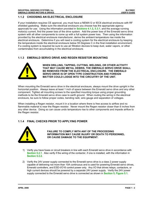
1.1.3 EMERALD SERVO DRIVE AND REGEN RESISTOR MOUNTING<br />
WHEN DRILLING, TAPPING, CUTTING, WELDING, OR OTHER ACTIVITY<br />
THAT MAY CAUSE METAL DEBRIS, THE EMERALD SERVO DRIVE SHALL<br />
BE REMOVED FROM THE ELECTRICAL ENCLOSURE. THE EMERALD<br />
SERVO DRIVE IS OF OPEN TYPE CONSTRUCTION AND FOREIGN<br />
MATTER COULD LODGE INTO THE CIRCUITRY OF THE UNIT.<br />
When mounting the <strong>Emerald</strong> servo drive in the electrical enclosure, always mount the drive upright in the<br />
horizontal position. Always leave at least 1 inch of space between the <strong>Emerald</strong> servo drive and any other<br />
component. Tighten all mounting screws to the specified mounting torque using proper grounding<br />
methods to tie the <strong>Emerald</strong> servo drive case to earth ground. When routing the wiring in the electrical<br />
enclosure, be sure to follow proper codes, bending radii, wire gauge and separation of voltages.<br />
When installing a Regen resistor, mount it in a location where there is free access to airflow and no<br />
flammable material is near the Regen resistor. Never mount the Regen resistor closer than 6 inches from<br />
any other device. Doing so can cause undo temperature rise to other components and impede airflow to<br />
the Regen resistor.<br />
1.1.4 FINAL CHECKS PRIOR TO APPLYING POWER<br />
FAILURE TO COMPLY WITH ANY OF THE PROCEEDING<br />
INFORMATION MAY CAUSE INJURY OR DEATH TO PERSONNEL<br />
OR CAUSE DAMAGE TO THE EQUIPMENT.<br />
1) Verify you have fuses or circuit breakers in line with each <strong>Emerald</strong> servo drive in accordance with<br />
Section 5.2.1. Also verify if the wiring of the contactor, if one is installed, with the information in<br />
Section 5.2.2.<br />
2) Verify the 24V power supply connected to the <strong>Emerald</strong> servo drive is a class 2 power supply<br />
capable of delivering not more than 10A continuous and is used for powering <strong>Emerald</strong> servo drives,<br />
<strong>Emerald</strong> controllers, and ESD-I/O16 control power only. Any I/O that drives relays, contactors, or<br />
high current devices should be powered by a separate 24V power supply. Verify the 24V power<br />
supply connected to the <strong>Emerald</strong> servo drive is connected as shown in Section 5, Figure 5.1.<br />
APRIL 2008 PAGE 1 - 2