Emerald Motors & Drive Manual - Industrial Indexing Systems
Emerald Motors & Drive Manual - Industrial Indexing Systems
Emerald Motors & Drive Manual - Industrial Indexing Systems

Create successful ePaper yourself
Turn your PDF publications into a flip-book with our unique Google optimized e-Paper software.
INDUSTRIAL INDEXING SYSTEMS, Inc.<br />
EMERALD SERIES MOTORS & DRIVES<br />
5.2.4 TRANSFORMERS (cont’d)<br />
IB-21B001<br />
USER’S GUIDE<br />
One transformer can supply multiple motor/driver packages. Simply add the rated mechanical output of<br />
the motor/driver packages together and use the above formulas. If one transformer is used to supply<br />
multiple drivers, be sure to protect each driver with the appropriate circuit breaker or fuse.<br />
IIS offers a full line of transformers for various line voltage and frequencies, enclosed and open frame<br />
types. Contact IIS Application Engineering Department for full details.<br />
5.2.5 WIRING PRACTICES AND GROUNDING<br />
All wiring must conform to accept standards such as NEMA and NEC codes. Signal and low voltage I/O<br />
wires must be physically separated from high voltage wires by at least 12 inches or separated by a<br />
suitable barrier such as steel conduit or wiring trough separator.<br />
The driver must be adequately grounded for proper operation and to provide personnel safety. The<br />
proper grounding technique is shown in Figure 5.1.<br />
5.3 DRIVER REGENERATION CAPACITIES<br />
The <strong>Emerald</strong> motor and driver have the ability to act as a brake for a rotating load. This condition<br />
typically occurs during the deceleration of the load or when the system is stopping a vertical load such as<br />
an elevator or lift. In both cases, the driver may have to absorb the mechanical and potential energy in<br />
the system. The driver must absorb the energy if the energy in the load exceeds to mechanical losses in<br />
the system.<br />
The driver has 2 ways to absorb the energy from the load.<br />
• Store the energy by charging the internal main DC bus capacitors (E C )<br />
• Dissipate the energy using a regeneration resistor (P R )<br />
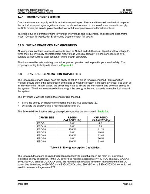
The <strong>Emerald</strong> driver internal energy absorption capacities are as shown in Table 5.4.<br />
DRIVER SIZE<br />
REGEN<br />
CAPACITY (P R )<br />
CHARGING<br />
CAPACITY (E C )<br />
ESD-5 0 W 4.0J<br />
ESD-10 0 W 5.4J<br />
ESD-20 120 W 11.2J<br />
ESD-25 0 W 19.8J<br />
ESD-40 120 W 22.4J<br />
ESD-50 0 W 26.5J<br />
ESD-60 300 W 33.6J<br />
Table 5.4 - Energy Absorption Capabilities<br />
The <strong>Emerald</strong> drivers are equipped with internal circuitry to detect a rise in the main DC power bus<br />
indicating energy absorption. If the DC power bus reaches approximately 410 VDC on a ESD-XX/AXX<br />
drive, 820 VDC on a ESD-XX/CXX drive, the regeneration circuit is turned on to prevent the main DC<br />
power bus from rising to 430 VDC on a ESD-XX/AXX drive, 860 VDC on a ESD-XX/CXX drive, which will<br />
result in an over voltage alarm F02.<br />
APRIL 2008 PAGE 5 - 6