Slides explaining Boundary Scan test principles - goJTAG
Slides explaining Boundary Scan test principles - goJTAG
Slides explaining Boundary Scan test principles - goJTAG

Create successful ePaper yourself
Turn your PDF publications into a flip-book with our unique Google optimized e-Paper software.
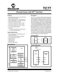
TAP Controller State Diagram<br />
DR Branch<br />
IR Branch<br />
The TAP state diagram<br />
has two main branches<br />
and two idle states.<br />
Shift IR and Shift DR<br />
states are used to insert<br />
instructions and <strong>test</strong><br />
data into the BS device.<br />
These are the most<br />
important states.<br />
The number of states is<br />
exactly 16 (to avoid<br />
some undefined states)<br />
TMS signal is used to<br />
move through the states<br />
43